EP0803722A2 - Dämpfungsprüfer in Schwenkung - Google Patents
Dämpfungsprüfer in Schwenkung Download PDFInfo
- Publication number
- EP0803722A2 EP0803722A2 EP97106371A EP97106371A EP0803722A2 EP 0803722 A2 EP0803722 A2 EP 0803722A2 EP 97106371 A EP97106371 A EP 97106371A EP 97106371 A EP97106371 A EP 97106371A EP 0803722 A2 EP0803722 A2 EP 0803722A2
- Authority
- EP
- European Patent Office
- Prior art keywords
- measured
- wheels
- vehicle
- roll
- measuring
- Prior art date
- Legal status (The legal status is an assumption and is not a legal conclusion. Google has not performed a legal analysis and makes no representation as to the accuracy of the status listed.)
- Withdrawn
Links
Images


Classifications
-
- G—PHYSICS
- G01—MEASURING; TESTING
- G01M—TESTING STATIC OR DYNAMIC BALANCE OF MACHINES OR STRUCTURES; TESTING OF STRUCTURES OR APPARATUS, NOT OTHERWISE PROVIDED FOR
- G01M17/00—Testing of vehicles
- G01M17/007—Wheeled or endless-tracked vehicles
- G01M17/04—Suspension or damping
- G01M17/045—Suspension or damping the vehicle wheels co-operating with rotatable rollers
Definitions
- This invention relates to a suspension rolling tester for measuring the movement of suspensions of a vehicle when the vehicle is rolled.
- a ratio of load movement of the right and left wheels is largely differentiated between the front and rear wheels owing to the difference of a spring constant in the suspensions of the coil springs of the front and rear wheels of the vehicle.
- the load movement ratio exerts an influence upon steering characteristics (under steering or over steering of the vehicle).
- an alignment characteristic of the wheels is also changed to vary the steering characteristic.
- the movement of the suspensions when the rolling occurs namely, the load movement amount and the alignment variation amount between the inner and outer wheels, i.e. the right and left wheels are respectively measured and these amounts are required to be always kept in a good condition (normal state) so as to permit the vehicle to travel safely.
- the vehicle to be measured is carried in or conveyed to a garage, then it is generally fixed by a fixing means, and a vertical movement is applied to the right and left wheels of the fixed vehicle by a roll input device composed of a driving means such as a hydraulic cylinder which is installed in a pit formed by digging the earth to substantially a deep length, thereby rolling the suspensions of the wheels, so as to realize a condition as if the vehicle were actually rolled.
- a driving means such as a hydraulic cylinder which is installed in a pit formed by digging the earth to substantially a deep length, thereby rolling the suspensions of the wheels, so as to realize a condition as if the vehicle were actually rolled.
- the movement of the suspensions has been thus detected based on the result of measurement.
- the roll input device since a rolling force is applied to the vehicle to be measured, the roll input device becomes normally very complex and very large. Accordingly, such measuring device costs high in a manufacturing cost, requires a large-sized pit formed by digging the earth to substantially the deep length, needs an embedding construction for embedding the pit, and also requires a large accommodating or installing space.
- the conventional device becomes very large scaled, which is suitable for a developing department of an automobile maker and a large garage but which is however not suitable for a small scaled garage.
- This invention has been made in view of such conventional problems, and it is an object of the invention to provide a suspension rolling tester, which is simple in structure and manufactured at low cost, and wherein a vehicle to be measured is merely conveyed to a tester, and one pair of front or rear wheels are to be measured (e.g., front wheels) in a state where the vehicle is not restricted (free state) and other wheels (e.g., rear wheels) are not measured, and an external force is applied to the wheels not to be measured by a simple device so as to roll the vehicle, so that the movement of the suspensions of the wheels to be measured is measured.
- a suspension rolling tester which is simple in structure and manufactured at low cost, and wherein a vehicle to be measured is merely conveyed to a tester, and one pair of front or rear wheels are to be measured (e.g., front wheels) in a state where the vehicle is not restricted (free state) and other wheels (e.g., rear wheels) are not measured, and an external force is applied to the wheels not to be measured
- a suspension rolling tester of this invention includes a roll input device and measuring devices, wherein the roll input device guides rear wheels or front wheels not to be measured of a vehicle to be measured in a non-restriction state, the measuring devices guides front wheels or rear wheels to be measured which are opposite to the wheels not to be measured, and wherein the roll input device applies a rolling force to the rear wheels or front wheels not to be measured, and the measuring devices detect suspension data of the wheels to be measured when the vehicle to be measured is rolled.
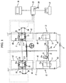
- Fig. 1 is a plan view showing an entire structure of a suspension rolling tester of this invention
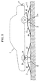
- Fig. 2 is a side view of Fig. 1
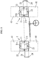
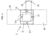
- Figs. 3 and 4 are views enlarging a part of Fig. 1
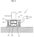
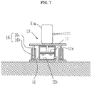
- Figs. 5 through 7 are respectively longitudinal cross sectional views of a roll input device of the suspension rolling tester and views enlarging the part of the roll input device
- Fig. 8 is a longitudinal cross sectional view showing a part of the measuring device of the suspension rolling tester.
- 1 a roll input device
- 2 and 2 are measuring devices.
- the roll input device 1 comprises, as illustrated principally in Fig. 5, a pair of simple structured elevating platforms 13 and 13, plate-shaped upper tables 11 and 11 on which the wheels not to be measured are placed, cylinder parts 12 and 12 of the elevating platforms 13 and 13 each having a piston part 12a for vertically moving the upper tables 11 and 11, an elevating platform control part 14 composed of a piping system including hoses or pipes for permitting fluid chambers 12b and 12b of the cylinder parts 12 and 12 of the elevating platforms 13 and 13 to communicate with each other, and a solenoid valve 14a and a throttle valve 14b which are provided on the elevating platform control part 14, if necessary, and a handy elevating means 15 composed of a jack (a garage jack, an air jack, a simple cylinder) which is installed under a bottom (side sill) of the vehicle C so as to apply a rolling force to the wheels not to be measured.
- a jack a garage jack, an air jack, a simple cylinder
- guide means 16 and 16 respectively composed of a guide pin 16a and a guide cylinder 16b for receiving the guide pin 16a between respective upper tables 11 and 11 and respective tables 13a and 13a of the platforms 13 and 13 so as to secure smooth elevation of the upper tables 11 and 11.
- a track level or an angle sensor as an angle detecting means 17, which is disposed at an arbitrary position, e.g., on a rear bumper of the vehicle C for detecting a rolling angle (normally about 2°) of the vehicle C when the vehicle is rolled.
- inclination boards 40 and 40 or inclination blocks may be provided in a direction where the vehicle C moves in or moves out from the garage.
- the jack as the elevating means 15 is installed in the garage and is appropriately positioned in a biased manner under one of link pivots provided on the bottom of the vehicle after the vehicle C is conveyed to the garage, so that the vehicle C is liable to incline as shown by broken lines in Fig. 5 when an elevating part 15a of the elevating means 15 is raised or lowered.
- the right rear wheel H RR presses the upper table 11 downward so that fluid in the fluid chamber 12b of the cylinder part 12 moves to the fluid chamber 12b of the cylinder part 12 of the opposite side by way of the piping system of the elevating platform control part 14 for pushing the piston part 12a of the cylinder part 12 of the opposite side.
- the upper table 11 of the opposite side connected to the piston part 12a is pushed up, thereby raising the left rear wheels H RL .
- the solenoid valve 14a and the throttle valve 14b of the elevating platform control part 14 are opened.
- the rolling of the vehicle by the garage jack is less frequently performed while the solenoid valve 14a is closed and the throttle valve 14b is throttled in a state where the throttle valve 14b is slightly opened (in an orifice state).
- the garage jack is removed under the vehicle so as to intermittently open or close the solenoid valve 14a so that the fluid is permitted to flow from the throttle valve 14b little by little to regulate the rolling angle to a prescribed value (normally about 2°).
- the rolling state of the vehicle C is realized. That is, the rolling state can be simply and quickly realized by merely operating the garage jack or operating the solenoid valve 14a and the throttle valve 14b.
- the rolling angle at this time can be read by the angle detector 17.
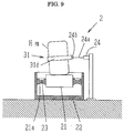
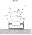
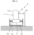
- the measuring devices 2 and 2 are disposed at positions corresponding to a pair of front wheels H FL and H FR of the vehicle C as is evident from Fig. 8, and they comprise placing tables 21 and 21 on which the pair of front wheels H FL and H FR are placed and frame bodies 22 and 22 for accommodating the placing tables 21 and 21 therein, and wheel load meters 23 and 23 which are installed at beam parts (bending parts) 21a for supporting the placing tables 21 and 21 and are composed of a load cell such as a strain gage for measuring the wheel load.
- a load cell such as a strain gage
- alignment variation measuring parts 24 and 24 composed of wired type displacement sensors (non-contact type distance sensors, for example, laser displacement sensors and supersonic wave sensors) outside the pair of front wheels H FL and H FR for measuring the variation of the alignment of the wheels to be measured.
- wired type displacement sensors non-contact type distance sensors, for example, laser displacement sensors and supersonic wave sensors
- the inclination boards 40 and 40 or inclination blocks may be provided in a direction where the vehicle C moves in or moves out from the garage.
- the measured data from the wheel load meters 23 and 23 and the alignment variation measuring parts 24 and 24 are respectively inputted into an arithmetic operation device 25 so that the arithmetic operation device 25 can perform various operations, and a result of operation can be displayed on a display 26 such as a CRT.
- the result of operation can be outputted by an output device 27 such as a printer, or it is stored in a storage medium 28 such as a floppy disk which is inserted into or out from a driving device attached to the arithmetic operation device 25.
- Data detected by an angle sensor as the angle detector 17 can be also directly inputted into the arithmetic operation device 25.
- the output data therefrom can be detected as the wheel load as it is.
- the alignment variation measuring parts 24 and 24 it is required to be devised to some extent.
- an attachment holder 31 for detecting the displacement of the wheel is attached to the wheel, and a wire 24a of the alignment variation measuring part 24 is brought into contact with the attachment holder 31.
- the attachment holder 31 comprises a metal member 31a having, e.g., a frame groove, a metal slide member 31b which is slidably accommodated in the frame groove, a lock part 31c for fixing the metal slide member 31b at an appropriate position, and clamping pieces 31d and 31d which are respectively fixed to the free end of the metal member 31a and the free end of the metal slide member 31b and are brought into contact with an outer periphery of the wheel.
- a magnet part 24b is provided on the tip end of the wire 24a so as to be magnetically attracted by the clamping pieces 31d and 31d.
- the wire 24a is caught by a hook which is provided on the metal member 31a or metal slide member 31b.
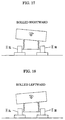
- an attachment plate 32 for measuring the displacement of the alignment which is excellent in reflective characteristic is provided on the side of the wheel to be measured as shown in Fig. 11 so that laser beam irradiated the wheel to be measured can be reflected in good condition.
- the supersonic wave sensor it is not necessary to provide the attachment plate 32 because the reflection of the supersonic waves from the wheel per se can be obtained in good condition.
- the height of the roll input device 1 in the longitudinal direction can be minimized because the rolling angle is about 2° at which the rolling force is applied to the vehicle, and a large elevating stroke is not required. Accordingly, the vehicle C can easily get on the upper tables 11 and 11 by the employment of the inclination boards 40 and 40. In the case of embedding the pit P in the floor of the garage, the floor or earth can be dug shallow, thereby saving the embedding cost.
- each measuring device 2 is more simplified so that the height thereof in the longitudinal direction can be minimized. Even in the case of embedding the measuring devices 2 and 2 in the pit of the garage, the pit P is enough to be shallow.
- the measurement of the movement of the suspensions at the rolling time namely, the measurement of the load movement amount and the alignment variation amount between the inner and outer wheels can be performed as follows.
- the vehicle C is first conveyed to the testing part, and the pair of front wheels H FL and H FR to be measured are placed on the measuring devices 2 and 2 while the pair of rear wheels H RL and H RR not to be measured are placed on the roll input device 1 as shown in Fig. 1 in a state where the vehicle C is not fixed to the testing part, namely in a non-restriction state (free state).
- the garage jack of the elevating means 15 of the roll input device 1 is operated or driven in the free state of the vehicle C so as to apply the rolling force to the wheels not to be measured as shown in the broken lines in Fig. 5, and thereafter the garage jack is removed.
- the right rear wheel H RR lowers but the left rear wheel H RL rises so that the rolling occurs easily at the rear side of the vehicle C.
- the height of the vehicle C is varied at the pair of rear wheels H RL and H RR respectively contacting the earth or the upper table, so as to realize a state of the cornering operation during the traveling of the vehicle C.
- the rolling is performed in a state where the vehicle C is not fixed but in a non-restriction state (free state) where it is merely conveyed to the garage, it dispenses with the fixing operation. Further, since there is not provided a fixing means, the vehicle C is neither damaged unnecessarily nor deformed at all.
- the wheel load of the wheels to be measured is measured by the wheel load meters 23 and 23 and the variation of alignment of the wheels is measured by the alignment variation measuring parts 24 and 24, and the resultant measured data is inputted into the arithmetic operation device 25 so that the arithmetic operation device 25 can perform a given arithmetic operation.
- the increment or decrement of the load applied to each wheel is calculated by measuring the load of wheels to be measured based on which a roll rigidity, a sharing ratio of the roll rigidity and a sharing ratio of the load movement are respectively calculated. It is possible to calculate a toe angle and a camber angle of the wheels to be measured, and also possible to calculate a roll steering ratio of each wheel based on the toe angle.
- a front roll rigidity K F of the pair of front wheels H FL and H FR can be calculated from the following expression (1).
- K F [+ ⁇ W - (- ⁇ W)] ⁇ (T F /2)/ ⁇ where + ⁇ W is an increment of the load of the right front wheel H FR , - ⁇ W is a decrement of the load of the left front wheel H FL , T F is a front tread, i.e. the distance between the pair or front wheels at the center thereof, ⁇ is a roll angle (e.g., 2°).
- a rear roll rigidity K R of the pair of rear wheels H RL and H RR can be calculated by the following expression (2).
- K R [+ ⁇ W' - (- ⁇ W')] ⁇ (T R /2)/ ⁇ where + ⁇ W' is an increment of the load of the right rear wheel H RR , - ⁇ W' is a decrement of the load of the left rear wheel H RL , T R is a rear tread, i.e. the distance between the pair or rear wheels at the center thereof ⁇ is a roll angle (e.g., 2°).
- the front roll rigidity sharing ratio is calculated by the expression of K F /K F + K R .
- the rear roll rigidity sharing ratio is calculated as the expression of K R /K F + K R .
- the sharing ratio of the front roll rigidity relative to the rear roll rigidity becomes substantially the same as a load movement sharing ratio between the front and rear wheels. Accordingly, when the load movement sharing ratio is calculated, it can correspond to the sharing ratio of the front roll rigidity relative to the rear roll rigidity (K F : K R ).
- the front roll rigidity sharing ratio and the rear roll rigidity sharing ratio are possible to correspond to the front load movement sharing ratio expressed by the front load movement amount/total load movement amount, and to the rear load movement rigidity sharing ratio expressed by the rear load movement amount/total load movement amount.
- the roll steering angle can be calculated by the variation of the toe angle when the vehicle is rolled.
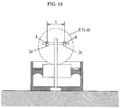
- alignment variation measuring parts 24 and 24 namely, two wired type displacement sensors 24 and 24 are positioned to confront each other at two points (points A and B) in the horizontal direction of the wheels to be measured as shown in Figs. 1 and 13 and the wires 24a and 24a of the alignment variation measuring parts 24 and 24 are brought into contact with the attachment holders 31 and 31 as shown in Fig. 9.
- the toe angle ⁇ T is calculated by the following expression (3).
- ⁇ T tan -1 [(a-b)/L] where a is a variation value at the point A, b is a variation value at the point B, L is a distance between two points (points A and B). If the variation of the toe angle is very small, it can be approximately calculated by the expression of ⁇ T ⁇ (a-b)/L .
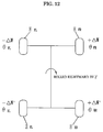
- an average roll steering angle ⁇ FR of the right front wheel H FR is expressed as an average of the variation inclination of the values r 1 and r 2 , namely, [r 1 - (-r 2 )]/2 .
- the roll steering ratio of the right front wheel H FR is calculated as follows by measuring the roll steering angle ⁇ FR , namely, ( ⁇ FR /2°) ⁇ 100 (%value) .
- the roll steering angles ⁇ FL, ⁇ RL, ⁇ RR of the other wheels H FL, H RL, H RR and the roll steering ratio are also calculated.
- the roll steering ratio (%value) of the left rear wheel H RL is calculated by obtaining the average (average roll steering angle ⁇ RL ) of the variation inclination of the values r 1 and r 2 when the rear wheels are rolled rightward and leftward, then the average roll steering angle ⁇ RL is divided by the roll angle (2°), and multiplying the resultant divided value by 100.
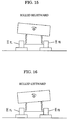
- Two wired type alignment variation sensors 24 and 24 are positioned to confront each other at two points in the vertical direction of the wheels to be measured, and the wires 24a and 24a are permitted to bring into contact with the attachment holder 31, a camber angle at the rolling time can be measured.
- the two wired type alignment variation sensors 24 and 24 for measuring the toe angle shown in Fig. 13 may be structured as a rotary mechanism which can be converted into horizontally and vertically, if need be, for measuring both the toe angle and the camber angle.
Landscapes
- Physics & Mathematics (AREA)
- General Physics & Mathematics (AREA)
- Body Structure For Vehicles (AREA)
- Vehicle Body Suspensions (AREA)
- Length Measuring Devices With Unspecified Measuring Means (AREA)
Applications Claiming Priority (2)
| Application Number | Priority Date | Filing Date | Title |
|---|---|---|---|
| JP130741/96 | 1996-04-26 | ||
| JP8130741A JP3053570B2 (ja) | 1996-04-26 | 1996-04-26 | ローリングサスペンションテスタ |
Publications (2)
| Publication Number | Publication Date |
|---|---|
| EP0803722A2 true EP0803722A2 (de) | 1997-10-29 |
| EP0803722A3 EP0803722A3 (de) | 1998-04-01 |
Family
ID=15041527
Family Applications (1)
| Application Number | Title | Priority Date | Filing Date |
|---|---|---|---|
| EP97106371A Withdrawn EP0803722A3 (de) | 1996-04-26 | 1997-04-17 | Dämpfungsprüfer in Schwenkung |
Country Status (3)
| Country | Link |
|---|---|
| US (1) | US5864053A (de) |
| EP (1) | EP0803722A3 (de) |
| JP (1) | JP3053570B2 (de) |
Cited By (1)
| Publication number | Priority date | Publication date | Assignee | Title |
|---|---|---|---|---|
| EP1184641A1 (de) * | 2000-09-02 | 2002-03-06 | Beissbarth GmbH | Verfahren und Einrichtung zur Fahrwerkvermessung |
Families Citing this family (8)
| Publication number | Priority date | Publication date | Assignee | Title |
|---|---|---|---|---|
| JP2001033234A (ja) * | 1999-07-16 | 2001-02-09 | Bridgestone Corp | タイヤ位置検出装置及びホイールアライメント調整装置 |
| EP1199540A1 (de) * | 2000-10-18 | 2002-04-24 | Willy Lambrecht | Radmanipulator |
| US7140242B1 (en) * | 2004-07-22 | 2006-11-28 | Akron Special Machinery | Lateral load tire testing system |
| ES2388188T3 (es) * | 2008-01-09 | 2012-10-10 | Siemens Aktiengesellschaft | Centrado de vehículo en el estado de ajuste del mecanismo de traslación y procedimiento correspondiente |
| JP5385704B2 (ja) * | 2009-07-01 | 2014-01-08 | 株式会社ブリヂストン | 車両輪荷重調整装置 |
| CN102401744A (zh) * | 2010-09-16 | 2012-04-04 | 软控股份有限公司 | 轮胎耐久性倾角检测装置及其方法 |
| WO2016044590A1 (en) * | 2014-09-17 | 2016-03-24 | Power Stream Industries, Inc. | Dynamic test pad and testing platform for motor vehicles |
| CN114705459B (zh) * | 2022-06-01 | 2022-09-09 | 山东美晨工业集团有限公司 | 一种底盘悬架振动检测装置 |
Family Cites Families (14)
| Publication number | Priority date | Publication date | Assignee | Title |
|---|---|---|---|---|
| US3689161A (en) * | 1970-12-10 | 1972-09-05 | Fmc Corp | Optical unit for wheel aligner |
| EP0185790B1 (de) * | 1984-12-24 | 1989-03-15 | Carl Schenck Ag | Verfahren zum Übertragen von Kräften und/oder Momenten sowie Vorrichtung hierzu |
| US4679327A (en) * | 1986-07-07 | 1987-07-14 | Chrysler Motors Corporation | Front wheel drive vehicle, automatic toe set alignment system, therefor |
| US5040303A (en) * | 1988-03-29 | 1991-08-20 | Arthur Koerner | Toe adjustment method and apparatus |
| JP2565384B2 (ja) * | 1988-09-30 | 1996-12-18 | 富士重工業株式会社 | 自動車用アクティブサスペンションの制御装置 |
| JPH02182581A (ja) * | 1989-01-10 | 1990-07-17 | Mazda Motor Corp | サスペンションとステアリングの総合制御装置 |
| US5111585A (en) * | 1989-11-21 | 1992-05-12 | Iyasaka Seiki Co., Ltd. | Method and apparatus for measuring and adjusting the wheel alignment of automotive vehicles |
| NL9001989A (nl) * | 1990-09-10 | 1992-04-01 | Analogic Eng Bv | Inrichting voor het beproeven van de wielophanging van een voertuig. |
| JP3280392B2 (ja) * | 1991-04-01 | 2002-05-13 | アイシン・エィ・ダブリュ株式会社 | 電動車両の駆動力制御装置 |
| US5267466A (en) * | 1991-09-26 | 1993-12-07 | Ford Motor Co. | Apparatus and method for calibrating a suspension control module |
| JP3196494B2 (ja) * | 1994-02-25 | 2001-08-06 | 日産自動車株式会社 | サスペンション制御装置 |
| JP3066391B2 (ja) * | 1994-07-27 | 2000-07-17 | 日産自動車株式会社 | コンプライアンステスター |
| US5574226A (en) * | 1995-04-06 | 1996-11-12 | Ford Motor Company | Transportable environmental test facility |
| US5723782A (en) * | 1996-11-29 | 1998-03-03 | Bolles, Jr.; Robert C. | Method of land vehicle suspension evaluation and design through roll angle analysis |
-
1996
- 1996-04-26 JP JP8130741A patent/JP3053570B2/ja not_active Expired - Fee Related
-
1997
- 1997-04-17 EP EP97106371A patent/EP0803722A3/de not_active Withdrawn
- 1997-04-18 US US08/845,080 patent/US5864053A/en not_active Expired - Fee Related
Cited By (1)
| Publication number | Priority date | Publication date | Assignee | Title |
|---|---|---|---|---|
| EP1184641A1 (de) * | 2000-09-02 | 2002-03-06 | Beissbarth GmbH | Verfahren und Einrichtung zur Fahrwerkvermessung |
Also Published As
| Publication number | Publication date |
|---|---|
| EP0803722A3 (de) | 1998-04-01 |
| JPH09292313A (ja) | 1997-11-11 |
| JP3053570B2 (ja) | 2000-06-19 |
| US5864053A (en) | 1999-01-26 |
Similar Documents
| Publication | Publication Date | Title |
|---|---|---|
| EP0803722A2 (de) | Dämpfungsprüfer in Schwenkung | |
| US7380462B2 (en) | Apparatus and method for measuring supporting force of large diameter ferroconcrete piles | |
| CN105136488B (zh) | 一种用于磁悬浮列车转向架检测的试验装置及其检测方法 | |
| CN108507659B (zh) | 用于校准动态称重传感器的装置和方法 | |
| US7278215B2 (en) | Method and device for measuring wheel alignment of automobile | |
| EP3228976B1 (de) | Vorrichtung und verfahren zum bewerten von fahrzeugradausrichtung | |
| EP0977010B1 (de) | Justierungsverfahren für Kraftfahrzeugradausrichtung | |
| CN105823598A (zh) | 一种客车质心位置测量装置及测量计算方法 | |
| US6257371B1 (en) | Lifting platform for double-tracked vehicles | |
| CN108332984A (zh) | 机具-土壤作用力土槽试验检测装置及其方法 | |
| EP3978889A1 (de) | Dynamische lastschwerpunkterkennung | |
| US11473962B2 (en) | Method and device for detecting the weight of a load moving on scales | |
| CN101103245B (zh) | 车轮前端角度测定装置以及测定方法 | |
| AU751516B2 (en) | Vehicle weighing system for dynamometer | |
| CZ67999A3 (cs) | Zkušební zařízení vozidel | |
| US6729032B2 (en) | Chassis measuring apparatus and method of measuring a chassis | |
| US3456489A (en) | Shock absorber tester | |
| US4036315A (en) | Weighing system | |
| JP2993312B2 (ja) | 車両のロール特性試験装置 | |
| JP3424116B2 (ja) | 前後輪測定用ホイルアライメント測定装置 | |
| JP2004012195A (ja) | 自動車のホイルアライメント測定方法及びその装置 | |
| CN205691344U (zh) | 抬轿式气囊举升制动试验台 | |
| US5753865A (en) | Load measurement | |
| JP2024545000A (ja) | 車両試験スタンド上に車両を位置決めするための方法 | |
| JP2801244B2 (ja) | 車輌サスペンション特性測定方法 |
Legal Events
| Date | Code | Title | Description |
|---|---|---|---|
| PUAI | Public reference made under article 153(3) epc to a published international application that has entered the european phase |
Free format text: ORIGINAL CODE: 0009012 |
|
| AK | Designated contracting states |
Kind code of ref document: A2 Designated state(s): DE FR |
|
| PUAL | Search report despatched |
Free format text: ORIGINAL CODE: 0009013 |
|
| AK | Designated contracting states |
Kind code of ref document: A3 Designated state(s): DE FR |
|
| 17P | Request for examination filed |
Effective date: 19980902 |
|
| 17Q | First examination report despatched |
Effective date: 20020508 |
|
| STAA | Information on the status of an ep patent application or granted ep patent |
Free format text: STATUS: THE APPLICATION IS DEEMED TO BE WITHDRAWN |
|
| 18D | Application deemed to be withdrawn |
Effective date: 20020919 |