EP0803701A2 - Mécanisme de déploiement multiaxial à mouvement synchronisé contrÔlé - Google Patents
Mécanisme de déploiement multiaxial à mouvement synchronisé contrÔlé Download PDFInfo
- Publication number
- EP0803701A2 EP0803701A2 EP97250096A EP97250096A EP0803701A2 EP 0803701 A2 EP0803701 A2 EP 0803701A2 EP 97250096 A EP97250096 A EP 97250096A EP 97250096 A EP97250096 A EP 97250096A EP 0803701 A2 EP0803701 A2 EP 0803701A2
- Authority
- EP
- European Patent Office
- Prior art keywords
- axis
- rotation
- wing
- elevation
- frame
- Prior art date
- Legal status (The legal status is an assumption and is not a legal conclusion. Google has not performed a legal analysis and makes no representation as to the accuracy of the status listed.)
- Granted
Links
- 230000007246 mechanism Effects 0.000 title claims abstract description 73
- 230000001360 synchronised effect Effects 0.000 title abstract description 4
- 239000011888 foil Substances 0.000 claims abstract description 93
- 239000012530 fluid Substances 0.000 claims description 36
- 230000007704 transition Effects 0.000 abstract description 2
- 239000007789 gas Substances 0.000 description 5
- 238000000926 separation method Methods 0.000 description 4
- 230000035939 shock Effects 0.000 description 4
- 239000006096 absorbing agent Substances 0.000 description 3
- 238000012986 modification Methods 0.000 description 3
- 230000004048 modification Effects 0.000 description 3
- 238000007789 sealing Methods 0.000 description 3
- 102000003979 Mineralocorticoid Receptors Human genes 0.000 description 2
- 108090000375 Mineralocorticoid Receptors Proteins 0.000 description 2
- 230000008901 benefit Effects 0.000 description 2
- 230000007423 decrease Effects 0.000 description 2
- 238000013461 design Methods 0.000 description 2
- 230000009977 dual effect Effects 0.000 description 2
- 229910000831 Steel Inorganic materials 0.000 description 1
- 230000009471 action Effects 0.000 description 1
- 230000004913 activation Effects 0.000 description 1
- XAGFODPZIPBFFR-UHFFFAOYSA-N aluminium Chemical compound [Al] XAGFODPZIPBFFR-UHFFFAOYSA-N 0.000 description 1
- 229910052782 aluminium Inorganic materials 0.000 description 1
- 238000013459 approach Methods 0.000 description 1
- 230000009172 bursting Effects 0.000 description 1
- 238000005266 casting Methods 0.000 description 1
- 238000010276 construction Methods 0.000 description 1
- 230000008878 coupling Effects 0.000 description 1
- 238000010168 coupling process Methods 0.000 description 1
- 238000005859 coupling reaction Methods 0.000 description 1
- 238000013016 damping Methods 0.000 description 1
- 230000003247 decreasing effect Effects 0.000 description 1
- 238000000034 method Methods 0.000 description 1
- 230000000284 resting effect Effects 0.000 description 1
- 239000010959 steel Substances 0.000 description 1
- 238000012546 transfer Methods 0.000 description 1
Images


Classifications
-
- F—MECHANICAL ENGINEERING; LIGHTING; HEATING; WEAPONS; BLASTING
- F42—AMMUNITION; BLASTING
- F42B—EXPLOSIVE CHARGES, e.g. FOR BLASTING, FIREWORKS, AMMUNITION
- F42B10/00—Means for influencing, e.g. improving, the aerodynamic properties of projectiles or missiles; Arrangements on projectiles or missiles for stabilising, steering, range-reducing, range-increasing or fall-retarding
- F42B10/02—Stabilising arrangements
- F42B10/14—Stabilising arrangements using fins spread or deployed after launch, e.g. after leaving the barrel
Definitions
- This invention relates to an air foil deployment system for use on a missile, rocket or the like.
- a mechanism for deploying an air foil.
- the mechanism includes a frame and a pivot pin pivotally mounted on the frame for pivotal motion between a first position and a second position about a first axis.
- An air foil is mounted to the pivot pin. The air flow over the air foil can be used to move the air foil and pivot pin from the first position to the second position.
- a pressurized fluid, pyrotechnic or drogue chute can be used for pivoting the air foil and pin between the first and second positions.
- a cam is mounted on the frame which causes elevation of the air foil about a second axis perpendicular to the first axis as the pivot pin moves from the first position to the second position.
- the pivot pin is secured to a rotation gear which meshes with a rack shaft.
- the mechanism can also include a sliding gear rack engaging the cam.
- the sliding gear rack has teeth meshed with teeth on the air foil.
- the mechanism has a lock to lock the air foil in the elevated and rotated position.
- a stop device can be provided to limit the motion of the air foil into the elevated and rotated position.
- the mechanism can have a second air foil which is deployed to the rotated and elevated position simultaneously with the first air foil.
- the mechanism has an unfolding motion rate limiting orifice through which hydraulic fluid is forced.
- This orifice is adjustable to provide alternate air foil deployment time histories.
- a mechanism for deploying an air foil.
- the mechanism includes a frame and an elevation plate mounted on the frame for pivotal motion about a first axis.
- a T-joint is mounted to the frame for pivotal motion about a second axis.
- a wing assembly is mounted to the T-joint for pivotal motion about a third axis between a storage position and an elevated position. Pivotal motion of the T-joint about the second axis causes pivotal motion of the elevation plate about the first axis and of the wing assembly about the third axis.
- the wing assembly is formed by a wing mounted on a wing root. Further, the first and second axes are parallel and the third axis is perpendicular thereto.
- the wing root has a series of gear teeth thereon and the elevation plate has a series of gear teeth thereon, the gear teeth on the wing root and elevation plate in meshing engagement.
- a second mechanism is provided, the elevation plate of each mechanism having a series of beveled gear teeth around the peripheries thereof.
- a cross shaft having beveled teeth engaging the beveled teeth on the elevation plates insure joint motion of the elevation plates.
- a hydraulic damper is in operable engagement with the cross shaft to control the speed of motion of the elevation plates.
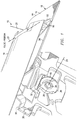
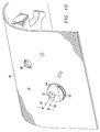
- a mechanism 10 is illustrated which is capable of deploying simultaneously a pair of air foils 12 and 14 on the exterior surface 16 of a bridge structure 18.
- the bridge structure can be a portion of the frame or body of a rocket or missile. More specifically, the mechanism can be applied to the LOCAAS/LORISK air frame, although the general principles of this mechanism could be tailored to suit many different applications.
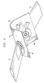
- the mechanism 10 allows pivotal motion of the air foils about rotation axes 20 while simultaneously pivoting the air foils about elevation axes 22 perpendicular to rotation axes 20 when moving between the folded configuration, seen in FIGURE 1, and the deployed configuration, shown in FIGURE 2, at an adjustably controlled rate.
- the bridge structure 18 can be seen to be formed in a symmetrical manner about its center line 24 to define first portion 56 and second portion 58.
- Each portion of the bridge structure includes a rack boss defining facing passages 26 and 28 for receiving the ends of a rack shaft 30.
- An aperture 32 through each portion of the bridge structure 18 receives a rotation axle 34 (best seen in FIGURE 7).
- a rotation gear 36 is secured to the inner end of the rotation axle 34 for rotation therewith by a snap ring 38.
- the teeth 40 of the rotation gear 36 are meshed with teeth 42 of the rack shaft 30.
- Each portion of the bridge structure 18 also has a threaded boss 44 which receives a bump stop 46.
- a lock boss defines a passage 48 which receives a rotation lock 50 that is urged toward the rotation gear 36 by a spring 52 (see FIGURE 3) in passage 48 acting on the lock 50.
- a passage 54 interconnects the passage 28 formed on the first portion 56 of the bridge structure 18 and passage 26 on the second portion 58 of the bridge structure 18. Hydraulic seals are provided at each end of the rack shafts 30 to seal against the surfaces of passages 26 and 28 to provide a hydraulic seal.
- the passage 26 on the first portion 56 connects to a pocket 66 which opens through the exterior surface 16 of the bridge structure 18.
- a hydraulic damper 68 which will be described in detail hereinafter, is mounted in the pocket 66 to control the movement of the rack shafts 30.
- the passage 26 in second portion 58, passage 54 and passage 28 on first portion 56 are completely filled with a hydraulic fluid.
- the fluid can be entered into the passages through a hydraulic fill port 60. It is important to bleed all air and other gases out of the passages so that fluid completely occupies the volume in the passages.
- a hydraulic volume adjust screw 61 in the fill port 60 allows the volume in the passages to be varied slightly by screwing the adjustment screw in or out. This permits an adjustment of the angle of the air foils to insure that the air foils are not skewed when in the folded or open configurations. It is desired to have the air foils oriented in the open position within 1 ⁇ 4° of angle relative each other.
- the passage 26 in the first portion 56 is completely filled with hydraulic fluid.
- any movement of one of the air foils is immediately transmitted through the hydraulic fluid to influence the other air foil. Further, movements of the air foils in the direction of deployment will pressurize the hydraulic fluid in the passage 26 in the first portion 56, exerting a force on the hydraulic damper 68, which causes a pressure diaphragm to burst and thereafter controlling the rate of discharge of the hydraulic fluid and thus controlling the rate of deployment of the air foils.
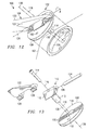
- each rotation axle 34 can be seen to end in a cylinder 80 with a bore 82 therethrough which extends along the elevation axis 22.
- the air foils 12 and 14 each have a pair of extensions 84 which fit around the ends of the cylinder 80 and have bores 86 formed therein.
- a shaft 88 passes through bores 82 and 86 to pivotally secure the air foils 12 and 14 to the rotation axles 34 for pivotal motion about the elevation axis 22.
- each of the extensions 84 have a series of elevation gear teeth 90 thereon.
- a sliding gear rack 92 is mounted on the exterior surface 16 about each aperture 32.
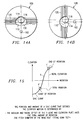
- the sliding gear rack 92 engages an eccentric boss 94 formed on the exterior surface 16 about each of the apertures 32, as seen in FIGURE 11.
- the exposed surface of the sliding gear rack 92 is formed of elevation gear teeth 96 which mesh with teeth 90 on the air foil.
- the sliding gear rack 92 is capable of pivotal motion relative the rotation axis 20 but, because of the eccentricity of the boss 94, the center axis of the sliding gear rack 92 is offset from the rotational axis 20.
- the eccentricity of boss 94 can be achieved by using a cylindrical boss 94 with its axis 99 offset from axis 20 as shown.
- a pressurized fluid or gas could be provided in passage 28 of portion 58 to drive the air foils to the deployed position.
- a pressurized fluid or gas could be provided in passage 28 of portion 58 to drive the air foils to the deployed position.
- an air or other gas pressure cylinder at perhaps 3,000 psi, can be used to pressurize the hydraulic fluid and deploy the air foils.
- a pyrotectic squib can be used to pressurize the hydraulic fluid.
- the rotation gears 36 are splined to the rotation axles 34 for joint rotation. As the pivotal motion is initiated about rotation axes 20, the sliding gear racks 92 also pivot through engagement with the air foils and begin to rotate on surface 16 around eccentric boss 94. The rotation is about axis 99. A clearance cut 93 may be necessary in boss 94 to pass teeth 90 of the air foils as the air foil and axle 34 pivot about axis 20.
- the structure is designed so that when the rotation gears 36 are stopped by bump stops 46, the air foils have been fully deployed both by movement about the rotation axis 20 and about the elevation axis 22.
- the deployed position can be adjusted slightly by threading bump stops 46 into or out of the threaded bosses 44. In the deployed position, the rotation locks 50 are urged into lock notches 70 on the rotation gears 36 to hold the air foils in the deployed position.
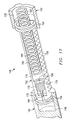
- the hydraulic damper 68 controls the deploying rate of the mechanism 10.
- An orifice housing 100 is fit within the pocket 66 and sealed thereto by an O-ring 102.
- the housing defines a small orifice to bleed hydraulic fluid from passage 26 in portion 56 to exterior the mechanism 10.
- An orifice rate adjustment screw 105 is screwed into housing 100.
- the orifice rate adjustment screw 105 has a tapered end 107 which extends into the orifice in the housing 100.
- the screw 105 can be threaded in or out of the housing to vary the area of the annulus formed between the tapered end 107 and the walls of the orifice in the housing.
- a burst diaphragm 106 is sealed over the orifice with an O-ring 108.
- a washer 110 provides the sealing pressure against the burst diaphragm 106 when snap ring 112 engages a retaining groove in the pocket 66, trapping the damper and compressing the O-ring 108 for sealing.
- the hydraulic pressure rapidly increases in the passage 26, bursting the diaphragm 106 and allowing the hydraulic fluid to escape at a controlled rate through the orifice, thus providing deployment of the air foils at a controlled rate.
- the rate of hydraulic fluid discharge, and therefore the rate of deployment of the air foils can be adjusted by threading the screw 105 further into the orifice housing 100 to decrease the area of the annulus between the orifice in the housing and the tapered end 107, thereby slowing the flow rate of fluid through the annulus and the rate of deployment, or backing the screw 105 slightly out of the housing 100 to enlarge the annulus between the orifice in the housing 100 and the tapered end 107 to increase the discharge rate of the hydraulic fluid, lessening the time of deployment of the air foils.
- a deployment rate of about 0.5 seconds is desired.
- the hydraulic damper is mounted through the exterior surface 16 of the bridge structure 18. This provides easy replacement of the burst diaphragm should the system be accidentally discharged.
- a shock absorber system could be used as a substitute.
- the shock absorber system would delay the deployment of the air foils at a rate determined by the shock absorber.
- the mechanism 10 provides for the facilitation of maximum load out of submunitions in delivery vehicles such as TACMs or MLRs.
- a minimum intrusive volume, two axis fold mechanism as disclosed allows aerodynamic surfaces or other devices, which normally extend perpendicular to the body length, to be folded along the submunition body length.
- the general principles of the mechanism disclosed herein could be tailored to suit many other different applications as well.
- the entire mechanism mounts as a modular unit. This allows assembly and adjustment of the wing anhedral and incidence angle to be performed prior to attachment to the main structure, as well as providing additional access to the interior of the vehicle for other assembly tasks.
- the air foils are folded forward along the fuselage of a vehicle, aerodynamic forces can provide the energy to open the air foils.
- the passage 28 on portion 58 need not be provided with a high pressure gas or fluid to activate the air foils.
- the mechanism is equally adaptable to the air foils being folded rearward along the fuselage by providing a suitable energy source to apply to the air foils to deploy the air foils against aerodynamic loads as discussed previously.
- the mechanism will function for a large range of rotation and elevation fold angles, allowing tailoring of the mechanism to many different applications.
- the bridge structure 18 can be a one-piece casting, including the bosses 94, the bosses necessary to form the hydraulic passages 26, 28, 54 and 60, the bosses for containing the rotation locks 50, the bump stops 46 and for general structural stiffening. Jig boring of the part is not required. A simple drill fixture will allow all hydraulic passages and axle or slide bores to be machined.
- the bridge structure is designed to fit both the glider and powered submunition LOCAAS vehicles with no modifications and provides a portion of the upper fuselage skin.
- the coupling through passages 54 as shown can be reversed side for side, or even used as a dual link system, if desired.
- each of the passages can be closed off with short press-in plugs or removable plugs, if desired.
- the gear racks For an aft deploying system (i.e., wings folded forward), the gear racks would move forward.
- a forward deploying system i.e., wings folded aft
- the gear racks would move aft.
- One option for an energy supply to open the air foils against aerodynamic loads on an aft folded system would be, as previously noted, to allow a gas generator squib to pressurize the forward end of a rack shaft, transferring the opening energy through the hydraulic link to open the other rack.
- the snap ring 38 securing the rotation gear 36 to the rotation axle 34 can be replaced by bolting the gear to the rotation axle.
- the physical distance between the sliding gear rack 92 axis 99 and the rotation axis 20 is determined by the desired ratio of air foil rotation to air foil elevation angles, and by the pitch diameter of the air foil gear teeth.
- rotation angle equals 90°
- elevation angle equals 49°
- air foil gear pitch diameter is 0.625 inch
- the sliding gear rack versus rotation axis separation must be 0.267 inch.
- Elevation angle (total fold angle) (sin[rotation angle])
- This particular arrangement illustrated allows the wing elevation motion to come up to a very soft stop, thus requiring damping in the rotation axis direction only.
- any number of air foils can be deployed by connecting the air foils through a hydraulic fluid connection as described previously.
- four air foils can be deployed simultaneously, if desired, with hydraulic circuits 26, 54, 28 connected in series to four air foils to deploy the air foils in a controlled synchronized manner.
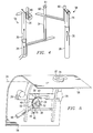
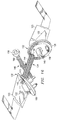
- the mechanism includes a pair of wing deployment apparatus 132, each having an air foil or wing 104.
- the mechanism 100 is mounted on bridge structure 102 which can be a portion of the frame or body of a rocket or missile also.
- the mechanism 100 deploys wings 104 simultaneously from a folded configuration to the deployed configuration at a controlled rate.
- a circular pocket 106 On each side of the center line of the bridge structure 102 is formed a circular pocket 106.
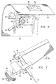
- An elevation plate 108 is received in the pocket such that it is confined by the walls of the pocket but can pivot about axis 130 shown in FIGURES 14A and 14B in the pocket.
- the elevation plate 108 has a shaped aperture 110 which receives a portion 113 of a T-joint fitting 112.
- a securing bolt 114 is inserted into the top of the T-portion 115 of the T-joint fitting with the head of the bolt resting against a flange within the fitting.
- the securing bolt is then threaded into the bridge structure 102 to secure the T-joint fitting and elevation plate 108 within the pocket 106.
- the T-joint fitting 112 is permitted to pivot about a rotation axis 116 coinciding with the center line of the securing bolt 114 while the elevation plate pivots about axis 130 at the center of pocket 106.
- the front surface 118 of the elevation plate 108 is formed with a series of gear teeth 120.
- a wing root 122 is mounted to the T-joint fitting 112 At T-portion 115 by an axle pin 124 which permits the wing root 122 to pivot about an elevation axis 126 relative the T-joint fitting 112.
- the wing root is formed with a series of gear teeth 128 which mesh with the gear teeth 120 on the elevation plate 108.
- the wing 123 itself is bolted or otherwise secured to the wing root to form the complete wing assembly or air foil 104.
- the elevation plate 108 and T-joint fitting 112 effectively slide relative each other so that the gear teeth 120 on the elevation plate 108 engaging the gear teeth 128 on the wing root 122 cause the wing root to move between the folded positipn F and the elevated position E.
- the shaped aperture 110 must be sufficiently large to allow the movement required between the elevation plate 108 and the T-joint fitting 112. It is illustrated as a kidney-shaped configuration in FIGURES 14a and 14b, making the mechanism bi-directional, allowing the wing to be elevated in either direction from the folded position. However, if only a single direction is necessary, the aperture 110 can be suitably modified. Further, the aperture 110 can clearly be simply a large enough circle to accommodate the necessary range of motion, if desired.
- FIGURE 15 illustrates a graph of the deployment of the wing from the folded position F to the deployed or elevated position E.
- the deployment follows a portion of a sine curve S which can be defined by the angular and radial offset of the T-joint axis of rotation 116 and the elevation plate axis of rotation 130, the total amount of rotation and the pitch diameter of the gear teeth on the wing root and T-joint fitting.
- a pair of wing deployment apparatus 132 can be mounted on the bridge structure 102 and operated simultaneously through the use of a cross shaft 134.
- the cross shaft 134 is mounted within the bridge structure 102 for rotational motion about its elongate axis.
- the back side 138 of each elevation plate 108 is provided with beveled gear teeth 140.
- the ends of the cross shaft 134 are similarly formed with beveled gear teeth 142, which mate with teeth 140.
- the cross shaft 134 can also be provided with spur teeth 144 to engage a hydraulic damper 146 to control the speed of deployment of the wings.
- a portion of the hydraulic damper 146 is formed by the bridge structure 102 itself defining a first fluid chamber 148 and a second fluid chamber 150 separated by an open passage facing the cross shaft 134.
- a damper piston 152 is sealed at its ends within the first and second fluid'chambers 148 and 150 by pairs of sealing rings 154.
- the middle portion of the damper piston 152 is provided with rack gear teeth 156 which mesh with the spur gear teeth on the cross shaft 134.
- a plug 158 which seals the fluid chamber but allows fluid to be added when necessary.
- the first fluid chamber 148 preferably is a blind boring, although a plug can be mounted in the end thereof, if desired.
- a spring 160 is positioned within the second fluid chamber 150 between the plug 158 and the damper piston 152 to either assist or retard wing deployment, depending on the particular direction of wing deployment rotation selected.
- a passage 164 is formed through the damper piston 152 to connect the first and second fluid chambers 148 and 150.
- the passage 164 is formed with different diameters.
- a bleed passage 166 provides a small diameter aperture to permit control of the flow rate of fluid from one fluid chamber to the other.
- a larger diameter intermediate passage 168 has a threaded wall to receive a threaded flow rate adjuster 170.
- the flow rate adjuster has a pin 172 at the end thereof which is extended into the bleed passage 166.
- Either the bleed passage 166, or pin 172, or both, are tapered so that screwing the flow rate adjuster 170 so that pin 172 moves either further into the bleed passage 166 or retracts out of the bleed passage varies the effective orifice size for flow of fluid between the fluid chambers 148 and 150, thus providing a control for the speed of deployment of the wings.
- a spring passage 174 is of larger diameter, containing a portion of the spring 160 and defining an annular spring surface 176 against which the end of the spring within the piston rests. The surface 176 is formed in the transition between spring passage 174 and intermediate passage 168.
- the pocket 106 within the bridge structure 102 can mount a locking pin 178.
- the locking pin is urged outwardly by a spring 180.
- the locking pin 178 will be forced into a locking pin hole 182 in the elevation plate 108 to lock the elevation plate 108 and wing in the deployed position.
- the pin 178 can be pushed out of hole 182 by a suitable tool from the outside surface of the elevation plate 108 to allow the wing to be moved back to the folded position.
- locking pins 178 can be used in each wing deployment apparatus, if desired.
- a single locking pin in one apparatus can be effective to lock both apparatus in the deployed position.
- both locking pins must be retracted simultaneously to permit the apparatus to be returned to the folded position.
- the wing root 122 can be made of 260 ksi strength steel while the wing 123 attached thereto is cast aluminum.
- the wing root 122 had dimensions of roughly three by three inches while the wing 123 attached thereto was twelve inches long and four inches wide.
- the wing 123 would fit over the wing root 122, including the ends of the axle pin 124 to hold the axle pin 124 in place.
- the axle pin 124 can be swaged, threaded or otherwise secured within the wing root 122 to prevent its inadvertent movement.
Landscapes
- Physics & Mathematics (AREA)
- Fluid Mechanics (AREA)
- Engineering & Computer Science (AREA)
- General Engineering & Computer Science (AREA)
- Fluid-Damping Devices (AREA)
- Air-Flow Control Members (AREA)
Applications Claiming Priority (4)
| Application Number | Priority Date | Filing Date | Title |
|---|---|---|---|
| US63493196A | 1996-04-19 | 1996-04-19 | |
| US634931 | 1996-04-19 | ||
| US748149 | 1996-11-12 | ||
| US08/748,149 US5829715A (en) | 1996-04-19 | 1996-11-12 | Multi-axis unfolding mechanism with rate controlled synchronized movement |
Publications (3)
| Publication Number | Publication Date |
|---|---|
| EP0803701A2 true EP0803701A2 (fr) | 1997-10-29 |
| EP0803701A3 EP0803701A3 (fr) | 1998-11-25 |
| EP0803701B1 EP0803701B1 (fr) | 2003-10-08 |
Family
ID=27092264
Family Applications (1)
| Application Number | Title | Priority Date | Filing Date |
|---|---|---|---|
| EP97250096A Expired - Lifetime EP0803701B1 (fr) | 1996-04-19 | 1997-03-24 | Mécanisme de déploiement multiaxial à mouvement synchronisé contrôlé |
Country Status (4)
| Country | Link |
|---|---|
| US (1) | US5829715A (fr) |
| EP (1) | EP0803701B1 (fr) |
| JP (1) | JPH1047896A (fr) |
| DE (1) | DE69725376T2 (fr) |
Cited By (6)
| Publication number | Priority date | Publication date | Assignee | Title |
|---|---|---|---|---|
| EP1265050A1 (fr) * | 2001-06-04 | 2002-12-11 | Smiths Industries Actuation Systems Inc. | Dispositif extensible pour avion comprenant une ailette avec surface de commande |
| CN102556337A (zh) * | 2011-12-30 | 2012-07-11 | 北京理工大学 | 锥齿轮导向式机翼展开机构 |
| US9137491B2 (en) | 2000-02-01 | 2015-09-15 | Rovi Guides, Inc. | Methods and systems for forced advertising |
| EP2598833A4 (fr) * | 2010-07-27 | 2016-01-13 | Raytheon Co | Verrou d'aileron aérodynamique pour aileron réglable et déployable |
| CN107914864A (zh) * | 2017-11-01 | 2018-04-17 | 成都飞亚航空设备应用研究所有限公司 | 飞机机翼旋转收放机构及其收纳方法 |
| CN110127030A (zh) * | 2019-05-24 | 2019-08-16 | 刘占波 | 一种无人机机翼折叠自锁装置 |
Families Citing this family (19)
| Publication number | Priority date | Publication date | Assignee | Title |
|---|---|---|---|---|
| DE19640540C1 (de) * | 1996-10-01 | 1998-04-02 | Daimler Benz Aerospace Ag | Ruderstellsystem für einen Lenkflugkörper |
| US6742183B1 (en) | 1998-05-15 | 2004-05-25 | United Video Properties, Inc. | Systems and methods for advertising television networks, channels, and programs |
| US6092264A (en) * | 1998-11-13 | 2000-07-25 | Lockheed Martin Corporation | Single axis fold actuator and lock for member |
| SE521445C2 (sv) * | 2001-03-20 | 2003-11-04 | Bofors Defence Ab | Sätt att synkronisera fenutfällningen vid en fenstabiliserad artillerigranat samt en i enlighet därmed utformad artillerigranat |
| US6928400B2 (en) * | 2001-10-02 | 2005-08-09 | Raytheon Company | Method for designing a deployment mechanism |
| US6609597B1 (en) | 2002-02-06 | 2003-08-26 | Enertrols, Inc. | Dampening apparatus |
| US7083140B1 (en) * | 2004-09-14 | 2006-08-01 | The United States Of America As Represented By The Secretary Of The Army | Full-bore artillery projectile fin development device and method |
| US20070299994A1 (en) * | 2006-06-21 | 2007-12-27 | Broadcom Corporation, A California Corporation | Disk controller, host interface module and methods for use therewith |
| US8319164B2 (en) * | 2009-10-26 | 2012-11-27 | Nostromo, Llc | Rolling projectile with extending and retracting canards |
| US8436285B2 (en) * | 2010-07-26 | 2013-05-07 | Raytheon Company | Projectile that includes a fin adjustment mechanism with changing backlash |
| CN101973390B (zh) * | 2010-09-25 | 2013-05-22 | 中国航天科工集团第二研究院二一〇所 | 飞行器可折叠双翼板展开机构 |
| RU2460965C1 (ru) * | 2011-01-12 | 2012-09-10 | Открытое акционерное общество "Конструкторское бюро приборостроения" | Ракета |
| US8949901B2 (en) | 2011-06-29 | 2015-02-03 | Rovi Guides, Inc. | Methods and systems for customizing viewing environment preferences in a viewing environment control application |
| CN102602529A (zh) * | 2011-12-30 | 2012-07-25 | 北京理工大学 | 折叠式全动平尾机构 |
| US9288521B2 (en) | 2014-05-28 | 2016-03-15 | Rovi Guides, Inc. | Systems and methods for updating media asset data based on pause point in the media asset |
| FR3041744B1 (fr) * | 2015-09-29 | 2018-08-17 | Nexter Munitions | Projectile d'artillerie ayant une phase pilotee. |
| FR3054030B1 (fr) * | 2016-07-18 | 2018-08-24 | Nexter Munitions | Projectile comprenant un dispositif de deploiement d'une voilure ou ailette |
| US11644287B2 (en) | 2019-06-13 | 2023-05-09 | Raytheon Company | Single-actuator rotational deployment mechanism for multiple objects |
| CN119190454B (zh) * | 2024-11-27 | 2025-02-07 | 中航(成都)无人机系统股份有限公司 | 一种机翼可整体变角度旋转折叠机构及飞行器 |
Family Cites Families (13)
| Publication number | Priority date | Publication date | Assignee | Title |
|---|---|---|---|---|
| US3029043A (en) * | 1958-01-27 | 1962-04-10 | Robert D Lindeman | Free floating wing structure and control system for convertible aircraft |
| GB1597098A (en) * | 1971-06-23 | 1981-09-03 | British Aerospace | Missiles |
| AU524255B2 (en) * | 1978-12-29 | 1982-09-09 | Commonwealth Of Australia, The | Deployable wing |
| GB2041502B (en) * | 1979-02-08 | 1982-09-08 | British Aerospace | Folding fin assembly |
| US4323208A (en) * | 1980-02-01 | 1982-04-06 | British Aerospace | Folding fins |
| GB2140136B (en) * | 1983-05-14 | 1987-05-07 | British Aerospace | Folding fin assembly for missiles |
| DE3405974C1 (de) * | 1984-02-18 | 1985-04-11 | Messerschmitt-Bölkow-Blohm GmbH, 8012 Ottobrunn | Aerodynamische Stabilisierungseinrichtung fuer Flugkoerper |
| US4588146A (en) * | 1984-03-29 | 1986-05-13 | The United States Of America As Represented By The Secretary Of The Army | Biaxial folding lever wing |
| WO1988005898A1 (fr) * | 1987-02-02 | 1988-08-11 | Eskam, Armin | Projectile ou missile empenne |
| US4884766A (en) * | 1988-05-25 | 1989-12-05 | The United States Of America As Represented By The Secretary Of The Air Force | Automatic fin deployment mechanism |
| US5192037A (en) * | 1991-08-23 | 1993-03-09 | Mcdonnell Douglas Corporation | Double-pivoting deployment system for aerosurfaces |
| IL101730A (en) * | 1992-04-30 | 1995-12-31 | Israel State | Moving body such as missile having wings erectable upon acceleration |
| US5480111A (en) * | 1994-05-13 | 1996-01-02 | Hughes Missile Systems Company | Missile with deployable control fins |
-
1996
- 1996-11-12 US US08/748,149 patent/US5829715A/en not_active Expired - Fee Related
-
1997
- 1997-03-24 DE DE69725376T patent/DE69725376T2/de not_active Expired - Fee Related
- 1997-03-24 EP EP97250096A patent/EP0803701B1/fr not_active Expired - Lifetime
- 1997-04-18 JP JP9115007A patent/JPH1047896A/ja active Pending
Cited By (7)
| Publication number | Priority date | Publication date | Assignee | Title |
|---|---|---|---|---|
| US9137491B2 (en) | 2000-02-01 | 2015-09-15 | Rovi Guides, Inc. | Methods and systems for forced advertising |
| EP1265050A1 (fr) * | 2001-06-04 | 2002-12-11 | Smiths Industries Actuation Systems Inc. | Dispositif extensible pour avion comprenant une ailette avec surface de commande |
| US6581871B2 (en) | 2001-06-04 | 2003-06-24 | Smiths Aerospace, Inc. | Extendable and controllable flight vehicle wing/control surface assembly |
| EP2598833A4 (fr) * | 2010-07-27 | 2016-01-13 | Raytheon Co | Verrou d'aileron aérodynamique pour aileron réglable et déployable |
| CN102556337A (zh) * | 2011-12-30 | 2012-07-11 | 北京理工大学 | 锥齿轮导向式机翼展开机构 |
| CN107914864A (zh) * | 2017-11-01 | 2018-04-17 | 成都飞亚航空设备应用研究所有限公司 | 飞机机翼旋转收放机构及其收纳方法 |
| CN110127030A (zh) * | 2019-05-24 | 2019-08-16 | 刘占波 | 一种无人机机翼折叠自锁装置 |
Also Published As
| Publication number | Publication date |
|---|---|
| EP0803701B1 (fr) | 2003-10-08 |
| DE69725376D1 (de) | 2003-11-13 |
| US5829715A (en) | 1998-11-03 |
| EP0803701A3 (fr) | 1998-11-25 |
| DE69725376T2 (de) | 2004-08-19 |
| JPH1047896A (ja) | 1998-02-20 |
Similar Documents
| Publication | Publication Date | Title |
|---|---|---|
| US5829715A (en) | Multi-axis unfolding mechanism with rate controlled synchronized movement | |
| US4884766A (en) | Automatic fin deployment mechanism | |
| CN112109879A (zh) | 一种折叠机翼展开转轴机构 | |
| CN104089547B (zh) | 一种折叠舵面的展开与锁定装置 | |
| US11685510B2 (en) | Wing deployment mechanism and design method using pneumatic technique | |
| CN112298620B (zh) | 一种火工连接解锁装置 | |
| CN109631686B (zh) | 一种巡飞弹折叠翼机构 | |
| EP3983292B1 (fr) | Mécanisme de déploiement en rotation à actionneur unique pour objets multiples | |
| EP0180722B1 (fr) | Missile | |
| CN102530243A (zh) | 半杠杆式起落架的液压作动器 | |
| CN109515697A (zh) | 适用于不同运动轨迹的起落架锁定装置 | |
| RU2406662C1 (ru) | Устройство разделения и сброса головного обтекателя ракеты-носителя | |
| US4111602A (en) | Deployable rotor | |
| CN114485288A (zh) | 小口径弹体-大翼展空间折叠尾翼的展开、锁紧方法 | |
| US4679751A (en) | Weapon dispensing system for an aircraft | |
| CN115823971A (zh) | 一种巡飞弹机电触发引信 | |
| EP1265050B1 (fr) | Dispositif extensible pour avion comprenant une ailette avec surface de commande | |
| EP0102684B1 (fr) | Vérin hydraulique avec signal de retour | |
| WO1992019493A1 (fr) | Helice de navire a changement de pas automatique amorti | |
| US6450444B1 (en) | Fin lock system | |
| CN216348105U (zh) | 机翼装置及发射体 | |
| CN113353238A (zh) | 无人机机翼折叠机构及无人机 | |
| IL184789A (en) | Suspension lug and a method of making and using it | |
| CN212500997U (zh) | 一种折叠机翼展开转轴机构 | |
| CN215285238U (zh) | 无人机机翼折叠机构及无人机 |
Legal Events
| Date | Code | Title | Description |
|---|---|---|---|
| PUAI | Public reference made under article 153(3) epc to a published international application that has entered the european phase |
Free format text: ORIGINAL CODE: 0009012 |
|
| AK | Designated contracting states |
Kind code of ref document: A2 Designated state(s): DE FR GB |
|
| PUAL | Search report despatched |
Free format text: ORIGINAL CODE: 0009013 |
|
| AK | Designated contracting states |
Kind code of ref document: A3 Designated state(s): DE FR GB |
|
| 17P | Request for examination filed |
Effective date: 19990510 |
|
| 17Q | First examination report despatched |
Effective date: 20010219 |
|
| RAP1 | Party data changed (applicant data changed or rights of an application transferred) |
Owner name: LOCKHEED MARTIN CORPORATION |
|
| GRAH | Despatch of communication of intention to grant a patent |
Free format text: ORIGINAL CODE: EPIDOS IGRA |
|
| GRAS | Grant fee paid |
Free format text: ORIGINAL CODE: EPIDOSNIGR3 |
|
| GRAA | (expected) grant |
Free format text: ORIGINAL CODE: 0009210 |
|
| AK | Designated contracting states |
Kind code of ref document: B1 Designated state(s): DE FR GB |
|
| REG | Reference to a national code |
Ref country code: GB Ref legal event code: FG4D |
|
| REF | Corresponds to: |
Ref document number: 69725376 Country of ref document: DE Date of ref document: 20031113 Kind code of ref document: P |
|
| ET | Fr: translation filed | ||
| PLBE | No opposition filed within time limit |
Free format text: ORIGINAL CODE: 0009261 |
|
| STAA | Information on the status of an ep patent application or granted ep patent |
Free format text: STATUS: NO OPPOSITION FILED WITHIN TIME LIMIT |
|
| 26N | No opposition filed |
Effective date: 20040709 |
|
| PGFP | Annual fee paid to national office [announced via postgrant information from national office to epo] |
Ref country code: FR Payment date: 20060317 Year of fee payment: 10 |
|
| PGFP | Annual fee paid to national office [announced via postgrant information from national office to epo] |
Ref country code: DE Payment date: 20060502 Year of fee payment: 10 |
|
| GBPC | Gb: european patent ceased through non-payment of renewal fee |
Effective date: 20070324 |
|
| REG | Reference to a national code |
Ref country code: FR Ref legal event code: ST Effective date: 20071130 |
|
| PG25 | Lapsed in a contracting state [announced via postgrant information from national office to epo] |
Ref country code: DE Free format text: LAPSE BECAUSE OF NON-PAYMENT OF DUE FEES Effective date: 20071002 |
|
| PG25 | Lapsed in a contracting state [announced via postgrant information from national office to epo] |
Ref country code: GB Free format text: LAPSE BECAUSE OF NON-PAYMENT OF DUE FEES Effective date: 20070324 |
|
| PG25 | Lapsed in a contracting state [announced via postgrant information from national office to epo] |
Ref country code: FR Free format text: LAPSE BECAUSE OF NON-PAYMENT OF DUE FEES Effective date: 20070402 |
|
| PGFP | Annual fee paid to national office [announced via postgrant information from national office to epo] |
Ref country code: GB Payment date: 20060329 Year of fee payment: 10 |