EP0803687B1 - Cryostat for cryogenic refrigerator and refrigerators comprising such a cryostat - Google Patents
Cryostat for cryogenic refrigerator and refrigerators comprising such a cryostat Download PDFInfo
- Publication number
- EP0803687B1 EP0803687B1 EP19970400898 EP97400898A EP0803687B1 EP 0803687 B1 EP0803687 B1 EP 0803687B1 EP 19970400898 EP19970400898 EP 19970400898 EP 97400898 A EP97400898 A EP 97400898A EP 0803687 B1 EP0803687 B1 EP 0803687B1
- Authority
- EP
- European Patent Office
- Prior art keywords
- cryostat
- gas
- cooler
- piston
- regenerator
- Prior art date
- Legal status (The legal status is an assumption and is not a legal conclusion. Google has not performed a legal analysis and makes no representation as to the accuracy of the status listed.)
- Expired - Lifetime
Links
Images


Classifications
-
- F—MECHANICAL ENGINEERING; LIGHTING; HEATING; WEAPONS; BLASTING
- F25—REFRIGERATION OR COOLING; COMBINED HEATING AND REFRIGERATION SYSTEMS; HEAT PUMP SYSTEMS; MANUFACTURE OR STORAGE OF ICE; LIQUEFACTION SOLIDIFICATION OF GASES
- F25B—REFRIGERATION MACHINES, PLANTS OR SYSTEMS; COMBINED HEATING AND REFRIGERATION SYSTEMS; HEAT PUMP SYSTEMS
- F25B9/00—Compression machines, plants or systems, in which the refrigerant is air or other gas of low boiling point
- F25B9/14—Compression machines, plants or systems, in which the refrigerant is air or other gas of low boiling point characterised by the cycle used, e.g. Stirling cycle
- F25B9/145—Compression machines, plants or systems, in which the refrigerant is air or other gas of low boiling point characterised by the cycle used, e.g. Stirling cycle pulse-tube cycle
-
- F—MECHANICAL ENGINEERING; LIGHTING; HEATING; WEAPONS; BLASTING
- F25—REFRIGERATION OR COOLING; COMBINED HEATING AND REFRIGERATION SYSTEMS; HEAT PUMP SYSTEMS; MANUFACTURE OR STORAGE OF ICE; LIQUEFACTION SOLIDIFICATION OF GASES
- F25B—REFRIGERATION MACHINES, PLANTS OR SYSTEMS; COMBINED HEATING AND REFRIGERATION SYSTEMS; HEAT PUMP SYSTEMS
- F25B9/00—Compression machines, plants or systems, in which the refrigerant is air or other gas of low boiling point
- F25B9/14—Compression machines, plants or systems, in which the refrigerant is air or other gas of low boiling point characterised by the cycle used, e.g. Stirling cycle
-
- F—MECHANICAL ENGINEERING; LIGHTING; HEATING; WEAPONS; BLASTING
- F25—REFRIGERATION OR COOLING; COMBINED HEATING AND REFRIGERATION SYSTEMS; HEAT PUMP SYSTEMS; MANUFACTURE OR STORAGE OF ICE; LIQUEFACTION SOLIDIFICATION OF GASES
- F25B—REFRIGERATION MACHINES, PLANTS OR SYSTEMS; COMBINED HEATING AND REFRIGERATION SYSTEMS; HEAT PUMP SYSTEMS
- F25B2309/00—Gas cycle refrigeration machines
- F25B2309/003—Gas cycle refrigeration machines characterised by construction or composition of the regenerator
-
- F—MECHANICAL ENGINEERING; LIGHTING; HEATING; WEAPONS; BLASTING
- F25—REFRIGERATION OR COOLING; COMBINED HEATING AND REFRIGERATION SYSTEMS; HEAT PUMP SYSTEMS; MANUFACTURE OR STORAGE OF ICE; LIQUEFACTION SOLIDIFICATION OF GASES
- F25B—REFRIGERATION MACHINES, PLANTS OR SYSTEMS; COMBINED HEATING AND REFRIGERATION SYSTEMS; HEAT PUMP SYSTEMS
- F25B2309/00—Gas cycle refrigeration machines
- F25B2309/14—Compression machines, plants or systems characterised by the cycle used
- F25B2309/1406—Pulse-tube cycles with pulse tube in co-axial or concentric geometrical arrangements
-
- F—MECHANICAL ENGINEERING; LIGHTING; HEATING; WEAPONS; BLASTING
- F25—REFRIGERATION OR COOLING; COMBINED HEATING AND REFRIGERATION SYSTEMS; HEAT PUMP SYSTEMS; MANUFACTURE OR STORAGE OF ICE; LIQUEFACTION SOLIDIFICATION OF GASES
- F25B—REFRIGERATION MACHINES, PLANTS OR SYSTEMS; COMBINED HEATING AND REFRIGERATION SYSTEMS; HEAT PUMP SYSTEMS
- F25B2309/00—Gas cycle refrigeration machines
- F25B2309/14—Compression machines, plants or systems characterised by the cycle used
- F25B2309/1407—Pulse-tube cycles with pulse tube having in-line geometrical arrangements
-
- F—MECHANICAL ENGINEERING; LIGHTING; HEATING; WEAPONS; BLASTING
- F25—REFRIGERATION OR COOLING; COMBINED HEATING AND REFRIGERATION SYSTEMS; HEAT PUMP SYSTEMS; MANUFACTURE OR STORAGE OF ICE; LIQUEFACTION SOLIDIFICATION OF GASES
- F25B—REFRIGERATION MACHINES, PLANTS OR SYSTEMS; COMBINED HEATING AND REFRIGERATION SYSTEMS; HEAT PUMP SYSTEMS
- F25B2309/00—Gas cycle refrigeration machines
- F25B2309/14—Compression machines, plants or systems characterised by the cycle used
- F25B2309/1421—Pulse-tube cycles characterised by details not otherwise provided for
-
- F—MECHANICAL ENGINEERING; LIGHTING; HEATING; WEAPONS; BLASTING
- F25—REFRIGERATION OR COOLING; COMBINED HEATING AND REFRIGERATION SYSTEMS; HEAT PUMP SYSTEMS; MANUFACTURE OR STORAGE OF ICE; LIQUEFACTION SOLIDIFICATION OF GASES
- F25B—REFRIGERATION MACHINES, PLANTS OR SYSTEMS; COMBINED HEATING AND REFRIGERATION SYSTEMS; HEAT PUMP SYSTEMS
- F25B2309/00—Gas cycle refrigeration machines
- F25B2309/14—Compression machines, plants or systems characterised by the cycle used
- F25B2309/1424—Pulse tubes with basic schematic including an orifice and a reservoir
- F25B2309/14241—Pulse tubes with basic schematic including an orifice reservoir multiple inlet pulse tube
Definitions
- the present invention relates to the design and production of cryogenic coolers which works a working gas following a thermodynamic cycle in closed circuit between a compression chamber and a expansion chamber, through a thermal accumulator said regenerator, which ensures a recovery exchange between compressed hot gas and expanded cold gas.
- coolers conventionally include a pressure oscillator controlled to vary the volume of the compression chamber, and a cold finger ending with the expansion chamber, in thermal contact with an element to be cooled, placed at the bottom of an envelope thermal insulation.
- the element to be cooled is commonly an electronic component that must be kept in operation at temperatures between 60 ° K and 200 ° K, in particular to improve the signal to noise.
- cryogenic coolers of the type in question are successful each growing day, mainly when they are designed to be manufactured at low cost in forms incorporating the pressure oscillator with the cold finger in one mechanical assembly no longer needing external pipes to close the working gas circuit.
- the present invention is mainly offers to make available to users a cryostat which is not limited to an envelope insulating capable of receiving the cold finger from the cooler, but which incorporates part of its essential organs, in a form allowing their interchangeable adaptation to different configurations.
- a cooler cryostat cryogenic produced according to the invention adapts easily, in accordance with its interchangeable character, both at a pulsed gas tube configuration than a Stirling cycle, and that driving the oscillator of pressure goes through a rotary type drive to crankshaft or linear type, according to the expressions used by those skilled in the art, as they are repeated in particular in the article already cited.
- the invention allows also to make significant improvements to the construction chillers incorporating such a cryostat and their driving style.
- the resulting benefits relate in particular to the combination of the cryostat with a pressure oscillator in a relevant embodiment of a pulsed gas tube configuration.
- cryostats have the advantage of being particularly suitable well to the respective operating modes of two types of coolers and improve their clean performance.
- This is particularly the case with the provisions recommended for the regenerator, which is responsible to absorb and release heat, alternatively, by compared to the gas passing through it.
- This is also the case an exchanger advantageously provided in a cold zone, at level of the relaxation room, to favor the transfer towards the component to be cooled, as well as for a exchanger located in hot zone and under pressure which is especially useful in gas type coolers pulsed, to favor a heat loss towards outside.
- the invention more specifically relates to a cryostat for cryogenic cooler using a closed working gas circuit between a compression located in a pressure oscillator housing associated and a relaxation room located at the bottom of the cryostat, in heat exchange situation with a component to be cooled, comprising inside an envelope thermal insulation, integral with a mounting base on said housing, a thermal regenerator interposed on the working gas circuit.
- This regenerator is in annular arrangement around an extending axial volume between a cold exchanger which is in thermal contact with the component to be cooled and makes the regenerator communicate with said axial volume at the bottom of the cryostat.
- the cryostat also has a gas distribution ring in said regenerator, at the head of the cryostat, from a conduit drilled through the base for connection to the chamber compression.
- the timing ring is formed by a central piece mounting through said base axially at its center. Said central part is mounted removably in said base, in particular by tight screwing.
- At least one channel is advantageously provided passage of gas under controlled flow between a tank gas buffer formed inside the oscillator housing pressure, and the internal axial volume of the cryostat which works in gas tube. It is also advantageous to add one or more other flow-controlled channels allowing hot gas to be drawn directly at the outlet compression, at the timing ring to the regenerator.
- the internal volume is at the contrary occupied by the displacer piston, which is preferably solid, made of a weak material thermal conductivity, and which leaves only the volume of the expansion chamber at the bottom of the cryostat.
- the central piece is made integral with a central tube limiting said axial volume.
- This tube is then advantageously of the same internal diameter as the axial bore of the model intended for connection of the cryostat to a cooler Stirling cycle. It can therefore constitute either the tube containing the pulsed gas in the first model, namely the guide tube of the cooler displacement piston in the second case.
- the cryostat is associated with the cryostat a hot exchanger, positioning in the internal volume at the top of the cryostat. Its role is located in the evacuation of calories which takes place by heat loss to the outside through the base and the casing of the compressor part of the cooler, made for this purpose of thermally conductive material. It is especially useful in the cooler variant with pulsed gas tube, taking into account the heat to be evacuated in gas tube outlet, which adds to the stored heat by the gas back from the regenerator.
- the invention foresees, according to a secondary characteristic, that one can apply advantageously with others in any operating combination, to use a geometry structure of revolution, alternating around the axis of the cryostat, in a daisy arrangement, massive areas in material good thermal conductor and void areas open to the passage of gas. As a result, these areas are in particular on horseback, on both sides, in relation to a centering shoulder at the end of the central tube.
- piloting means comprising a crankshaft actuating a transmission mechanism of movement by movable ball bearing in a groove formed transversely outside said piston.
- the arrangement ring of the regenerator lends itself particularly well to a manufacture from a sheet wound on itself.
- the invention makes it possible to significantly improve the efficiency of the heat exchanges sought, compared to stacks of conventional grids or balls, in using for this a sheet of suitable material, which has been previously machined, in particular by photolithographic process, so as to form longitudinal strips with smooth surfaces and transverse bars in extra thickness occasionally joining the strips successive.
- the different bands are succeed the length of the regenerator. They form annular smooth surface layers intersected by intervals between bands and bars inserted between the layers help to distribute the flow in all directions at each cross section level.
- the cryostat of the figure 1 is used in combination with a pressure oscillator either to constitute a cryogenic cooler of the pulsed gas according to Figure 6, or alternatively to constitute a Stirling cycle type cooler as shown in Figure 5.
- a pressure oscillator either to constitute a cryogenic cooler of the pulsed gas according to Figure 6, or alternatively to constitute a Stirling cycle type cooler as shown in Figure 5.
- the cooler thus constituted is of compact construction, the cryostat and pressure oscillator being integrated in one same mechanical assembly.
- cryostat is not limited, as in the embodiments known, to a thermal insulation envelope intended to receive a cold finger previously formed in all its functional organs necessary for the implementation work of the thermodynamic cycle of the working gas.
- the passive functional organs which are not subject to displacement during operation, are permanently installed in the cryostat, the latter being constructed so that it can be connected alternately at the user's choice, at the housing of an oscillator pressure either from a specific cooler for implementation of a Stirling cycle, ie of a cooler of the pulsed gas tube type.
- regenerator 5 with its own envelopes, including an outer envelope which is then separate from the inner wall 2 of the thermal insulation envelope and / or an internal envelope which is then added against the tube central 3.
- this exchanger 8 which constitutes in operation the cold exchanger of the cooler.
- this exchanger is designed and arranged to facilitate the transfer of cooling capacity resulting from the expansion of the work towards a component to be cooled 21, while ensuring pneumatic communication allowing the passage of gas of work between the bottom of the axial volume 6 and the space ring occupied by the regenerator 5.
- the intermediate shell of the cryostat of the invention constituted by the wall 2, is closed at its end lower, at the bottom of the cryostat, by a transverse plate 22 against which the cold exchanger 8 is affixed.
- the component 21 On its opposite side to this exchanger is mounted the component 21, generally by simple bonding.
- an electronic component 21 for example a optoelectronic detector
- an electrical distribution ring 23 of which the conductive parts pass through watertight bushings through the outer wall of the insulation jacket thermal 1, as well as conductive wires 24 which then connect to component 21.
- the envelope 1 as a whole has the function of limit heat losses by radiation or convection to level of organs involved in the thermodynamic cycle of the complete cooler in the cold zone thereof.
- a quality of stainless steel corresponding to a alloy with low thermal conductivity adapted to be compatible with the working gas used, which is preferably helium in the case of the regenerator at metallic foil rolled up as described below.
- the outer wall of the envelope 1 is produced also in stainless steel, or possibly in one appropriate quality of glass, for economic reasons.
- the base 4 At the head of the cryostat, at the upper end of the thermally insulating envelope 1 and of the regenerator 5, the base 4 is on the contrary in the hot zone of the cooler in operation, where there is also pressure working gas dynamics, subjected to pulsations of periodic pressures, printed by the moving parts of the cooler when the cryostat is connected to the housing 50 an associated pressure oscillator.
- the base 4 there is a collar circular 16, pierced with holes for the passage of screws 48 fixing to the casing 50 of the cooler, which is connected by pressing on the upper face of the flange 16, opposite the thermal envelope 1.
- a ring 17, forming part of the base 4 which ensures the centering of the two elements one inside the other.
- the tight connection of these two elements (cryostat and pressure oscillator) vis-à-vis the outside is ensured by a seal 19, housed in an annular groove on the face upper part of the collar 16.
- the base 4 delivers passage, in the axis of the system, to a central part 10, tightly screwed into the ring 17, which is internally threaded.
- a throat hexagonal 41 formed in its upper planar face, serves to handling during assembly.
- this central piece of the cryostat is designed in two different models which, by their external geometry, their dimensioning, and their functional design, are interchangeable in one same construction of cryostat. Both models are illustrated by FIG. 1 and by FIG. 2, depending on whether the cryostat 30 is mounted to be coupled with housings 50 or 60 from either of the two pressure oscillators in the two cooler variants shown on the Figures 6 and 5 respectively.
- this central part therefore in in particular that bearing the reference 10 in FIG. 1, here consists of a single piece with the inner tube 3 cryostat.
- this crown forms a distribution crown 71, for the annular distribution of the gas at the top of the regenerator 5. Consequently, this crown is placed above of it (in the vertical arrangement shown, cryostat under the casing 50), and more precisely at center of the base 4 in its main part formed by the flange 16.
- the crown of distribution 71 has a circular groove 45, hollowed out in its underside, which abuts the regenerator 5. This groove communicates through orifices 46 with an annular chamber 43, extended upwards at 42, which is arranged externally in the part of the room central 10 located at the flange 16, between this part and the face opposite the base 4.
- the central part 10 is shown in Figure 1 in the model suitable for a cooler TGP type illustrated in Figure 6.
- the second model of central part of the cryostat, intended for a Stirling cycle cooler, is shown on the schematic representation in exploded layout of Figure 2.
- the central part 20 is identical to the previous one externally, but internally, it simply comprises an axial bore 72, formed all along through it, at the same diameter as the tube 3 of which it extends the central volume.
- the calibrated orifices of channels 11-12 are working, in a conventional manner in itself, like valves introducing pneumatic impedances.
- Main channel 11 as well equipped in operation provides the useful phase shift between the pressure wave generated by the pressure oscillator and the resulting flow variations in the container tube pulsed gas.
- Secondary impedance (channel 12) allows to bring a fraction of the periodic feed rate of the tube by taking it directly out of compression, by diversion of the circulation passing to through the regenerator and the tube. This decreases the load thermal on the regenerator and helps to improve the efficiency of the chiller, in the case of a gas cycle pulsed.
- FIG. 1 finally shows an exchanger 9, located at hot zone in the central volume, at the crown distribution 71.
- This hot exchanger can possibly be performed analogously to what will be described more far for the cold exchanger, the main thing being that in this variant embodiment of the cryostat of the invention, it complete the removal of excess calories from the thermodynamic cycle by completing, starting from the zone hot of the pulsed gas tube, heat losses outwardly occurring through the base 4, and incidentally from the associated pressure oscillator housing.
- the thermal regenerator 5 is advantageously constituted, as it appears from Figures 1 and 3, so to fully play its role of thermal accumulator for the recovery taking place, in a conventional manner, between the working gas passing from the compression phase to the expansion phase and the working gas passing from the expansion during the compression phase.
- regenerator comes in the form of a leaf continuous which is wound in a series of turns around the central tube 3 which limits the internal volume 6 of the regenerator, so as to fill, as completely as it is possible in industrial practice, the annular space between this tube 3, which forms its envelope ferrule internal, and its associated external envelope shell, constituted by the internal wall 2 of the insulating envelope 1.
- Machining processes by photolithography which are known in themselves, are particularly interesting in this sense, insofar as they represent means particularly simple to implement for a limited cost price, when it comes to driving to the configuration illustrated by the detail in FIG. 3.
- the sheet which is thus wound in contiguous consecutive turns forms a succession of separate longitudinal bands 27, which are oriented perpendicular to the axis of the cryostat and which are separated from each other by intervals 28.
- Bars 26 are formed in excess thickness of the strips and across them in a perpendicular direction. They are evenly distributed over the entire length and leaf height and staggered, each joining two successive bands over the interval that separates them.
- a regenerator thus constructed, we can cite as an example the case of a sheet 100 to 200 microns thick, hollowed out halfway through each side, for a regenerator from 2 to 3 millimeters in radial thickness.
- the tapes and intervals between them can, for example, be of a same width, of the order of 50 to 100 microns.
- the length transverse of the bars 26 can correspond, here again for example, at 1.5 times the repetition step of longitudinal strips 27, with a width of about half lesser and a distance between two successive bars offset, equivalent to about three times the width of each.
- the invention thus makes it possible to take advantage of a relationship between local convective exchange and losses of longitudinal loads which, in the case of plates parallel to the axis of the cold finger, would be greater than the value that can be obtained by the usual stacks of grids or balls, however that in this form of practical realization, it ensures better distribution of the gas flow between the parallel layers of smooth surfaces.
- barriers 26 which remain low dimensions compared to the length and thickness of the regenerative, also allows the introduction of an interrupt of the longitudinal flow between the strip layers successive from one end to the other of the regenerator, and thereby to stabilize the overall gas flow. Simultaneously, like these bars adjoin two adjacent layers of bands, we thanks to them a reduction in energy losses thermal by conduction in the longitudinal direction. Simultaneously, this ensures a reduction in energy losses thermal by conduction in the longitudinal direction.
- regenerator 5 allows, particularly advantageously in the context of the present invention to obtain a relationship between the exchange local convective and longitudinal pressure drop very advantageous, while improving the flow distribution of gas between the parallel layers oriented longitudinally, up to recovery performance thermal at least equivalent, if not greater than those that we know get in known achievements by regenerators with stacked transverse grids or balls.
- This cold exchanger is produced in accordance with this which emerges from Figures 1, 2 and 4, in a form called Daisy. It is constituted by a structure with geometry of revolution, which is made of a material strongly conductor such as copper or aluminum.
- This structure alternates in a star around a central core 31, empty areas 32 hollowed out through its longitudinal thickness and massive zones 33 ensuring the thermal conduction. Both extend radially astride the shoulder 34, in part and from the end of the central tube 3. They leave therefore the gas circulate freely between the central volume 6 of the cryostat (or at least the expansion chamber remaining at the bottom of the cryostat in the case of a cooler according to the figure 5 applying a Stirling cycle), bypassing the lower end of the central tube 3 received in shoulder 34.
- Such a miniature exchanger for example under 5 mm diameter and 3 mm thick, can be manufactured easily by electrochemical machining of a cylindrical bar, which is then cut into sections.
- the core 31 can also be pierced with a empty passage in its center, and there is no need to leave a peripheral crown of material, contiguous continuously with the central tube 3.
- FIG. 5 illustrates the combination of the cryostat of the previous figures, using the central part 20 of the Figure 2, with a pressure oscillator corresponding to the configuration of a Stirling cycle cooler, in which the piloting is with rotary motor.
- the displacement piston 55 is axially movable in the internal volume 6 of the cryostat 30. It occupies almost everything volume, leaving no room at the bottom of the tube 3 which constitutes his guide, that the thickness of the expansion chamber, considerably enlarged in the figure compared to the practical reality.
- Figure 6 uses an oscillator of pressure designed for a TGP type cooler including the casing 50 is connected to the cryostat around the central part 10 of the model in FIG. 1.
- the mode of piloting is of rotary type.
- the motor shaft is perpendicular to the axis of the system and, by an axis crankshaft off center 66, it involves an oscillating movement, a single piston 74.
- the piston 74 is movable, vertically on the figure, in the axis of the cryostat, in a jacket formed at inside the housing 50.
- the internal cage 68 On the offset axis 66 is mounted the internal cage 68 a ball bearing, the outer cage 67 of which is trapped in a rectilinear groove 75 dug laterally in the peripheral surface of the piston 74, perpendicular to its axis and to the plane of the figure. This provision ensures the reciprocating movement of the piston while immobilizing it in rotation.
- the compression chamber 63 is formed between the upper end face of the piston and the casing 60. It is connected, as in the previous case, by a hole 62 and a conduit 61 to channel 39 opening into the chamber distribution of the cryostat.
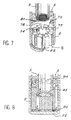
- the exchanger 8 here consists of lobes 77 of massive material in radiating arrangement around a core central 34. Between these lobes 77 are the passages of gases 78 which connect the lower end of the regenerator with the axial volume of the tube 3.
- the gas flow tranquilization laminate which has already been discussed, is represented by a stack of perforated grids 81 mounted in section transverse of the tube 3 at this lower end. These grids can be retained by legs of tube 3, as shown, or just stuck between the end of the tube and the exchanger 8 in its central part limited by a tube centering shoulder 79 3. In all cases, the gas passing between the exchanger lobes is found to have cross the stack of grids.
- This circulation is indicated by arrows in FIG. 8, which relates to another embodiment particularly advantageous especially since it facilitates a tranquilization of the gas flow as close as possible to the cold plate 22.
- the cold exchanger is produced there in two parts 83 and 84 concentrically embossed one in the other; Each has its own material lobes heat exchange alternating with empty areas free to gas circulation. In other words, functionally the exchanger is therefore pierced with channels dividing into two crowns, one under regenerator 5, the other at the end of the tube 3.
- the internal part 83 of the exchanger is shorter than the external part 84 which surrounds it and so that the end of the tube 3 comes center in the part 84 in abutment on the part 83.
- a stack of grids 82 constitutes the laminated to calm the gas flow. These grids are interposed directly against the cold plate 22 between this and the two parts 83 and 84 of the exchanger. In case if necessary, they could be blocked in the exchanger on the outskirts, providing for this purpose a shoulder in the part 84 forming the annular ring of this exchanger.
Description
La présente invention concerne la conception et la réalisation des refroidisseurs cryogéniques qui mettent en oeuvre un gaz de travail suivant un cycle thermodynamique en circuit fermé entre une chambre de compression et une chambre de détente, en passant par un accumulateur thermique dit régénérateur, qui assure un échange de récupération entre gaz chaud comprimé et gaz froid détendu.The present invention relates to the design and production of cryogenic coolers which works a working gas following a thermodynamic cycle in closed circuit between a compression chamber and a expansion chamber, through a thermal accumulator said regenerator, which ensures a recovery exchange between compressed hot gas and expanded cold gas.
Ces refroidisseurs comportent, de manière classique, un oscillateur de pression piloté pour faire varier le volume de la chambre de compression, et un doigt froid se terminant par la chambre de détente, en contact thermique avec un élément à refroidir, placé au fond d'une enveloppe d'isolation thermique. L'élément à refroidir est couramment un composant électronique qu'il s'agit de maintenir en fonctionnement à des températures comprises entre 60 °K et 200 °K, afin notamment d'améliorer le rapport signal sur bruit.These coolers conventionally include a pressure oscillator controlled to vary the volume of the compression chamber, and a cold finger ending with the expansion chamber, in thermal contact with an element to be cooled, placed at the bottom of an envelope thermal insulation. The element to be cooled is commonly an electronic component that must be kept in operation at temperatures between 60 ° K and 200 ° K, in particular to improve the signal to noise.
Dans un tel contexte, qui implique bien des domaines de l'industrie où il est utilisé des composants électroniques ou optoélectroniques, les refroidisseurs cryogéniques du type en question rencontrent un succès chaque jour grandissant, principalement quand ils sont conçus pour être fabriqués à faible coût sous des formes intégrant l'oscillateur de pression avec le doigt froid dans un même ensemble mécanique n'ayant plus besoin de conduites externes pour fermer le circuit de gaz de travail.In such a context, which involves many areas of the industry where electronic components are used or optoelectronics, cryogenic coolers of the type in question are successful each growing day, mainly when they are designed to be manufactured at low cost in forms incorporating the pressure oscillator with the cold finger in one mechanical assembly no longer needing external pipes to close the working gas circuit.
Mais, par ailleurs, la variété de leurs applications industrielles a entraíné le développement de différentes configurations technologiques de refroidisseurs en fonction du cycle de travail le mieux adapté aux circonstances. On les trouvera décrites dans leur principe dans un article de Damien Feger intitulé "Refroidissement des détecteurs optoélectroniques" paru dans "Techniques de l'Ingénieur, traité Electronique" pages E4070-1 à 11. But, moreover, the variety of their applications industrial has led to the development of different technological configurations of chillers in operation of the work cycle best suited to the circumstances. We will find them described in principle in an article by Damien Feger entitled "Cooling of optoelectronic detectors" published in "Engineering techniques, treated Electronics "pages E4070-1 to 11.
Cet article fait déjà état des particularités spécifiques à chaque configuration et des critères présidant au choix de l'une ou l'autre. En relation avec la présente invention, il convient de souligner en particulier que, d'une manière générale, les refroidisseurs du type à tube à gaz pulsé (TGP) pêchent par un rendement inférieur à celui des configurations à cycle de Stirling, alors que quand la notion de rendement perd de son importance, les refroidisseurs à tube à gaz pulsé prennent le pas sur les refroidisseurs à cycle de Stirling. Ne serait-ce que pour des questions de coût, ils ont l'avantage d'impliquer un nombre de pièces plus limité et une exigence moindre dans la réalisation des étanchéités. De ce dernier point de vue, on rappellera que les refroidisseurs à cycle de Stirling comportent un piston dit "déplaceur" qui est monté à coulissement dans le doigt froid terminé par la chambre de détente, d'où le besoin d'une étanchéité au gaz de type dynamique.This article already describes the particularities specific to each configuration and presiding criteria at the choice of one or the other. In connection with this invention, it should be emphasized in particular that, in general, tube type coolers pulsed gas (TGP) fish by a lower yield than that Stirling cycle configurations, when when the notion of efficiency loses importance, chillers with pulsed gas tube take precedence over coolers Stirling cycle. If only for cost issues they have the advantage of involving a number of more limited parts and a lower requirement in the realization of seals. From this last point of view, we recall that Stirling cycle coolers have a piston called "displacer" which is mounted to slide in the cold finger finished by the chamber of trigger, hence the need for gas tightness of the type dynamic.
Les brevets US 3 220 201, US 4 858 442, et 5 293 748, décrivent des exemples de refroidisseur à cycle de Stirling.US patents 3,220,201, US 4,858,442, and 5,293 748, describe examples of a cycle cooler Stirling.
Dans le but de diminuer encore le coût et d'apporter une meilleure souplesse d'utilisation des refroidisseurs dans toutes sortes d'applications, la présente invention se propose principalement de mettre à la disposition des utilisateurs un cryostat qui ne se limite pas à une enveloppe isolante apte à recevoir le doigt froid du refroidisseur, mais qui incorpore une partie de ses organes essentiels, sous une forme permettant leur adaptation interchangeable à différentes configurations.In order to further reduce the cost and provide greater flexibility in the use of coolers in all kinds of applications, the present invention is mainly offers to make available to users a cryostat which is not limited to an envelope insulating capable of receiving the cold finger from the cooler, but which incorporates part of its essential organs, in a form allowing their interchangeable adaptation to different configurations.
Plus précisément, un cryostat pour refroidisseur cryogénique réalisé suivant l'invention s'adapte aisément, conformément à son caractère interchangeable, tant à une configuration à tube à gaz pulsé qu'à une configuration à cycle de Stirling, et que le pilotage de l'oscillateur de pression passe par un entraínement de type rotatif à vilebrequin ou de type linéaire, suivant les expressions utilisées par l'homme de l'art, telles qu'elles sont reprises notamment dans l'article déjà cité.More specifically, a cooler cryostat cryogenic produced according to the invention adapts easily, in accordance with its interchangeable character, both at a pulsed gas tube configuration than a Stirling cycle, and that driving the oscillator of pressure goes through a rotary type drive to crankshaft or linear type, according to the expressions used by those skilled in the art, as they are repeated in particular in the article already cited.
Par ses différentes caractéristiques telles qu'elles seront décrites et revendiquées ci-après, l'invention permet aussi d'apporter des améliorations sensibles à la construction des refroidisseurs intégrant un tel cryostat et à leur mode de pilotage. Les avantages qui en résultent concernent en particulier la combinaison du cryostat avec un oscillateur de pression dans un mode réalisation relevant d'une configuration à tube à gaz pulsé.By its different characteristics as they will be described and claimed below, the invention allows also to make significant improvements to the construction chillers incorporating such a cryostat and their driving style. The resulting benefits relate in particular to the combination of the cryostat with a pressure oscillator in a relevant embodiment of a pulsed gas tube configuration.
En outre, les particularités proposées pour les différents éléments constitutifs des cryostats selon l'invention présentent l'avantage de se prêter particulièrement bien aux modes de fonctionnement respectifs des deux types de refroidisseurs et d'améliorer leurs performances propres. Tel est le cas notamment des dispositions préconisées pour le régénérateur, qui a la charge d'absorber et libérer de la chaleur, alternativement, par rapport au gaz qui le traverse. Tel est le cas également d'un échangeur avantageusement prévu en zone froide, au niveau de la chambre de détente, pour favoriser le transfert thermique vers le composant à refroidir, ainsi que pour un échangeur se situant en zone chaude et sous pression qui est spécialement utile dans les refroidisseurs du type à gaz pulsé, pour favoriser une déperdition thermique vers l'extérieur.In addition, the special features proposed for different components of cryostats according to the invention have the advantage of being particularly suitable well to the respective operating modes of two types of coolers and improve their clean performance. This is particularly the case with the provisions recommended for the regenerator, which is responsible to absorb and release heat, alternatively, by compared to the gas passing through it. This is also the case an exchanger advantageously provided in a cold zone, at level of the relaxation room, to favor the transfer towards the component to be cooled, as well as for a exchanger located in hot zone and under pressure which is especially useful in gas type coolers pulsed, to favor a heat loss towards outside.
Ainsi, l'invention a plus précisément pour objet un cryostat pour refroidisseur cryogénique mettant en oeuvre un circuit fermé de gaz de travail entre une chambre de compression située dans un carter d'oscillateur de pression associé et une chambre de détente située en fond du cryostat, en situation d'échange thermique avec un composant à refroidir, comportant à l'intérieur d'une enveloppe d'isolation thermique, solidaire d'une embase de montage sur ledit carter, un régénérateur thermique interposé sur le circuit du gaz de travail. Ce régénérateur est en disposition annulaire autour d'un volume axial s'étendant entre un échangeur froid qui est en contact thermique avec le composant à refroidir et fait communiquer le régénérateur avec ledit volume axial en fond du cryostat. Le cryostat comporte aussi une couronne de distribution de gaz dans ledit régénérateur, en tête du cryostat, à partir d'un conduit percé à travers l'embase pour connexion à la chambre de compression. La couronne de distribution est formée par une pièce centrale se montant à travers ladite embase axialement en son centre. Ladite pièce centrale est montée de manière amovible dans ladite embase, notamment par vissage étanche. Ceci la rend facilement interchangeable entre un premier modèle pour fonctionnement du volume axial en piston gazeux dans un refroidisseur du type à tube à gaz pulsé, et un second modèle, présentant un alésage axial propre à être traversé par un piston déplaceur de refroidisseur à cycle de Stirling, introduit à coulissement étanche dans le même volume axial. Ainsi, on peut utiliser un même cryostat, construit suivant l'invention, sans rien changer d'autre à son dimensionnement ou à sa fabrication, pour l'intégrer avec un oscillateur de pression adapté de manière à constituer un refroidisseur répondant à l'une ou l'autre de ces configurations majeures.Thus, the invention more specifically relates to a cryostat for cryogenic cooler using a closed working gas circuit between a compression located in a pressure oscillator housing associated and a relaxation room located at the bottom of the cryostat, in heat exchange situation with a component to be cooled, comprising inside an envelope thermal insulation, integral with a mounting base on said housing, a thermal regenerator interposed on the working gas circuit. This regenerator is in annular arrangement around an extending axial volume between a cold exchanger which is in thermal contact with the component to be cooled and makes the regenerator communicate with said axial volume at the bottom of the cryostat. The cryostat also has a gas distribution ring in said regenerator, at the head of the cryostat, from a conduit drilled through the base for connection to the chamber compression. The timing ring is formed by a central piece mounting through said base axially at its center. Said central part is mounted removably in said base, in particular by tight screwing. This makes it easily interchangeable between a first model for operating the axial volume as a gas piston in a gas tube type cooler pulsed, and a second model, with an axial bore suitable for being traversed by a displacement piston Stirling cycle cooler, sliding introduced watertight in the same axial volume. So we can use the same cryostat, built according to the invention, with nothing change other to its dimensioning or its manufacture, to integrate it with a pressure oscillator adapted from so as to constitute a cooler corresponding to one or the other of these major configurations.
Dans la pièce centrale suivant le modèle destiné à un refroidisseur fonctionnant suivant le principe du cycle à gaz pulsé, il est avantageusement ménagé au moins un canal de passage du gaz sous débit contrôlé entre un réservoir tampon de gaz formé à l'intérieur du carter de l'oscillateur de pression, et le volume axial interne au cryostat qui fonctionne en tube à gaz. Il est d'ailleurs avantageux d'y ajouter un ou plusieurs autres canaux à débit contrôlé permettant un prélèvement de gaz chaud directement en sortie de compression, au niveau de la couronne de distribution vers le régénérateur.In the central room following the model intended for a cooler operating on the principle of the pulsed gas, at least one channel is advantageously provided passage of gas under controlled flow between a tank gas buffer formed inside the oscillator housing pressure, and the internal axial volume of the cryostat which works in gas tube. It is also advantageous to add one or more other flow-controlled channels allowing hot gas to be drawn directly at the outlet compression, at the timing ring to the regenerator.
Dans le cas alternatif d'un refroidisseur mettant en oeuvre un cycle de Stirling, le volume interne se trouve au contraire occupé par le piston déplaceur, qui est préférentiellement plein, réalisé en un matériau de faible conductivité thermique, et qui ne laisse libre au gaz que le volume de la chambre de détente au fond du cryostat.In the alternative case of a cooler works a Stirling cycle, the internal volume is at the contrary occupied by the displacer piston, which is preferably solid, made of a weak material thermal conductivity, and which leaves only the volume of the expansion chamber at the bottom of the cryostat.
De préférence, la pièce centrale, avec sa couronne de distribution, est réalisée solidaire d'un tube central limitant ledit volume axial. Ce tube est alors avantageusement de même diamètre interne que l'alésage axial du modèle destiné à un raccordement du cryostat sur un refroidisseur à cycle de Stirling. Il peut donc constituer soit le tube contenant le gaz pulsé dans le premier modèle, soit le tube guide du piston déplaceur du refroidisseur dans le second cas.Preferably, the central piece, with its crown distribution, is made integral with a central tube limiting said axial volume. This tube is then advantageously of the same internal diameter as the axial bore of the model intended for connection of the cryostat to a cooler Stirling cycle. It can therefore constitute either the tube containing the pulsed gas in the first model, namely the guide tube of the cooler displacement piston in the second case.
Suivant une autre caractéristique de l'invention, il est associé au cryostat un échangeur chaud, se positionnant dans le volume interne en tête du cryostat. Son rôle se situe dans l'évacuation des calories qui s'effectue par déperdition thermique vers l'extérieur à travers l'embase et le carter de la partie compresseur du refroidisseur, réalisés à cette fin en matériau thermiquement conducteur. Il est spécialement utile dans la variante de refroidisseur à tube à gaz pulsé, compte tenu de la chaleur à évacuer en sortie du tube à gaz, qui se rajoute à la chaleur emmagasinée par le gaz en retour du régénérateur.According to another characteristic of the invention, it is associated with the cryostat a hot exchanger, positioning in the internal volume at the top of the cryostat. Its role is located in the evacuation of calories which takes place by heat loss to the outside through the base and the casing of the compressor part of the cooler, made for this purpose of thermally conductive material. It is especially useful in the cooler variant with pulsed gas tube, taking into account the heat to be evacuated in gas tube outlet, which adds to the stored heat by the gas back from the regenerator.
En ce qui concerne du moins l'échangeur froid, mais le cas échéant également l'échangeur chaud, l'invention prévoit, suivant une caractéristique secondaire, que l'on peut appliquer avantageusement avec les autres en toute combinaison opérante, d'utiliser une structure à géométrie de révolution, faisant alterner autour de l'axe du cryostat, dans une disposition de marguerite, des zones massives en matériau bon conducteur thermique et des zones vides ouvertes au passage du gaz. En conséquence, ces zones se situent notamment à cheval, de part et d'autre, par rapport à un épaulement de centrage de l'extrémité du tube central.Regarding at least the cold exchanger, but where appropriate also the hot exchanger, the invention foresees, according to a secondary characteristic, that one can apply advantageously with others in any operating combination, to use a geometry structure of revolution, alternating around the axis of the cryostat, in a daisy arrangement, massive areas in material good thermal conductor and void areas open to the passage of gas. As a result, these areas are in particular on horseback, on both sides, in relation to a centering shoulder at the end of the central tube.
Il est souvent avantageux de combiner un tel échangeur froid avec un feuilleté de grilles perforées ayant pour effet d'assurer une tranquillisation du flux gazeux au passage de l'échangeur.It is often advantageous to combine such a cold exchanger with a laminate of perforated grids having the effect of ensuring a tranquilization of the gas flow at passage of the exchanger.
Soulignons encore que dans un refroidisseur suivant l'invention construit pour fonctionner suivant le principe du tube à gaz pulsé, il est avantageux de ménager le volume tampon de gaz alimentant le piston gazeux à l'intérieur d'un piston de compression, qui à cet effet, du côté opposé à la chambre de compression, est directement ouvert dans une chemise de guidage dudit piston qui vient se raccorder sur la pièce centrale appropriée du cryostat.Note again that in a next cooler the invention built to operate on the principle of the pulsed gas tube, it is advantageous to save the volume gas buffer supplying the gas piston inside a compression piston, which for this purpose on the side opposite the compression chamber, is directly opened in a guide sleeve of said piston which is connected to the appropriate center piece of the cryostat.
Pour l'entraínement du piston dans un tel refroidisseur, piston unique de préférence, il est en général souhaitable d'avoir recours à des moyens de pilotage à moteur linéaire, dans la mesure où le coût en est plus faible que pour un pilotage rotatif.For driving the piston in such a cooler, preferably a single piston, it is generally desirable to have recourse to means of piloting linear motor, as far as the cost is more lower than for rotary control.
Dans certaines applications, une configuration du type à moteur rotatif peut cependant se révéler utile. La solution préférée passe alors par des moyens de pilotage comportant un vilebrequin actionnant un mécanisme de transmission de mouvement par roulement à billes mobile dans une gorge ménagée transversalement à l'extérieur dudit piston.In some applications, a configuration of the type with rotary engine can however prove useful. The preferred solution then goes through piloting means comprising a crankshaft actuating a transmission mechanism of movement by movable ball bearing in a groove formed transversely outside said piston.
Quelle que soit la forme de réalisation choisie pour le refroidisseur suivant l'invention, la disposition annulaire du régénérateur se prête particulièrement bien à une fabrication à partir d'une feuille enroulée sur elle-même. En outre, l'invention permet d'améliorer sensiblement l'efficacité des échanges thermiques recherchés, par rapport aux empilements de grilles ou de billes classiques, en utilisant pour cela une feuille en matériau convenable, qui a été au préalable usinée, notamment par procédé photolithographique, de sorte à former des bandes longitudinales distinctes à surface lisse et des barrettes transversales en surépaisseur réunissant ponctuellement les bandes successives.Whatever the embodiment chosen for the cooler according to the invention, the arrangement ring of the regenerator lends itself particularly well to a manufacture from a sheet wound on itself. In addition, the invention makes it possible to significantly improve the efficiency of the heat exchanges sought, compared to stacks of conventional grids or balls, in using for this a sheet of suitable material, which has been previously machined, in particular by photolithographic process, so as to form longitudinal strips with smooth surfaces and transverse bars in extra thickness occasionally joining the strips successive.
Préférentiellement, les différentes bandes se succèdent sur la longueur du régénérateur. Elles forment des couches annulaires de surface lisse entrecoupées par les intervalles entre bandes et les barrettes intercalées entre les couches contribuent à répartir le flux dans toutes les directions à chaque niveau de section transversale.Preferably, the different bands are succeed the length of the regenerator. They form annular smooth surface layers intersected by intervals between bands and bars inserted between the layers help to distribute the flow in all directions at each cross section level.
L'invention sera maintenant plus complètement décrite dans le cadre de caractéristiques préférées répondant au mieux aux propos de l'invention par leurs avantages, en faisant référence aux figures des dessins annexés qui les illustrent et dans lesquelles :
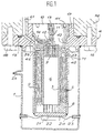
- La figure 1 représente en coupe longitudinale un cryostat suivant l'invention, vu dans ses spécificités plus particulièrement destinées à un accouplement avec un oscillateur de pression de sorte à constituer un refroidisseur cryogénique appliquant un cycle à tube à gaz pulsé ;
- La figure 2 montre les organes principaux du même cryostat, dans une vue éclatée, en s'intéressant au contraire à sa constitution pour accouplement avec l'oscillateur de pression d'un refroidisseur de type à cycle de Stirling ;
- La figure 3 schématise une forme de réalisation préférée du régénérateur thermique, valable dans l'un et l'autre cas ;
- La figure 4 montre une coupe transversale du cryostat au niveau de l'échangeur thermique disposé en zone froide du circuit de gaz de travail, dans la chambre de détente ;
- La figure 5 illustre le montage du cryostat de l'invention, avec sa pièce de distribution interchangeable suivant la figure 2, dans un cas d'application pratique où il sert à constituer un refroidisseur cryogénique à cycle de Stirling suivant l'invention, qui est ici du type à pilotage rotatif ;
- La figure 6 illustre, quant à elle, un autre mode de réalisation de l'invention, fournissant au total un refroidisseur à cycle TGP (tube à gaz pulsé), et elle montre en plus comment se concrétise préférentiellement, conformément à l'invention, un pilotage rotatif dans cette configuration de refroidisseur cryogénique.
- La figure 7 illustre en vue éclatée une conception particulière de l'échangeur froid associé à un feuilleté de grilles de tranquilisation de gaz.
- La figure 8 représente, dans une coupe schématique partielle, une variante de l'échangeur froid faisant appel à une réalisation en deux parties concentriques.
- FIG. 1 represents in longitudinal section a cryostat according to the invention, seen in its specificities more particularly intended for coupling with a pressure oscillator so as to constitute a cryogenic cooler applying a cycle with pulsed gas tube;
- Figure 2 shows the main organs of the same cryostat, in an exploded view, looking instead to its constitution for coupling with the pressure oscillator of a Stirling cycle type cooler;
- Figure 3 shows schematically a preferred embodiment of the thermal regenerator, valid in both cases;
- FIG. 4 shows a cross section of the cryostat at the level of the heat exchanger arranged in the cold zone of the working gas circuit, in the expansion chamber;
- FIG. 5 illustrates the assembly of the cryostat of the invention, with its interchangeable distribution part according to FIG. 2, in a case of practical application where it serves to constitute a cryogenic cooler with a Stirling cycle according to the invention, which is here of the rotary pilot type;
- FIG. 6 illustrates, for its part, another embodiment of the invention, providing a total cooler with a TGP cycle (pulsed gas tube), and it also shows how preferentially takes shape, in accordance with the invention, rotary control in this cryogenic cooler configuration.
- FIG. 7 illustrates in exploded view a particular design of the cold exchanger associated with a laminate of gas stilling grids.
- Figure 8 shows, in a partial schematic section, a variant of the cold exchanger using an embodiment in two concentric parts.
Conformément à l'invention, le cryostat de la figure 1 est utilisé en combinaison avec un oscillateur de pression soit pour constituer un refroidisseur cryogénique de type à gaz pulsé conformément à la figure 6, soit alternativement pour constituer un refroidisseur de type à cycle de Stirling conformément à la figure 5. Dans tous les cas, le refroidisseur ainsi constitué est de construction compacte, le cryostat et l'oscillateur de pression étant intégrés en un même ensemble mécanique.According to the invention, the cryostat of the figure 1 is used in combination with a pressure oscillator either to constitute a cryogenic cooler of the pulsed gas according to Figure 6, or alternatively to constitute a Stirling cycle type cooler as shown in Figure 5. In all cases, the cooler thus constituted is of compact construction, the cryostat and pressure oscillator being integrated in one same mechanical assembly.
Dès la figure 1, on peut observer que le cryostat suivant l'invention ne se limite pas, comme dans les réalisations connues, à une enveloppe d'isolation thermique destinée à recevoir un doigt froid préalablement constitué en tous ses organes fonctionnels nécessaires à la mise en oeuvre du cycle thermodynamique du gaz de travail. Au contraire, les organes fonctionnels passifs, qui ne sont pas soumis à des déplacements en cours de fonctionnement, sont prévus à demeure dans le cryostat, ce dernier étant construit de sorte à pouvoir se raccorder, alternativement au choix de l'utilisateur, au carter d'un oscillateur de pression relevant soit d'un refroidisseur spécifique pour mise en oeuvre d'un cycle de Stirling, soit d'un refroidisseur du type à tube à gaz pulsé.From Figure 1, we can see that the cryostat according to the invention is not limited, as in the embodiments known, to a thermal insulation envelope intended to receive a cold finger previously formed in all its functional organs necessary for the implementation work of the thermodynamic cycle of the working gas. At on the contrary, the passive functional organs, which are not subject to displacement during operation, are permanently installed in the cryostat, the latter being constructed so that it can be connected alternately at the user's choice, at the housing of an oscillator pressure either from a specific cooler for implementation of a Stirling cycle, ie of a cooler of the pulsed gas tube type.
C'est ainsi que dans le cryostat, on trouve, à
l'intérieur d'une enveloppe d'isolation thermique 1 montée
solidaire d'une embase 4 servant à son raccordement
mécanique et pneumatique avec la partie oscillateur de
pression du refroidisseur, deux viroles tubulaires concentriques,
à savoir un tube central 3 et une paroi interne 2
de l'enveloppe 1, qui délimitent entre elles un espace
annulaire occupé par un régénérateur thermique 5. Le régénérateur
5 est ainsi construit en disposition annulaire
autour d'un volume axial 6, limité sur son pourtour par le
tube central 3 parmi les deux viroles précédentes.This is how in the cryostat we find, at
inside a thermal insulation envelope 1 mounted
integral with a
En pratique l'autre virole, qui limite extérieurement
le régénérateur thermique, est donc ici directement
constituée par la paroi interne 2 de l'enveloppe
d'isolation thermique 1. Celle-ci est en effet, de manière
en soi classique, du type à double paroi. Entre ses deux
parois, elle est soit remplie d'un gaz d'inertage à faible
point de condensation, soit soumise à un vide poussé, ce
pour quoi elle est munie d'un port de chargement 25.In practice the other ferrule, which limits externally
the thermal regenerator, so here is directly
formed by the
Dans d'autres réalisations toutefois, mais de
manière généralement moins avantageuse, on préférera
construire le régénérateur 5 avec ses propres enveloppes,
dont une enveloppe externe qui est alors distincte de la
paroi interne 2 de l'enveloppe d'isolation thermique et/ou
une enveloppe interne qui est alors ajoutée contre le tube
central 3.In other embodiments, however, but
generally less advantageous, we prefer
En fond du cryostat, au-delà du régénérateur et de
son enveloppe interne constituée par le tube 3, il est
disposé un échangeur 8, qui constitue en fonctionnement
l'échangeur froid du refroidisseur. Pour cela, cet échangeur
est conçu et disposé de sorte à favoriser le transfert de la
puissance frigorifique résultant de la détente du gaz de
travail vers un composant à refroidir 21, tout en assurant
une communication pneumatique permettant le passage du gaz
de travail entre le fond du volume axial 6 et l'espace
annulaire occupé par le régénérateur 5.At the bottom of the cryostat, beyond the regenerator and
its internal envelope constituted by the
La virole intermédiaire du cryostat de l'invention,
constituée par la paroi 2, est fermée en son extrémité
inférieure, au fond du cryostat, par une plaque transversale
22 contre laquelle est apposé l'échangeur froid 8. Sur sa
face opposée à cet échangeur vient se monter le composant
21, généralement par simple collage.The intermediate shell of the cryostat of the invention,
constituted by the
Quand l'élément à refroidir est constitué, comme
illustré, par un composant électronique 21, par exemple un
détecteur optoélectronique, il est nécessaire de pourvoir à
sa liaison avec un circuit électrique véhiculant les signaux
qu'il reçoit ou qu'il émet. On a donc fait apparaítre sur la
figure 1, une couronne de distribution électrique 23, dont
les parties conductrices passent par des traversées étanches
à travers la paroi externe de l'enveloppe d'isolation
thermique 1, ainsi que des fils conducteurs 24 qui les
relient ensuite au composant 21.When the element to be cooled is constituted, as
illustrated, by an
L'enveloppe 1 dans son ensemble a pour fonction de limiter les pertes thermiques par radiation ou convection au niveau des organes intervenant dans le cycle thermodynamique du refroidisseur complet dans la zone froide de celui-ci. The envelope 1 as a whole has the function of limit heat losses by radiation or convection to level of organs involved in the thermodynamic cycle of the complete cooler in the cold zone thereof.
Ainsi qu'il apparaít sur la figure 1, sa paroi
externe est soudée en sous-face de l'embase 4, tandis que sa
paroi interne 2 est monolithique avec celle-ci. L'une et
l'autre peuvent être réalisées en acier inoxydable.As it appears in Figure 1, its wall
outer is welded on the underside of the
Cependant, on peut aussi choisir, pour la paroi interne 2, une qualité d'acier inoxydable correspondant à un alliage à faible conductivité thermique, adaptée pour être compatible avec le gaz de travail utilisé, lequel est préférentiellement l'hélium dans le cas du régénérateur à feuille métallique enroulée comme décrit plus loin.However, we can also choose, for the wall internal 2, a quality of stainless steel corresponding to a alloy with low thermal conductivity, adapted to be compatible with the working gas used, which is preferably helium in the case of the regenerator at metallic foil rolled up as described below.
La paroi extérieure de l'enveloppe 1 est réalisée également en acier inoxydable, ou éventuellement en une qualité appropriée de verre, pour des raisons d'ordre économique.The outer wall of the envelope 1 is produced also in stainless steel, or possibly in one appropriate quality of glass, for economic reasons.
Suivant le matériau choisi, il peut donc être nécessaire d'avoir recours à des jonctions verre/métal pour assurer l'étanchéité des soudures et des traversées électriques, ce qui toutefois posera d'autant moins de problèmes à l'homme de l'art que ce besoin se situe en des endroits sous pression statique.Depending on the material chosen, it can therefore be necessary to use glass / metal junctions for sealing of welds and bushings electric, which will however pose all the less problems to those skilled in the art that this need lies in places under static pressure.
En tête du cryostat, à l'extrémité supérieure de
l'enveloppe thermiquement isolante 1 et du régénérateur 5,
l'embase 4 se trouve au contraire en zone chaude du refroidisseur
en fonctionnement, là où règne aussi une pression
dynamique du gaz de travail, soumise à des pulsations de
pression périodiques, imprimées par les éléments mobiles du
refroidisseur lorsque le cryostat est raccordé au carter 50
d'un oscillateur de pression associé.At the head of the cryostat, at the upper end of
the thermally insulating envelope 1 and of the
Dans cette zone chaude, il convient d'évacuer les
calories du gaz revenant de la détente, après la récupération
effectuée dans le régénérateur 5. Pour cela, il est
prévu de réaliser l'embase 4 en un matériau de bonne conductivité
thermique, généralement de l'acier inoxydable, sous
une forme favorisant les déperditions vers l'extérieur.In this hot zone, the
calories from gas returning from trigger after recovery
performed in
Dans l'embase 4 on distingue une collerette
circulaire 16, percée de trous pour le passage des vis 48
assurant la fixation sur le carter 50 du refroidisseur, qui
vient se raccorder en appui sur la face supérieure de la
collerette 16, opposée à l'enveloppe thermique 1. On
distingue aussi une bague 17, faisant partie de l'embase 4,
qui assure le centrage des deux éléments l'un dans l'autre.
Le raccordement étanche de ces deux éléments (cryostat et
oscillateur de pression) vis-à-vis de l'extérieur est assuré
par un joint 19, logé dans une gorge annulaire de la face
supérieure de la collerette 16.In the
L'embase 4 livre passage, dans l'axe du système, à
une pièce centrale 10, vissée de manière étanche dans la
bague 17, laquelle est filetée intérieurement. Une gorge
hexagonale 41, ménagée dans sa face plane supérieure, sert à
sa manipulation lors du montage.The
Comme on l'a déjà expliqué, cette pièce centrale du
cryostat est conçue sous deux modèles différents qui, par
leur géométrie extérieure, leur dimensionnement, et leur
conception fonctionnelle, sont interchangeables dans une
même construction de cryostat. Les deux modèles sont
illustrés par la figure 1 et par la figure 2, suivant que le
cryostat 30 est monté pour être accouplé avec les carters 50
ou 60 de l'un ou l'autre des deux oscillateurs de pression
dans les deux variantes de refroidisseur montrées sur les
figures 6 et 5 respectivement.As already explained, this central piece of the
cryostat is designed in two different models which, by
their external geometry, their dimensioning, and their
functional design, are interchangeable in one
same construction of cryostat. Both models are
illustrated by FIG. 1 and by FIG. 2, depending on whether the
Dans tous les cas, cette pièce centrale, donc en
particulier celle portant la référence 10 sur la figure 1,
est ici constituée d'une seule pièce avec le tube interne 3
du cryostat. In any case, this central part, therefore in
in particular that bearing the
D'autre part, elle forme une couronne de distribution
71, pour la répartition annulaire du gaz en tête du
régénérateur 5. En conséquence, cette couronne se place au-dessus
de celui-ci (dans la disposition verticale représentée,
cryostat sous le carter 50), et plus précisément au
centre de l'embase 4 en sa partie principale formée par la
collerette 16.On the other hand, it forms a
Dans le mode de réalisation illustré, la couronne de
distribution 71 présente une gorge circulaire 45, creusée
dans sa face inférieure, qui vient en butée sur le régénérateur
5. Cette gorge communique par des orifices 46 avec
une chambre annulaire 43, prolongée vers le haut en 42, qui
est ménagée extérieurement dans la partie de la pièce
centrale 10 se trouvant au niveau de la collerette 16, entre
cette pièce et la face en vis-à-vis de l'embase 4.In the illustrated embodiment, the crown of
C'est là que débouche un canal 39, percé à travers
cette collerette de l'embase 4 jusqu'à communiquer, une fois
le montage du refroidisseur terminé, avec un conduit 61 par
lequel s'effectue la liaison pneumatique avec la chambre de
compression située dans l'oscillateur de pression.This is where a
Pour le reste, la pièce centrale 10 est représentée
sur la figure 1 dans le modèle convenant pour un refroidisseur
type TGP illustré par la figure 6.For the rest, the
Le second modèle de pièce centrale du cryostat,
destiné lui à un refroidisseur à cycle Stirling, est montré
sur la représentation schématique en disposition éclatée de
la figure 2. Dans ce cas, le pièce centrale 20 est identique
à la précédente extérieurement, mais intérieurement, elle
comporte simplement un alésage axial 72, ménagé tout du long
à travers elle, au même diamètre que le tube 3 dont elle
prolonge le volume central. The second model of central part of the cryostat,
intended for a Stirling cycle cooler, is shown
on the schematic representation in exploded layout of
Figure 2. In this case, the
En revenant à la figure 1, on observe la constitution
des moyens d'alimentation du piston gazeux occupant
le volume interne 6 du cryostat. A l'entrée de celui-ci
débouche un canal 11, qui est percé axialement dans la pièce
centrale 10 jusqu'à sa face supérieure, où il se termine par
un orifice calibré 13 imposant un débit gazeux contrôlé.Returning to Figure 1, we observe the constitution
means for supplying the occupying gas piston
the
Une autre liaison pneumatique, impliquant un ou
plusieurs canaux, est assurée à travers la pièce 10, avec la
chambre annulaire 43 de la couronne de distribution de gaz
vers le régénérateur 5. on a ainsi fait apparaítre un
orifice calibré 14, sur un canal 12 débouchant dans le canal
axial 11.Another pneumatic connection, involving one or
several channels, is ensured through
Les orifices calibrés des canaux 11-12 fonctionnent,
de manière en soi classique, comme des vannes introduisant
des impédances pneumatiques. Le canal principal 11 ainsi
équipé procure en fonctionnement le déphasage utile entre
l'onde de pression générée par l'oscillateur de pression et
les variations de débit en résultant dans le tube contenant
le gaz pulsé. L'impédance secondaire (canal 12) permet
d'apporter une fraction du débit d'alimentation périodique
du tube en la prélevant directement en sortie de
compression, par dérivation de la circulation passant à
travers le régénérateur et le tube. Ceci diminue la charge
thermique sur le régénérateur et contribue à améliorer
l'efficacité du refroidisseur, dans le cas d'un cycle à gaz
pulsé.The calibrated orifices of channels 11-12 are working,
in a conventional manner in itself, like valves introducing
pneumatic impedances.
La figure 1 montre enfin un échangeur 9, situé en
zone chaude dans le volume central, au niveau de la couronne
de distribution 71. Cet échangeur chaud peut éventuellement
être réalisé de manière analogue à ce qui sera décrit plus
loin pour l'échangeur froid, l'essentiel étant que, dans
cette variante de réalisation du cryostat de l'invention, il
vienne parfaire l'évacuation des calories excédentaires du
cycle thermodynamique en complétant, à partir de la zone
chaude du tube de gaz pulsé, les déperditions thermiques
vers l'extérieur ayant lieu par le biais de l'embase 4, et
accessoirement du carter d'oscillateur de pression associé.FIG. 1 finally shows an
Pour l'un et l'autre des deux types de refroidisseurs,
le régénérateur thermique 5 est avantageusement
constitué, comme il apparaít des figures 1 et 3, de manière
à jouer pleinement son rôle d'accumulateur thermique pour la
récupération ayant lieu, de manière en soi classique, entre
le gaz de travail passant de la phase de compression à la
phase de détente et le gaz de travail passant de la phase de
détente à la phase de compression.For either of the two types of coolers,
the
Dans le mode de réalisation préférentiel de
l'invention décrit ici et illustré par la figure 3, un tel
régénérateur se présente sous la forme d'une feuille
continue qui est enroulée en une série de spires autour du
tube central 3 qui limite le volume interne 6 du régénérateur,
de manière à remplir, aussi complètement qu'il est
possible dans la pratique industrielle, l'espace annulaire
compris entre ce tube 3, qui forme sa virole enveloppe
interne, et sa virole enveloppe externe associée, constituée
par la paroi interne 2 de l'enveloppe isolante 1.In the preferred embodiment of
the invention described here and illustrated by FIG. 3, such
regenerator comes in the form of a leaf
continuous which is wound in a series of turns around the
Les procédés d'usinage par photolithographie, qui sont connus en eux-mêmes, sont particulièrement intéressants en ce sens, dans la mesure où ils représentent des moyens technologiques particulièrement simples à mettre en oeuvre pour un prix de revient limité, quand il s'agit de conduire à la configuration illustrée par le détail de la figure 3.Machining processes by photolithography, which are known in themselves, are particularly interesting in this sense, insofar as they represent means particularly simple to implement for a limited cost price, when it comes to driving to the configuration illustrated by the detail in FIG. 3.
Suivant cette configuration, la feuille qui est
ainsi enroulée en spires consécutives jointives, forme une
succession de bandes longitudinales distinctes 27, qui
s'orientent perpendiculairement à l'axe du cryostat et qui
sont séparées les unes des autres par des intervalles 28.
Des barrettes 26 sont formées en surépaisseur des bandes et
en travers de celles-ci dans le sens perpendiculaire. Elles
sont régulièrement réparties sur toute la longueur et la
hauteur de la feuille et disposées en quinconce, chacune
réunissant deux bandes successives par dessus l'intervalle
qui les sépare.According to this configuration, the sheet which is
thus wound in contiguous consecutive turns, forms a
succession of separate
On réalise de cette manière, à la fois des couches
de surfaces lisses qui seront léchées par le gaz de travail
suivant son sens global de circulation sous l'effet des
différences de pression mais qui sont périodiquement
interrompues par les intervalles 28, et des barrières
orientées transversalement aux bandes et aux intervalles
entre deux spires consécutives de la feuille. Ceci permet
d'obtenir une bonne distribution du gaz entre les couches,
équilibrée dans toutes les directions d'une section
transversale du régénérateur, ainsi que d'éviter
l'apparition d'instabilités préjudiciables à l'efficacité
des échanges, tout en créant la perte de charge importante
qui est nécessaire au déphasage dans le pilotage de certains
refroidisseurs.In this way, we realize both layers
smooth surfaces which will be licked by the working gas
according to its overall direction of circulation under the effect of
pressure differences but which are periodically
interrupted by
En ce qui concerne le dimensionnement géométrique
d'un régénérateur ainsi construit, on peut citer en exemple
le cas dune feuille de 100 à 200 microns d'épaisseur,
creusée à mi-épaisseur par chaque face, pour un régénérateur
de 2 à 3 millimètres d'épaisseur radiale. Les bandes et les
intervalles entre elles peuvent, par exemple, être d'une
même largeur, de l'ordre de 50 à 100 microns. La longueur
transversale des barrettes 26 peut correspondre, ici encore
à titre d'exemple, à 1,5 fois le pas de répétition des
bandes longitudinales 27, avec une largeur environ moitié
moindre et une distance entre deux barrettes successives
décalées, équivalente à environ trois fois la largeur de
chacune.Regarding the geometric design
of a regenerator thus constructed, we can cite as an example
the case of a sheet 100 to 200 microns thick,
hollowed out halfway through each side, for a regenerator
from 2 to 3 millimeters in radial thickness. The tapes and
intervals between them can, for example, be of a
same width, of the order of 50 to 100 microns. The length
transverse of the
L'invention permet ainsi de tirer profit d'un rapport entre l'échange convectif local et les pertes de charges longitudinales qui, dans le cas de plaques parallèles à l'axe du doigt froid, serait supérieur à la valeur que l'on peut obtenir par les empilements usuels de grilles ou de billes, cependant que, sous cette forme de réalisation pratique, elle permet d'assurer une meilleure distribution du débit de gaz entre les couches parallèles de surfaces lisses.The invention thus makes it possible to take advantage of a relationship between local convective exchange and losses of longitudinal loads which, in the case of plates parallel to the axis of the cold finger, would be greater than the value that can be obtained by the usual stacks of grids or balls, however that in this form of practical realization, it ensures better distribution of the gas flow between the parallel layers of smooth surfaces.
De la sorte, on parvient à équilibrer le débit de gaz de travail circulant entre les couches annulaires à surface parallèle à l'axe du cryostat de l'invention, et le débit de gaz circulant transversalement, dans toutes les directions radiales du régénérateur aux différents niveaux entre bandes successives. En conséquence, on évite les différences qui existent dans les régénérateurs connus entre le débit radial et le débit axial, alors que l'on peut constater qu'une telle différence de répartition entraíne des transferts thermiques déséquilibrés qui dégradent les performances des régénérateurs.In this way, we manage to balance the flow of working gas flowing between the annular layers at surface parallel to the axis of the cryostat of the invention, and the gas flow circulating transversely, in all radial directions of the regenerator at the different levels between successive bands. As a result, we avoid differences that exist in known regenerators between the radial flow and the axial flow, while we can find that such a difference in distribution results unbalanced heat transfers which degrade performance of regenerators.
La présence des barrières 26, qui restent de faibles
dimensions en regard de la longueur et de l'épaisseur du
régénérateur, permet en outre d'introduire une interruption
périodique du flux longitudinal entre les couches de bandes
successives d'un bout à l'autre du régénérateur, et par là
de stabiliser le débit gazeux global. Simultanément, comme
ces barrettes jouxtent deux couches adjacentes de bandes, on
obtient grâce à elles une réduction des pertes d'énergie
thermique par conduction dans le sens longitudinal. Simultanément,
on assure ainsi une réduction des pertes d'énergie
thermique par conduction dans le sens longitudinal.The presence of
Par là même, on résout les problèmes qui, dans les refroidisseurs connus, sont liés aux variations de la viscosité du gaz de travail en fonction de la température locale, et qui causent des variations entraínant une instabilité intrinsèque du débit de gaz, et ainsi une faible efficacité du régénérateur.In this way, we solve the problems which, in the known coolers, are linked to variations in the viscosity of the working gas as a function of the temperature local, and which cause variations causing instability intrinsic gas flow, and thus a low efficiency of the regenerator.
Une telle réalisation du régénérateur 5 permet,
dune façon particulièrement avantageuse dans le cadre de la
présente invention, d'obtenir un rapport entre l'échange
convectif local et la perte de charge longitudinale très
avantageux, tout en améliorant la distribution du débit de
gaz entre les couches parallèles orientées longitudinalement,
jusqu'à atteindre des performances de récupération
thermique au moins équivalentes, si ce n'est supérieures à
celles que l'on sait obtenir dans les réalisations connues
par des régénérateurs à grilles transversales empilées ou à
billes.Such an embodiment of the
Une autre caractéristique commune aux deux variantes
de refroidisseurs décrites ici, à titre d'exemples, concerne
la réalisation de l'échangeur froid 8 mis en place en fond
de l'enveloppe d'isolation thermique 1 du cryostat suivant
l'invention, telle qu'elle est illustrée plus particulièrement
par la figure 4.Another characteristic common to both variants
of coolers described here, by way of example, relate
the realization of the
On remarquera tout d'abord que, lors de la mise en
place de la pièce centrale 10 ou 20 dans le cryostat, son
centrage est assuré au niveau de la couronne de distribution
71, directement dans l'axe de l'embase 4 et sur la paroi
interne 2 de l'enveloppe 1, jusqu'à pousser le regénérateur
5 en butée sur l'échangeur froid 8. Dans la mesure où elle
porte avec elle le tube central 3, cette pièce centrale est
également centrée, à l'extrémité de ce dernier, grâce à un
épaulement 34 formé en face supérieure de l'échangeur 8.It will be noted first of all that, when setting
place of the
Cet échangeur froid est réalisé, conformément à ce qui ressort des figures 1, 2 et 4, sous une forme dite en marguerite. Il est constitué par une structure à géométrie de révolution, qui est réalisée en un matériau fortement conducteur tel que du cuivre ou de l'aluminium. This cold exchanger is produced in accordance with this which emerges from Figures 1, 2 and 4, in a form called Daisy. It is constituted by a structure with geometry of revolution, which is made of a material strongly conductor such as copper or aluminum.
Cette structure fait alterner en étoile autour d'un
noyau central 31, des zones vides 32 creusées à travers son
épaisseur longitudinale et des zones massives 33 assurant la
conduction thermique. Les unes et les autres s'étendent
radialement à cheval par rapport à l'épaulement 34, de part
et d'autre de l'extrémité du tube central 3. Elles laissent
donc le gaz circuler librement entre le volume central 6 du
cryostat (ou du moins la chambre de détente restant en fond
du cryostat dans le cas d'un refroidisseur suivant la figure
5 appliquant un cycle de Stirling), en contournement de
l'extrémité inférieure du tube central 3 reçue dans
l'épaulement 34.This structure alternates in a star around a
central core 31,
Un tel échangeur miniature, sous par exemple 5 mm de diamètre et 3 mm d'épaisseur, peut être fabriqué aisément par usinage électrochimique d'un barreau cylindrique, qui est ensuite découpé en tronçons.Such a miniature exchanger, for example under 5 mm diameter and 3 mm thick, can be manufactured easily by electrochemical machining of a cylindrical bar, which is then cut into sections.
Il permet d'apporter une surface d'échange
importante pour un encombrement réduit, et sans créer de
pertes de charge perturbatrices, tout en assurant une
tranquillisation bénéfique en fond du tube 3 dans le cas où
il reçoit du gaz pulsé. Aux fins de mieux tranquilliser le
flux gazeux des feuilletés de grilles perforés sont
interposés entre le tube 3 et les lobes de l'échangeur. Ils
n'ont pas été représentés sur la figure 3.It provides an exchange surface
important for a small footprint, and without creating
disruptive pressure losses, while ensuring
beneficial tranquilization at the bottom of
Les mêmes avantages se retrouvent si les zones
rayonnantes alternativement pleines et vides sont
interverties. Le noyau 31 peut être en plus percé d'un
passage vide en son centre, et il n'est pas nécessaire de
laisser subsister une couronne périphérique de matériau,
jointive en continu avec le tube central 3. Les zones
massives forment des lobes de matériau échangeur, ici encore
dans une configuration à cheval par rapport au diamètre du
tube 3, dans laquelle les zones vides entre les lobes
assurent le passage du gaz entre le régénérateur et soit la
chambre de détente d'un refroidisseur à cycle Stirling, soit
le fond du piston gazeux d'un refroidisseur à tube à gaz
pulsé.The same benefits are found if the areas
alternately full and empty radiant are
inverted. The core 31 can also be pierced with a
empty passage in its center, and there is no need to
leave a peripheral crown of material,
contiguous continuously with the
La figure 5 illustre la combinaison du cryostat des
figures précédentes, utilisant la pièce centrale 20 de la
figure 2, avec un oscillateur de pression répondant à la
configuration d'un refroidisseur à cycle Stirling, dans
lequel le pilotage est à moteur rotatif.FIG. 5 illustrates the combination of the cryostat of the
previous figures, using the
On a représenté schématiquement un système
d'entraínement classique par un vilebrequin 51 dont
l'excentrique est lié à deux bielles 53, 54, disposées à 90
degrés l'une de l'autre. A l'intérieur du carter 60, la
bielle 53 est articulée sur l'extrémité du piston déplaceur
55, tandis que la bielle 54 est articulée sur le piston de
compression 56 qui limite la chambre de compression 57. Le
gaz comprimé est véhiculé par des conduits 58, 59 jusqu'au
canal 39 du cryostat alimentant la chambre de distribution
71 du cryostat, et de là le régénérateur 5.We have schematically represented a system
classic drive by a
Le piston déplaceur 55 est mobile axialement dans le
volume interne 6 du cryostat 30. Il occupe quasiment tout ce
volume, en ne laissant place au fond du tube 3 qui constitue
son guide, qu'à l'épaisseur de la chambre de détente,
considérablement agrandie sur la figure par rapport à la
réalité pratique.The
Il passe donc par l'alésage axial 72 de la pièce
centrale 20. Son coulissement dans celle-ci est assuré sous
étanchéité au gaz par un revêtement adapté appliqué sur sa
surface périphérique.It therefore passes through the
La figure 6 utilise au contraire un oscillateur de
pression conçu pour un refroidisseur type TGP dont le carter
50 est raccordé sur le cryostat autour de la pièce centrale
10 du modèle de la figure 1. Figure 6 on the contrary uses an oscillator of
pressure designed for a TGP type cooler including the
On voit donc sur cette figure 6 que l'échangeur
chaud 9 est présent et que le volume interne 6 du cryostat
est resté vide pour être occupé par le gaz pulsé et
fonctionner comme un piston gazeux.We therefore see in this figure 6 that the exchanger
hot 9 is present and the
Dans le cas particulier illustré, le mode de
pilotage est de type rotatif. L'arbre moteur est perpendiculaire
à l'axe du système et, par un vilebrequin à axe
décentré 66, il entraíne dans un mouvement oscillant, un
piston unique 74.In the particular case illustrated, the mode of
piloting is of rotary type. The motor shaft is perpendicular
to the axis of the system and, by an axis crankshaft
off
Le piston 74 est mobile, verticalement sur la
figure, dans l'axe du cryostat, dans une chemise formée à
l'intérieur du carter 50.The
Sur l'axe décentré 66 est montée la cage interne 68
d'un roulement à billes, dont la cage externe 67 est
emprisonnée dans une gorge rectiligne 75 creusée latéralement
dans la surface périphérique du piston 74,
perpendiculairement à son axe et au plan de la figure. Cette
disposition permet d'assurer le mouvement alternatif du
piston tout en l'immobilisant en rotation.On the offset
La chambre de compression 63 est ménagée entre la
face d'extrémité supérieure du piston et le carter 60. Elle
est reliée, comme dans le cas précédent, par un perçage 62
et un conduit 61 au canal 39 débouchant dans la chambre de
distribution du cryostat.The
La face opposée du piston est creuse. on ménage
ainsi, du côté opposé à la chambre de compression, un
réservoir 65, de volume important par rapport au volume de
gaz en circulation. La pression régnant dans ce réservoir
reste donc pratiquement constante en fonctionnement.The opposite side of the piston is hollow. we clean
thus, on the side opposite to the compression chamber, a
C'est ainsi que le piston 74 ménage là, à
l'intérieur de sa chemise de guidage, un réservoir qui est
directement ouvert sur la partie centrale du cryostat et qui
remplit la fonction de volume tampon pour la vanne sous
débit contrôlé constituée par l'orifice calibré 13 de la
figure 1, à l'alimentation du piston gazeux occupant la
volume central 6.This is how the
Conformément à une variante de réalisation pratique
restant dans le cadre de l'invention, on peut avantageusement
appliquer la même disposition, ménageant le
réservoir tampon, directement ouvert sur la surface libre de
la pièce centrale 10 en tête du cryostat, à l'intérieur du
piston de compression, dans le cas d'un refroidisseur de
type TGP dont le pilotage est assuré par moteur linéaire
plutôt que par moteur rotatif.According to a practical variant
remaining within the scope of the invention, it is advantageously possible
apply the same arrangement, sparing the
buffer tank, directly open on the free surface of
the
Sur la figure 7 on a fait apparaítre une variante de
réalisation particulièrement avantageuse pour le fond du
cryostat. La représentation éclatée, utilisée pour plus de
clarté, montre schématiquement le régénérateur 5 entre le
tube 3 de gaz pulsé et la paroi tubulaire 2, qui laisse
place à l'échangeur froid 8 contre la plaque 22.In Figure 7 we have shown a variant of
particularly advantageous for the bottom of the
cryostat. Exploded representation, used for more than
clarity, schematically shows the
L'échangeur 8 est ici constitué de lobes 77 de
matériau massif en disposition rayonnante autour d'un noyau
central 34. Entre ces lobes 77 se situent les passages de
gaz 78 qui font communiquer l'extrémité inférieure du
régénérateur avec le volume axial du tube 3.The
Le feuilleté de tranquillisation du flux gazeux,
dont il a déjà été question, est représenté constitué par un
empilement de grilles perforées 81 monté en section
transversale du tube 3 à cette extrémité inférieure. Ces
grilles peuvent être retenues par des pattes du tube 3,
comme représenté, ou simplement coincées entre le bout du
tube et l'échangeur 8 dans sa partie centrale limitée par un
épaulement 79 de centrage du tube 3. Dans tous les cas, le
gaz passant entre les lobes de l'échangeur se trouve devoir
traverser l'empilement de grilles.The gas flow tranquilization laminate,
which has already been discussed, is represented by a
stack of
Cette circulation est matérialisée par des flèches
sur la figure 8, qui concerne un autre mode de réalisation
particulièrement avantageux dans la mesure notamment où il
facilite une tranquillisation du flux gazeux au plus près de
la plaque froide 22. L'échangeur froid y est réalisé en deux
parties 83 et 84 emboltées concentriquement l'une dans
l'autre; Chacune présente ses propres lobes de matériau
d'échange thermique alternant avec des zones vides libres à
la circulation gazeuse. Autrement dit, fonctionnellement
l'échangeur est donc percé de canaux se répartissant en deux
couronnes, l'une sous le régénérateur 5, l'autre en bout du
tube 3. On voit en plus que la pièce interne 83 de
l'échangeur est plus courte que la pièce externe 84 qui
l'entoure et que, de la sorte, le bout du tube 3 vient se
centrer dans la pièce 84 en butée sur la pièce 83.This circulation is indicated by arrows
in FIG. 8, which relates to another embodiment
particularly advantageous especially since it
facilitates a tranquilization of the gas flow as close as possible to
the
Un empilement de grilles 82 constitue le feuilleté
de tranquillisation du flux gazeux. Ces grilles sont
interposées directement contre la plaque froide 22 entre
celle-ci et les deux pièces 83 et 84 de l'échangeur. En cas
de besoin, elles pourraient être bloquées dans l'échangeur
en périphérie, en ménageant à cet effet un épaulement dans
la pièce 84 formant la couronne annulaire de cet échangeur.A stack of
Claims (15)
- Cryostat for a cryogenic cooler using a closed working-gas circuit between a compression chamber located in an associated pressure oscillator casing and an expansion chamber located at the bottom of the cryostat, in a situation of heat exchange with a component to be cooled, comprising, inside a thermal insulation envelope (1), secured to a mounting baseplate (4) on the said casing (50, 60), a heat regenerator (5) inserted on the circuit of the working gas, in an annular arrangement around an axial volume (6) lying between a cold exchanger (8) which is in thermal contact with the component to be cooled (21) and which makes the regenerator (5) communicate with the said axial volume at the bottom of the cryostat (30), characterized in that it comprises a ring (71) for distributing gas in the said regenerator (5), at the top of the cryostat, from a pipe (39) drilled through the baseplate (4) for connection to the compression chamber, the said distribution ring (71) being formed by a central part (10, 20) mounted detachably and through the said baseplate (4) axially at its centre, and interchangeable between a model suitable for a cooler of the pulsed-gas type in which the axial volume (6) operates as a gas piston and a model suitable for a cooler of the Stirling cycle type in which a displacer piston moves in the said axial volume.
- Cryostat according to Claim 1, characterized in that the said central piece, with the said distribution ring (71), is secured to a tube (3) limiting the said axial volume (6).
- Cryostat according to either of Claims 1 and 2, characterized in that the said central part has, in the model suitable for a cooler of the Stirling cycle type, an axial bore capable of being traversed by a displacer piston of the cooler, inserted so that it can slide in a sealed manner in the said axial volume (6).
- Cryostat according to any one of Claims 1 to 3, characterized in that the said cold exchanger (8) has a structure with axisymmetric geometry, making solid regions (33) made of a good thermal conductor alternate around the axis of the cryostat with empty regions (32) open to the passage of the gas.
- Cryostat according to Claim 4, characterized in that the said empty regions (33) lie on each side of a shoulder (34) for centring a central tube (3) limiting the said axial volume.
- Cryostat according to any one of Claims 1 to 5, characterized in that the said thermal insulation envelope (1) has an inner tubular wall (2) contiguous with the regenerator, closed by a plate (22) accommodating the component to be cooled, to which the cold exchanger (8) is fixed.
- Cryostat according to any one of Claims 1 to 6, characterized in that the said regenerator consists of a sheet wound over itself in the annular space between an inner wall (2) of the said envelope (1) and a central tube (3) limiting the said axial volume, in alignment with the said distribution ring, the said sheet being machined, in particular by a photolithographic process, so as to form distinct strips (27) with smooth surfaces parallel to the axis of the cryostat and transverse bars (26) in the form of an overthickness bringing together the successive strips at discrete points.
- Cryostat according to any one of Claims 1 to 7, characterized in that the said distribution ring has a lower face for stopping on the said regenerator, in which face a circular groove (45) is hollowed out, communicating via regularly spaced orifices with an annular chamber (42, 43) made externally around the said central part at the level of the baseplate (4) of the cryostat, in communication with the said channel (39).
- Cryostat according to any one of Claims 1 to 8, characterized by a lamination of grids for calming the gas stream inserted at the bottom of the said axial volume against the cold exchanger.
- Cryostat according to any one of Claims 1 to 9, characterized in that the said baseplate (4) forms a ring (17) for mounting the said central part (10, 20), in alignment with the said axial volume (6).
- Cooler, characterized in that it comprises a cryostat according to any one of Claims 1 to 10 corresponding to the model suited for a Stirling cycle cooler, connected to the casing (60) of a pressure oscillator comprising a displacer piston driven in a synchronized manner so that it is out of phase with a compression piston and in that the said displacer piston (55) is able to move axially in the said inner volume (6) of the cryostat (30) and then changes to sliding in a sealed manner in an axial bore (72) provided for this purpose in the said central part (20) mounted in the said baseplate of the cryostat.
- Cooler, characterized in that it comprises a cryostat according to any one of Claims 1 to 10 corresponding to the model suited for a pulsed-gas cooler, connected to the casing (50) of a pressure oscillator comprising means for periodically driving a piston for compressing the gas causing the volume of the compression chamber and a buffer reservoir of gas at constant pressure to vary, and in that the said central part (10) mounted in the baseplate (4) of the cryostat comprises means for pneumatic connection at a controlled flow rate with the said reservoir (65).
- Cooler according to Claim 12, characterized in that the said central part comprises, in addition to a channel (11) for the passage of the gas at a controlled flow rate between the said buffer reservoir of gas at constant pressure made inside the casing (50) of the pressure oscillator, and the said internal axial volume (6) of the cryostat, the latter being filled with gas in operation in order to form a gas piston out of phase with respect to the periodic compression, at least one other channel (12) with a controlled flow rate, opening out into an annular chamber (42, 43) formed by the said central part (10) made according to Claim 8.
- Cooler according to Claim 12 or 13, characterized in that the said buffer volume of gas is made inside a compression piston controlled by the said drive means, which is for this purpose directly open, in a liner for guiding the said piston, on the said central part (10) of the cryostat.
- Cooler according to any one of Claims 12 to 14, characterized in that, in a configuration of the rotary engine type, the said drive means comprise a crankshaft actuating a mechanism for transmitting movement by means of ball bearings which is able to move in a groove made transversely outside the said piston.
Applications Claiming Priority (2)
| Application Number | Priority Date | Filing Date | Title |
|---|---|---|---|
| FR9605086 | 1996-04-23 | ||
| FR9605086A FR2747767B1 (en) | 1996-04-23 | 1996-04-23 | CRYOSTAT FOR CRYOGENIC COOLER AND COOLERS COMPRISING SUCH A CRYOSTAT |
Publications (2)
| Publication Number | Publication Date |
|---|---|
| EP0803687A1 EP0803687A1 (en) | 1997-10-29 |
| EP0803687B1 true EP0803687B1 (en) | 2002-06-26 |
Family
ID=9491490
Family Applications (1)
| Application Number | Title | Priority Date | Filing Date |
|---|---|---|---|
| EP19970400898 Expired - Lifetime EP0803687B1 (en) | 1996-04-23 | 1997-04-22 | Cryostat for cryogenic refrigerator and refrigerators comprising such a cryostat |
Country Status (3)
| Country | Link |
|---|---|
| EP (1) | EP0803687B1 (en) |
| DE (1) | DE69713547T2 (en) |
| FR (1) | FR2747767B1 (en) |
Families Citing this family (5)
| Publication number | Priority date | Publication date | Assignee | Title |
|---|---|---|---|---|
| JP3751175B2 (en) * | 1999-12-21 | 2006-03-01 | シャープ株式会社 | Stirling refrigerator |
| FR2815700B1 (en) * | 2000-10-19 | 2004-10-22 | Sagem | CLY CYCLE CRYOGENIC DEVICE |
| KR100393792B1 (en) * | 2001-02-17 | 2003-08-02 | 엘지전자 주식회사 | Pulstube refrigerator |
| US8910486B2 (en) | 2010-07-22 | 2014-12-16 | Flir Systems, Inc. | Expander for stirling engines and cryogenic coolers |
| GB2524893B (en) * | 2013-02-19 | 2018-11-28 | The Hymatic Engineering Company Ltd | A gas flow distribution device for distributing gas to a regenerator of a pulse tube refrigerator cryocooler apparatus |
Family Cites Families (12)
| Publication number | Priority date | Publication date | Assignee | Title |
|---|---|---|---|---|
| US3220201A (en) * | 1965-01-25 | 1965-11-30 | Little Inc A | Cryogenic refrigerator operating on the stirling cycle |
| US3851173A (en) * | 1973-06-25 | 1974-11-26 | Texas Instruments Inc | Thermal energy receiver |
| US4425764A (en) * | 1982-03-16 | 1984-01-17 | Kryovacs Scientific Corporation | Micro-cryogenic system with pseudo two stage cold finger, stationary regenerative material, and pre-cooling of the working fluid |
| US4550571A (en) * | 1983-12-28 | 1985-11-05 | Helix Technology Corporation | Balanced integral Stirling cryogenic refrigerator |
| US4569203A (en) * | 1984-10-29 | 1986-02-11 | Texas Instruments Incorporated | Cryogenic cooler |
| DE3812427A1 (en) * | 1988-04-14 | 1989-10-26 | Leybold Ag | METHOD FOR PRODUCING A REGENERATOR FOR A DEEP-TEMPERATURE REFRIGERATOR AND REGENERATOR PRODUCED BY THIS METHOD |
| US4858442A (en) * | 1988-04-29 | 1989-08-22 | Inframetrics, Incorporated | Miniature integral stirling cryocooler |
| US5293748A (en) * | 1990-07-10 | 1994-03-15 | Carrier Corporation | Piston cylinder arrangement for an integral Stirling cryocooler |
| DE4234678C2 (en) * | 1991-10-15 | 2003-04-24 | Aisin Seiki | Reversible vibrating tube heat engine |
| GB9213350D0 (en) * | 1992-06-24 | 1992-08-05 | Marconi Gec Ltd | Refrigerator |
| FR2702269B1 (en) * | 1993-03-02 | 1995-04-07 | Cryotechnologies | Chiller fitted with a cold finger of the pulsed tube type. |
| US5613365A (en) * | 1994-12-12 | 1997-03-25 | Hughes Electronics | Concentric pulse tube expander |
-
1996
- 1996-04-23 FR FR9605086A patent/FR2747767B1/en not_active Expired - Fee Related
-
1997
- 1997-04-22 DE DE1997613547 patent/DE69713547T2/en not_active Expired - Lifetime
- 1997-04-22 EP EP19970400898 patent/EP0803687B1/en not_active Expired - Lifetime
Also Published As
| Publication number | Publication date |
|---|---|
| FR2747767A1 (en) | 1997-10-24 |
| EP0803687A1 (en) | 1997-10-29 |
| DE69713547D1 (en) | 2002-08-01 |
| FR2747767B1 (en) | 1998-08-28 |
| DE69713547T2 (en) | 2003-01-16 |
Similar Documents
| Publication | Publication Date | Title |
|---|---|---|
| CH695836A5 (en) | Method and device for continuously generating cold and heat by magnetic effect. | |
| WO2007068134A2 (en) | Device for generating cold and heat by a magneto-calorific effect | |
| FR2691209A1 (en) | Enclosure containing hot gases cooled by transpiration, in particular rocket engine propellant chamber, and manufacturing method. | |
| WO2010061064A1 (en) | Thermal generator with magnetocaloric material | |
| WO1999031388A1 (en) | Pump with positive displacement | |
| WO2010037980A1 (en) | Heat exchanger structure and isothermal compression or expansion chamber | |
| CA2595360A1 (en) | Multi-shaft vacuum pump with circular translation cycle | |
| EP2399087A1 (en) | Magnetocaloric heat generator | |
| EP0803687B1 (en) | Cryostat for cryogenic refrigerator and refrigerators comprising such a cryostat | |
| EP2480777A1 (en) | Thermodynamic machine with stirling cycle | |
| EP2603747B1 (en) | Thermal generator containing magnetocaloric material | |
| EP2399088A1 (en) | Magnetocaloric heat generator | |
| EP0114781B1 (en) | Heat engine with an internal or external energy source with cylinders of the compressor type or stirling cycle type | |
| FR2821150A1 (en) | Pulse tube refrigerator has cover partially inserted into hollow cylinder with central cylinder combined with pulse tube and regenerator | |
| EP3899237A1 (en) | Regenerator and method for manufacturing such a regenerator | |
| EP0778452A1 (en) | Stirling cooler with rotary drive | |
| EP0286462B1 (en) | Miniature joule-thomson expansion refrigerator, and method of manufacturing it | |
| FR2741940A1 (en) | Stirling cycle refrigerating probe | |
| EP0860667B1 (en) | Conditioning system of components operating at cryogenic temperature | |
| WO2016020327A1 (en) | Heat engine comprising magnetocaloric material of the refrigerating machine or heat pump type | |
| FR2562645A1 (en) | CRYOGENIC REFRIGERATOR | |
| FR2913458A1 (en) | Beta or gamma type two stroke stirling engine e.g. piston engine, for propelling nuclear ship, has two propulsion units connected relative to each other by mechanical connection, where each unit includes spring and small pistons | |
| FR2750481A1 (en) | Dual element cryogenic pulsed gas cooler used for cooling miniature elements | |
| FR2754593A1 (en) | Cryogenic refrigeration by Joule-Thomson expansion | |
| FR2963668A1 (en) | Heat generator for e.g. heating application, has isolation unit isolating magnetic assemblies from one another to form thermally isolated cells, where cells are filled with pressurized gas or low thermal conductivity gas mixture |
Legal Events
| Date | Code | Title | Description |
|---|---|---|---|
| PUAI | Public reference made under article 153(3) epc to a published international application that has entered the european phase |
Free format text: ORIGINAL CODE: 0009012 |
|
| AK | Designated contracting states |
Kind code of ref document: A1 Designated state(s): DE FR GB NL |
|
| 17P | Request for examination filed |
Effective date: 19980417 |
|
| 17Q | First examination report despatched |
Effective date: 20001115 |
|
| GRAG | Despatch of communication of intention to grant |
Free format text: ORIGINAL CODE: EPIDOS AGRA |
|
| GRAG | Despatch of communication of intention to grant |
Free format text: ORIGINAL CODE: EPIDOS AGRA |
|
| GRAH | Despatch of communication of intention to grant a patent |
Free format text: ORIGINAL CODE: EPIDOS IGRA |
|
| RAP1 | Party data changed (applicant data changed or rights of an application transferred) |
Owner name: THALES CRYOGENIE S.A. |
|
| GRAH | Despatch of communication of intention to grant a patent |
Free format text: ORIGINAL CODE: EPIDOS IGRA |
|
| GRAA | (expected) grant |
Free format text: ORIGINAL CODE: 0009210 |
|
| AK | Designated contracting states |
Kind code of ref document: B1 Designated state(s): DE FR GB NL |
|
| REG | Reference to a national code |
Ref country code: GB Ref legal event code: FG4D Free format text: NOT ENGLISH |
|
| REF | Corresponds to: |
Ref document number: 69713547 Country of ref document: DE Date of ref document: 20020801 |
|
| GBT | Gb: translation of ep patent filed (gb section 77(6)(a)/1977) |
Effective date: 20020906 |
|
| PLBE | No opposition filed within time limit |
Free format text: ORIGINAL CODE: 0009261 |
|
| STAA | Information on the status of an ep patent application or granted ep patent |
Free format text: STATUS: NO OPPOSITION FILED WITHIN TIME LIMIT |
|
| 26N | No opposition filed |
Effective date: 20030327 |
|
| REG | Reference to a national code |
Ref country code: FR Ref legal event code: PLFP Year of fee payment: 20 |
|
| PGFP | Annual fee paid to national office [announced via postgrant information from national office to epo] |
Ref country code: FR Payment date: 20160323 Year of fee payment: 20 |
|
| PGFP | Annual fee paid to national office [announced via postgrant information from national office to epo] |
Ref country code: NL Payment date: 20160411 Year of fee payment: 20 |
|
| PGFP | Annual fee paid to national office [announced via postgrant information from national office to epo] |
Ref country code: DE Payment date: 20160419 Year of fee payment: 20 Ref country code: GB Payment date: 20160420 Year of fee payment: 20 |
|
| REG | Reference to a national code |
Ref country code: DE Ref legal event code: R071 Ref document number: 69713547 Country of ref document: DE |
|
| REG | Reference to a national code |
Ref country code: NL Ref legal event code: MK Effective date: 20170421 |
|
| REG | Reference to a national code |
Ref country code: GB Ref legal event code: PE20 Expiry date: 20170421 |
|
| PG25 | Lapsed in a contracting state [announced via postgrant information from national office to epo] |
Ref country code: GB Free format text: LAPSE BECAUSE OF EXPIRATION OF PROTECTION Effective date: 20170421 |