EP0803687B1 - Kryostat für Tiefsttemperatur-Kälteanlage und Kälteanlagen mit einem solchen Kryostat - Google Patents
Kryostat für Tiefsttemperatur-Kälteanlage und Kälteanlagen mit einem solchen Kryostat Download PDFInfo
- Publication number
- EP0803687B1 EP0803687B1 EP19970400898 EP97400898A EP0803687B1 EP 0803687 B1 EP0803687 B1 EP 0803687B1 EP 19970400898 EP19970400898 EP 19970400898 EP 97400898 A EP97400898 A EP 97400898A EP 0803687 B1 EP0803687 B1 EP 0803687B1
- Authority
- EP
- European Patent Office
- Prior art keywords
- cryostat
- gas
- cooler
- piston
- regenerator
- Prior art date
- Legal status (The legal status is an assumption and is not a legal conclusion. Google has not performed a legal analysis and makes no representation as to the accuracy of the status listed.)
- Expired - Lifetime
Links
- 230000006835 compression Effects 0.000 claims description 22
- 238000007906 compression Methods 0.000 claims description 22
- 238000009826 distribution Methods 0.000 claims description 20
- 238000009413 insulation Methods 0.000 claims description 10
- 230000000670 limiting effect Effects 0.000 claims description 4
- 238000000034 method Methods 0.000 claims description 3
- 230000000737 periodic effect Effects 0.000 claims description 3
- 238000004891 communication Methods 0.000 claims description 2
- 230000007246 mechanism Effects 0.000 claims description 2
- 230000008569 process Effects 0.000 claims description 2
- 239000007787 solid Substances 0.000 claims description 2
- 239000002470 thermal conductor Substances 0.000 claims description 2
- 230000001914 calming effect Effects 0.000 claims 1
- 238000003475 lamination Methods 0.000 claims 1
- 230000001360 synchronised effect Effects 0.000 claims 1
- 239000007789 gas Substances 0.000 description 79
- 239000000463 material Substances 0.000 description 10
- 239000010410 layer Substances 0.000 description 8
- 230000008901 benefit Effects 0.000 description 6
- 210000000056 organ Anatomy 0.000 description 6
- 238000013461 design Methods 0.000 description 4
- 238000006073 displacement reaction Methods 0.000 description 4
- 238000011084 recovery Methods 0.000 description 4
- 239000010935 stainless steel Substances 0.000 description 4
- 229910001220 stainless steel Inorganic materials 0.000 description 4
- 238000010276 construction Methods 0.000 description 3
- 238000004519 manufacturing process Methods 0.000 description 3
- 230000005693 optoelectronics Effects 0.000 description 3
- 230000002093 peripheral effect Effects 0.000 description 3
- 238000012546 transfer Methods 0.000 description 3
- 235000005633 Chrysanthemum balsamita Nutrition 0.000 description 2
- 230000004888 barrier function Effects 0.000 description 2
- 239000004020 conductor Substances 0.000 description 2
- 238000001816 cooling Methods 0.000 description 2
- 230000008878 coupling Effects 0.000 description 2
- 238000010168 coupling process Methods 0.000 description 2
- 238000005859 coupling reaction Methods 0.000 description 2
- 230000000694 effects Effects 0.000 description 2
- 239000011521 glass Substances 0.000 description 2
- 238000005304 joining Methods 0.000 description 2
- 238000003754 machining Methods 0.000 description 2
- 230000010363 phase shift Effects 0.000 description 2
- 230000009467 reduction Effects 0.000 description 2
- 239000011800 void material Substances 0.000 description 2
- 241000251468 Actinopterygii Species 0.000 description 1
- 238000006677 Appel reaction Methods 0.000 description 1
- 241000132023 Bellis perennis Species 0.000 description 1
- 241000723353 Chrysanthemum Species 0.000 description 1
- RYGMFSIKBFXOCR-UHFFFAOYSA-N Copper Chemical compound [Cu] RYGMFSIKBFXOCR-UHFFFAOYSA-N 0.000 description 1
- 230000006978 adaptation Effects 0.000 description 1
- 229910045601 alloy Inorganic materials 0.000 description 1
- 239000000956 alloy Substances 0.000 description 1
- 229910052782 aluminium Inorganic materials 0.000 description 1
- XAGFODPZIPBFFR-UHFFFAOYSA-N aluminium Chemical compound [Al] XAGFODPZIPBFFR-UHFFFAOYSA-N 0.000 description 1
- 230000009286 beneficial effect Effects 0.000 description 1
- 230000005540 biological transmission Effects 0.000 description 1
- 230000008859 change Effects 0.000 description 1
- 239000011248 coating agent Substances 0.000 description 1
- 238000000576 coating method Methods 0.000 description 1
- 238000009833 condensation Methods 0.000 description 1
- 230000005494 condensation Effects 0.000 description 1
- 229910052802 copper Inorganic materials 0.000 description 1
- 239000010949 copper Substances 0.000 description 1
- 230000007423 decrease Effects 0.000 description 1
- 230000001627 detrimental effect Effects 0.000 description 1
- 238000011161 development Methods 0.000 description 1
- 239000011888 foil Substances 0.000 description 1
- 230000014509 gene expression Effects 0.000 description 1
- 239000001307 helium Substances 0.000 description 1
- 229910052734 helium Inorganic materials 0.000 description 1
- SWQJXJOGLNCZEY-UHFFFAOYSA-N helium atom Chemical compound [He] SWQJXJOGLNCZEY-UHFFFAOYSA-N 0.000 description 1
- 230000003100 immobilizing effect Effects 0.000 description 1
- 229910052751 metal Inorganic materials 0.000 description 1
- 239000002184 metal Substances 0.000 description 1
- 230000036961 partial effect Effects 0.000 description 1
- 238000000206 photolithography Methods 0.000 description 1
- 238000003825 pressing Methods 0.000 description 1
- 230000010349 pulsation Effects 0.000 description 1
- 230000005855 radiation Effects 0.000 description 1
- 230000001172 regenerating effect Effects 0.000 description 1
- 230000000717 retained effect Effects 0.000 description 1
- 238000007789 sealing Methods 0.000 description 1
- 230000003068 static effect Effects 0.000 description 1
- 239000002344 surface layer Substances 0.000 description 1
Images


Classifications
-
- F—MECHANICAL ENGINEERING; LIGHTING; HEATING; WEAPONS; BLASTING
- F25—REFRIGERATION OR COOLING; COMBINED HEATING AND REFRIGERATION SYSTEMS; HEAT PUMP SYSTEMS; MANUFACTURE OR STORAGE OF ICE; LIQUEFACTION SOLIDIFICATION OF GASES
- F25B—REFRIGERATION MACHINES, PLANTS OR SYSTEMS; COMBINED HEATING AND REFRIGERATION SYSTEMS; HEAT PUMP SYSTEMS
- F25B9/00—Compression machines, plants or systems, in which the refrigerant is air or other gas of low boiling point
- F25B9/14—Compression machines, plants or systems, in which the refrigerant is air or other gas of low boiling point characterised by the cycle used, e.g. Stirling cycle
- F25B9/145—Compression machines, plants or systems, in which the refrigerant is air or other gas of low boiling point characterised by the cycle used, e.g. Stirling cycle pulse-tube cycle
-
- F—MECHANICAL ENGINEERING; LIGHTING; HEATING; WEAPONS; BLASTING
- F25—REFRIGERATION OR COOLING; COMBINED HEATING AND REFRIGERATION SYSTEMS; HEAT PUMP SYSTEMS; MANUFACTURE OR STORAGE OF ICE; LIQUEFACTION SOLIDIFICATION OF GASES
- F25B—REFRIGERATION MACHINES, PLANTS OR SYSTEMS; COMBINED HEATING AND REFRIGERATION SYSTEMS; HEAT PUMP SYSTEMS
- F25B9/00—Compression machines, plants or systems, in which the refrigerant is air or other gas of low boiling point
- F25B9/14—Compression machines, plants or systems, in which the refrigerant is air or other gas of low boiling point characterised by the cycle used, e.g. Stirling cycle
-
- F—MECHANICAL ENGINEERING; LIGHTING; HEATING; WEAPONS; BLASTING
- F25—REFRIGERATION OR COOLING; COMBINED HEATING AND REFRIGERATION SYSTEMS; HEAT PUMP SYSTEMS; MANUFACTURE OR STORAGE OF ICE; LIQUEFACTION SOLIDIFICATION OF GASES
- F25B—REFRIGERATION MACHINES, PLANTS OR SYSTEMS; COMBINED HEATING AND REFRIGERATION SYSTEMS; HEAT PUMP SYSTEMS
- F25B2309/00—Gas cycle refrigeration machines
- F25B2309/003—Gas cycle refrigeration machines characterised by construction or composition of the regenerator
-
- F—MECHANICAL ENGINEERING; LIGHTING; HEATING; WEAPONS; BLASTING
- F25—REFRIGERATION OR COOLING; COMBINED HEATING AND REFRIGERATION SYSTEMS; HEAT PUMP SYSTEMS; MANUFACTURE OR STORAGE OF ICE; LIQUEFACTION SOLIDIFICATION OF GASES
- F25B—REFRIGERATION MACHINES, PLANTS OR SYSTEMS; COMBINED HEATING AND REFRIGERATION SYSTEMS; HEAT PUMP SYSTEMS
- F25B2309/00—Gas cycle refrigeration machines
- F25B2309/14—Compression machines, plants or systems characterised by the cycle used
- F25B2309/1406—Pulse-tube cycles with pulse tube in co-axial or concentric geometrical arrangements
-
- F—MECHANICAL ENGINEERING; LIGHTING; HEATING; WEAPONS; BLASTING
- F25—REFRIGERATION OR COOLING; COMBINED HEATING AND REFRIGERATION SYSTEMS; HEAT PUMP SYSTEMS; MANUFACTURE OR STORAGE OF ICE; LIQUEFACTION SOLIDIFICATION OF GASES
- F25B—REFRIGERATION MACHINES, PLANTS OR SYSTEMS; COMBINED HEATING AND REFRIGERATION SYSTEMS; HEAT PUMP SYSTEMS
- F25B2309/00—Gas cycle refrigeration machines
- F25B2309/14—Compression machines, plants or systems characterised by the cycle used
- F25B2309/1407—Pulse-tube cycles with pulse tube having in-line geometrical arrangements
-
- F—MECHANICAL ENGINEERING; LIGHTING; HEATING; WEAPONS; BLASTING
- F25—REFRIGERATION OR COOLING; COMBINED HEATING AND REFRIGERATION SYSTEMS; HEAT PUMP SYSTEMS; MANUFACTURE OR STORAGE OF ICE; LIQUEFACTION SOLIDIFICATION OF GASES
- F25B—REFRIGERATION MACHINES, PLANTS OR SYSTEMS; COMBINED HEATING AND REFRIGERATION SYSTEMS; HEAT PUMP SYSTEMS
- F25B2309/00—Gas cycle refrigeration machines
- F25B2309/14—Compression machines, plants or systems characterised by the cycle used
- F25B2309/1421—Pulse-tube cycles characterised by details not otherwise provided for
-
- F—MECHANICAL ENGINEERING; LIGHTING; HEATING; WEAPONS; BLASTING
- F25—REFRIGERATION OR COOLING; COMBINED HEATING AND REFRIGERATION SYSTEMS; HEAT PUMP SYSTEMS; MANUFACTURE OR STORAGE OF ICE; LIQUEFACTION SOLIDIFICATION OF GASES
- F25B—REFRIGERATION MACHINES, PLANTS OR SYSTEMS; COMBINED HEATING AND REFRIGERATION SYSTEMS; HEAT PUMP SYSTEMS
- F25B2309/00—Gas cycle refrigeration machines
- F25B2309/14—Compression machines, plants or systems characterised by the cycle used
- F25B2309/1424—Pulse tubes with basic schematic including an orifice and a reservoir
- F25B2309/14241—Pulse tubes with basic schematic including an orifice reservoir multiple inlet pulse tube
Definitions
- the present invention relates to the design and production of cryogenic coolers which works a working gas following a thermodynamic cycle in closed circuit between a compression chamber and a expansion chamber, through a thermal accumulator said regenerator, which ensures a recovery exchange between compressed hot gas and expanded cold gas.
- coolers conventionally include a pressure oscillator controlled to vary the volume of the compression chamber, and a cold finger ending with the expansion chamber, in thermal contact with an element to be cooled, placed at the bottom of an envelope thermal insulation.
- the element to be cooled is commonly an electronic component that must be kept in operation at temperatures between 60 ° K and 200 ° K, in particular to improve the signal to noise.
- cryogenic coolers of the type in question are successful each growing day, mainly when they are designed to be manufactured at low cost in forms incorporating the pressure oscillator with the cold finger in one mechanical assembly no longer needing external pipes to close the working gas circuit.
- the present invention is mainly offers to make available to users a cryostat which is not limited to an envelope insulating capable of receiving the cold finger from the cooler, but which incorporates part of its essential organs, in a form allowing their interchangeable adaptation to different configurations.
- a cooler cryostat cryogenic produced according to the invention adapts easily, in accordance with its interchangeable character, both at a pulsed gas tube configuration than a Stirling cycle, and that driving the oscillator of pressure goes through a rotary type drive to crankshaft or linear type, according to the expressions used by those skilled in the art, as they are repeated in particular in the article already cited.
- the invention allows also to make significant improvements to the construction chillers incorporating such a cryostat and their driving style.
- the resulting benefits relate in particular to the combination of the cryostat with a pressure oscillator in a relevant embodiment of a pulsed gas tube configuration.
- cryostats have the advantage of being particularly suitable well to the respective operating modes of two types of coolers and improve their clean performance.
- This is particularly the case with the provisions recommended for the regenerator, which is responsible to absorb and release heat, alternatively, by compared to the gas passing through it.
- This is also the case an exchanger advantageously provided in a cold zone, at level of the relaxation room, to favor the transfer towards the component to be cooled, as well as for a exchanger located in hot zone and under pressure which is especially useful in gas type coolers pulsed, to favor a heat loss towards outside.
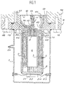
- the invention more specifically relates to a cryostat for cryogenic cooler using a closed working gas circuit between a compression located in a pressure oscillator housing associated and a relaxation room located at the bottom of the cryostat, in heat exchange situation with a component to be cooled, comprising inside an envelope thermal insulation, integral with a mounting base on said housing, a thermal regenerator interposed on the working gas circuit.
- This regenerator is in annular arrangement around an extending axial volume between a cold exchanger which is in thermal contact with the component to be cooled and makes the regenerator communicate with said axial volume at the bottom of the cryostat.
- the cryostat also has a gas distribution ring in said regenerator, at the head of the cryostat, from a conduit drilled through the base for connection to the chamber compression.
- the timing ring is formed by a central piece mounting through said base axially at its center. Said central part is mounted removably in said base, in particular by tight screwing.
- At least one channel is advantageously provided passage of gas under controlled flow between a tank gas buffer formed inside the oscillator housing pressure, and the internal axial volume of the cryostat which works in gas tube. It is also advantageous to add one or more other flow-controlled channels allowing hot gas to be drawn directly at the outlet compression, at the timing ring to the regenerator.
- the internal volume is at the contrary occupied by the displacer piston, which is preferably solid, made of a weak material thermal conductivity, and which leaves only the volume of the expansion chamber at the bottom of the cryostat.
- the central piece is made integral with a central tube limiting said axial volume.
- This tube is then advantageously of the same internal diameter as the axial bore of the model intended for connection of the cryostat to a cooler Stirling cycle. It can therefore constitute either the tube containing the pulsed gas in the first model, namely the guide tube of the cooler displacement piston in the second case.
- the cryostat is associated with the cryostat a hot exchanger, positioning in the internal volume at the top of the cryostat. Its role is located in the evacuation of calories which takes place by heat loss to the outside through the base and the casing of the compressor part of the cooler, made for this purpose of thermally conductive material. It is especially useful in the cooler variant with pulsed gas tube, taking into account the heat to be evacuated in gas tube outlet, which adds to the stored heat by the gas back from the regenerator.
- the invention foresees, according to a secondary characteristic, that one can apply advantageously with others in any operating combination, to use a geometry structure of revolution, alternating around the axis of the cryostat, in a daisy arrangement, massive areas in material good thermal conductor and void areas open to the passage of gas. As a result, these areas are in particular on horseback, on both sides, in relation to a centering shoulder at the end of the central tube.
- piloting means comprising a crankshaft actuating a transmission mechanism of movement by movable ball bearing in a groove formed transversely outside said piston.
- the arrangement ring of the regenerator lends itself particularly well to a manufacture from a sheet wound on itself.
- the invention makes it possible to significantly improve the efficiency of the heat exchanges sought, compared to stacks of conventional grids or balls, in using for this a sheet of suitable material, which has been previously machined, in particular by photolithographic process, so as to form longitudinal strips with smooth surfaces and transverse bars in extra thickness occasionally joining the strips successive.
- the different bands are succeed the length of the regenerator. They form annular smooth surface layers intersected by intervals between bands and bars inserted between the layers help to distribute the flow in all directions at each cross section level.
- the cryostat of the figure 1 is used in combination with a pressure oscillator either to constitute a cryogenic cooler of the pulsed gas according to Figure 6, or alternatively to constitute a Stirling cycle type cooler as shown in Figure 5.
- a pressure oscillator either to constitute a cryogenic cooler of the pulsed gas according to Figure 6, or alternatively to constitute a Stirling cycle type cooler as shown in Figure 5.
- the cooler thus constituted is of compact construction, the cryostat and pressure oscillator being integrated in one same mechanical assembly.
- cryostat is not limited, as in the embodiments known, to a thermal insulation envelope intended to receive a cold finger previously formed in all its functional organs necessary for the implementation work of the thermodynamic cycle of the working gas.
- the passive functional organs which are not subject to displacement during operation, are permanently installed in the cryostat, the latter being constructed so that it can be connected alternately at the user's choice, at the housing of an oscillator pressure either from a specific cooler for implementation of a Stirling cycle, ie of a cooler of the pulsed gas tube type.
- regenerator 5 with its own envelopes, including an outer envelope which is then separate from the inner wall 2 of the thermal insulation envelope and / or an internal envelope which is then added against the tube central 3.
- this exchanger 8 which constitutes in operation the cold exchanger of the cooler.
- this exchanger is designed and arranged to facilitate the transfer of cooling capacity resulting from the expansion of the work towards a component to be cooled 21, while ensuring pneumatic communication allowing the passage of gas of work between the bottom of the axial volume 6 and the space ring occupied by the regenerator 5.
- the intermediate shell of the cryostat of the invention constituted by the wall 2, is closed at its end lower, at the bottom of the cryostat, by a transverse plate 22 against which the cold exchanger 8 is affixed.
- the component 21 On its opposite side to this exchanger is mounted the component 21, generally by simple bonding.
- an electronic component 21 for example a optoelectronic detector
- an electrical distribution ring 23 of which the conductive parts pass through watertight bushings through the outer wall of the insulation jacket thermal 1, as well as conductive wires 24 which then connect to component 21.
- the envelope 1 as a whole has the function of limit heat losses by radiation or convection to level of organs involved in the thermodynamic cycle of the complete cooler in the cold zone thereof.
- a quality of stainless steel corresponding to a alloy with low thermal conductivity adapted to be compatible with the working gas used, which is preferably helium in the case of the regenerator at metallic foil rolled up as described below.
- the outer wall of the envelope 1 is produced also in stainless steel, or possibly in one appropriate quality of glass, for economic reasons.
- the base 4 At the head of the cryostat, at the upper end of the thermally insulating envelope 1 and of the regenerator 5, the base 4 is on the contrary in the hot zone of the cooler in operation, where there is also pressure working gas dynamics, subjected to pulsations of periodic pressures, printed by the moving parts of the cooler when the cryostat is connected to the housing 50 an associated pressure oscillator.
- the base 4 there is a collar circular 16, pierced with holes for the passage of screws 48 fixing to the casing 50 of the cooler, which is connected by pressing on the upper face of the flange 16, opposite the thermal envelope 1.
- a ring 17, forming part of the base 4 which ensures the centering of the two elements one inside the other.
- the tight connection of these two elements (cryostat and pressure oscillator) vis-à-vis the outside is ensured by a seal 19, housed in an annular groove on the face upper part of the collar 16.
- the base 4 delivers passage, in the axis of the system, to a central part 10, tightly screwed into the ring 17, which is internally threaded.
- a throat hexagonal 41 formed in its upper planar face, serves to handling during assembly.
- this central piece of the cryostat is designed in two different models which, by their external geometry, their dimensioning, and their functional design, are interchangeable in one same construction of cryostat. Both models are illustrated by FIG. 1 and by FIG. 2, depending on whether the cryostat 30 is mounted to be coupled with housings 50 or 60 from either of the two pressure oscillators in the two cooler variants shown on the Figures 6 and 5 respectively.
- this central part therefore in in particular that bearing the reference 10 in FIG. 1, here consists of a single piece with the inner tube 3 cryostat.
- this crown forms a distribution crown 71, for the annular distribution of the gas at the top of the regenerator 5. Consequently, this crown is placed above of it (in the vertical arrangement shown, cryostat under the casing 50), and more precisely at center of the base 4 in its main part formed by the flange 16.
- the crown of distribution 71 has a circular groove 45, hollowed out in its underside, which abuts the regenerator 5. This groove communicates through orifices 46 with an annular chamber 43, extended upwards at 42, which is arranged externally in the part of the room central 10 located at the flange 16, between this part and the face opposite the base 4.
- the central part 10 is shown in Figure 1 in the model suitable for a cooler TGP type illustrated in Figure 6.
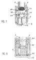
- the second model of central part of the cryostat, intended for a Stirling cycle cooler, is shown on the schematic representation in exploded layout of Figure 2.
- the central part 20 is identical to the previous one externally, but internally, it simply comprises an axial bore 72, formed all along through it, at the same diameter as the tube 3 of which it extends the central volume.
- the calibrated orifices of channels 11-12 are working, in a conventional manner in itself, like valves introducing pneumatic impedances.
- Main channel 11 as well equipped in operation provides the useful phase shift between the pressure wave generated by the pressure oscillator and the resulting flow variations in the container tube pulsed gas.
- Secondary impedance (channel 12) allows to bring a fraction of the periodic feed rate of the tube by taking it directly out of compression, by diversion of the circulation passing to through the regenerator and the tube. This decreases the load thermal on the regenerator and helps to improve the efficiency of the chiller, in the case of a gas cycle pulsed.
- FIG. 1 finally shows an exchanger 9, located at hot zone in the central volume, at the crown distribution 71.
- This hot exchanger can possibly be performed analogously to what will be described more far for the cold exchanger, the main thing being that in this variant embodiment of the cryostat of the invention, it complete the removal of excess calories from the thermodynamic cycle by completing, starting from the zone hot of the pulsed gas tube, heat losses outwardly occurring through the base 4, and incidentally from the associated pressure oscillator housing.
- the thermal regenerator 5 is advantageously constituted, as it appears from Figures 1 and 3, so to fully play its role of thermal accumulator for the recovery taking place, in a conventional manner, between the working gas passing from the compression phase to the expansion phase and the working gas passing from the expansion during the compression phase.
- regenerator comes in the form of a leaf continuous which is wound in a series of turns around the central tube 3 which limits the internal volume 6 of the regenerator, so as to fill, as completely as it is possible in industrial practice, the annular space between this tube 3, which forms its envelope ferrule internal, and its associated external envelope shell, constituted by the internal wall 2 of the insulating envelope 1.
- Machining processes by photolithography which are known in themselves, are particularly interesting in this sense, insofar as they represent means particularly simple to implement for a limited cost price, when it comes to driving to the configuration illustrated by the detail in FIG. 3.
- the sheet which is thus wound in contiguous consecutive turns forms a succession of separate longitudinal bands 27, which are oriented perpendicular to the axis of the cryostat and which are separated from each other by intervals 28.
- Bars 26 are formed in excess thickness of the strips and across them in a perpendicular direction. They are evenly distributed over the entire length and leaf height and staggered, each joining two successive bands over the interval that separates them.
- a regenerator thus constructed, we can cite as an example the case of a sheet 100 to 200 microns thick, hollowed out halfway through each side, for a regenerator from 2 to 3 millimeters in radial thickness.
- the tapes and intervals between them can, for example, be of a same width, of the order of 50 to 100 microns.
- the length transverse of the bars 26 can correspond, here again for example, at 1.5 times the repetition step of longitudinal strips 27, with a width of about half lesser and a distance between two successive bars offset, equivalent to about three times the width of each.
- the invention thus makes it possible to take advantage of a relationship between local convective exchange and losses of longitudinal loads which, in the case of plates parallel to the axis of the cold finger, would be greater than the value that can be obtained by the usual stacks of grids or balls, however that in this form of practical realization, it ensures better distribution of the gas flow between the parallel layers of smooth surfaces.
- barriers 26 which remain low dimensions compared to the length and thickness of the regenerative, also allows the introduction of an interrupt of the longitudinal flow between the strip layers successive from one end to the other of the regenerator, and thereby to stabilize the overall gas flow. Simultaneously, like these bars adjoin two adjacent layers of bands, we thanks to them a reduction in energy losses thermal by conduction in the longitudinal direction. Simultaneously, this ensures a reduction in energy losses thermal by conduction in the longitudinal direction.
- regenerator 5 allows, particularly advantageously in the context of the present invention to obtain a relationship between the exchange local convective and longitudinal pressure drop very advantageous, while improving the flow distribution of gas between the parallel layers oriented longitudinally, up to recovery performance thermal at least equivalent, if not greater than those that we know get in known achievements by regenerators with stacked transverse grids or balls.
- This cold exchanger is produced in accordance with this which emerges from Figures 1, 2 and 4, in a form called Daisy. It is constituted by a structure with geometry of revolution, which is made of a material strongly conductor such as copper or aluminum.
- This structure alternates in a star around a central core 31, empty areas 32 hollowed out through its longitudinal thickness and massive zones 33 ensuring the thermal conduction. Both extend radially astride the shoulder 34, in part and from the end of the central tube 3. They leave therefore the gas circulate freely between the central volume 6 of the cryostat (or at least the expansion chamber remaining at the bottom of the cryostat in the case of a cooler according to the figure 5 applying a Stirling cycle), bypassing the lower end of the central tube 3 received in shoulder 34.
- Such a miniature exchanger for example under 5 mm diameter and 3 mm thick, can be manufactured easily by electrochemical machining of a cylindrical bar, which is then cut into sections.
- the core 31 can also be pierced with a empty passage in its center, and there is no need to leave a peripheral crown of material, contiguous continuously with the central tube 3.
- FIG. 5 illustrates the combination of the cryostat of the previous figures, using the central part 20 of the Figure 2, with a pressure oscillator corresponding to the configuration of a Stirling cycle cooler, in which the piloting is with rotary motor.
- the displacement piston 55 is axially movable in the internal volume 6 of the cryostat 30. It occupies almost everything volume, leaving no room at the bottom of the tube 3 which constitutes his guide, that the thickness of the expansion chamber, considerably enlarged in the figure compared to the practical reality.
- Figure 6 uses an oscillator of pressure designed for a TGP type cooler including the casing 50 is connected to the cryostat around the central part 10 of the model in FIG. 1.
- the mode of piloting is of rotary type.
- the motor shaft is perpendicular to the axis of the system and, by an axis crankshaft off center 66, it involves an oscillating movement, a single piston 74.
- the piston 74 is movable, vertically on the figure, in the axis of the cryostat, in a jacket formed at inside the housing 50.
- the internal cage 68 On the offset axis 66 is mounted the internal cage 68 a ball bearing, the outer cage 67 of which is trapped in a rectilinear groove 75 dug laterally in the peripheral surface of the piston 74, perpendicular to its axis and to the plane of the figure. This provision ensures the reciprocating movement of the piston while immobilizing it in rotation.
- the compression chamber 63 is formed between the upper end face of the piston and the casing 60. It is connected, as in the previous case, by a hole 62 and a conduit 61 to channel 39 opening into the chamber distribution of the cryostat.
- the exchanger 8 here consists of lobes 77 of massive material in radiating arrangement around a core central 34. Between these lobes 77 are the passages of gases 78 which connect the lower end of the regenerator with the axial volume of the tube 3.
- the gas flow tranquilization laminate which has already been discussed, is represented by a stack of perforated grids 81 mounted in section transverse of the tube 3 at this lower end. These grids can be retained by legs of tube 3, as shown, or just stuck between the end of the tube and the exchanger 8 in its central part limited by a tube centering shoulder 79 3. In all cases, the gas passing between the exchanger lobes is found to have cross the stack of grids.
- This circulation is indicated by arrows in FIG. 8, which relates to another embodiment particularly advantageous especially since it facilitates a tranquilization of the gas flow as close as possible to the cold plate 22.
- the cold exchanger is produced there in two parts 83 and 84 concentrically embossed one in the other; Each has its own material lobes heat exchange alternating with empty areas free to gas circulation. In other words, functionally the exchanger is therefore pierced with channels dividing into two crowns, one under regenerator 5, the other at the end of the tube 3.
- the internal part 83 of the exchanger is shorter than the external part 84 which surrounds it and so that the end of the tube 3 comes center in the part 84 in abutment on the part 83.
- a stack of grids 82 constitutes the laminated to calm the gas flow. These grids are interposed directly against the cold plate 22 between this and the two parts 83 and 84 of the exchanger. In case if necessary, they could be blocked in the exchanger on the outskirts, providing for this purpose a shoulder in the part 84 forming the annular ring of this exchanger.
Landscapes
- Engineering & Computer Science (AREA)
- Physics & Mathematics (AREA)
- Mechanical Engineering (AREA)
- Thermal Sciences (AREA)
- General Engineering & Computer Science (AREA)
- Containers, Films, And Cooling For Superconductive Devices (AREA)
Claims (15)
- Kryostat für Tiefsttemperatur-Kühleinrichtung, der zwischen einer Verdichtungskammer, die sich in einem zugeordneten Druckoszillatorgehäuse befindet, und einer Entspannungskammer, die sich am Boden des Kryostaten befindet und mit einer zu kühlenden Komponente in Wärmeaustausch steht, einen geschlossenen Arbeitsgaskreis verwendet und innerhalb einer Wärmeisolierhülle (1), die mit einer Grundplatte (4) für die Anbringung am Gehäuse (50, 60) fest verbunden ist, einen in den Arbeitsgaskreis eingesetzten Wärmespeicher (5) umfaßt, der ringförmig um ein axiales Volumen (6) angeordnet ist, das sich zwischen einem Kältetauscher (8) erstreckt, der mit der zu kühlenden Komponente (21) in thermischem Kontakt steht und am Boden des Kryostaten (30) eine Verbindung zwischen dem Wärmespeicher (5) und dem axialen Volumen herstellt, dadurch gekennzeichnet, daß er einen Kranz (71) umfaßt, der im Wärmespeicher (5) am oberen Ende des Kryostaten Gas von einer durch die Grundplatte (4) verlaufenden Leitung (39), die eine Verbindung mit der Verdichtungskammer herstellt, verteilt, wobei der Verteilungskranz (71) durch ein Mittelteil (10, 20) gebildet ist, das über der Grundplatte (4) abnehmbar angebracht ist und axial durch deren Zentrum verläuft, und zwischen einem Modell, das geeignet ist für eine Kühleinrichtung des Typs mit pulsierendem Gas, in dem das axiale Volumen (6) als Gaskolben arbeitet, und einem Modell, das geeignet ist für eine Kühleinrichtung des Typs mit Stirling-Zyklus, in dem sich ein Verdrängerkolben in dem axialen Volumen verschiebt, austauschbar ist.
- Kryostat nach Anspruch 1, dadurch gekennzeichnet, daß das Mittelteil, das den Verteilungskranz (71) aufweist, mit einem das axiale Volumen (6) begrenzenden Rohr (3) einteilig verbunden ist.
- Kryostat nach einem der Ansprüche 1 oder 2, dadurch gekennzeichnet, daß das Mittelteil in dem für eine Kühleinrichtung des Typs mit Stirling-Zyklus geeigneten Modell eine axiale Bohrung aufweist, durch die ein Verdrängerkolben der Kühleinrichtung verlaufen kann, der in das axiale Volumen (6) dicht gleitend eingesetzt ist.
- Kryostat nach einem der Ansprüche 1 bis 3, dadurch gekennzeichnet, daß der Kältetauscher (8) eine Struktur mit rotationssymmetrischer Geometrie aufweist, in der sich um die Mittelachse des Kryostaten massive Zonen (33) aus einem gut wärmeleitenden Material und Leerzonen (32), die für den Gasdurchlaß offen sind, abwechseln.
- Kryostat nach Anspruch 4, dadurch gekennzeichnet, daß sich die Leerzonen (33) beiderseits einer Schulter (34) für die Zentrierung eines das axiale Volumen begrenzenden Mittelrohrs (3) erstrecken.
- Kryostat nach einem der Ansprüche 1 bis 5, dadurch gekennzeichnet, daß die Wärmeisolierhülle (1) eine an den Wärmespeicher angrenzende röhrenförmige Innenwand (2) aufweist, die durch eine Platte (22) für die Aufnahme der zu kühlenden Komponente verschlossen ist, an der der Kältetauscher (8) anliegt.
- Kryostat nach einem der Ansprüche 1 bis 6, dadurch gekennzeichnet, daß der Wärmespeicher aus einer aufgewickelten Folie in dem ringförmigen Raum zwischen einer Innenwand (2) der Hülle (1) und einem das axiale Volumen begrenzenden Mittelrohr (3) in der Verlängerung des Verteilungskranzes gebildet ist, wobei die Folie insbesondere durch ein photolithographisches Verfahren in der Weise bearbeitet ist, daß getrennte Stege (27) mit glatten Oberflächen parallel zur Mittelachse des Kryostaten und transversale, überdicke Spangen (26), die die aufeinanderfolgenden Stege punktförmig miteinander verbinden, ausgebildet sind.
- Kryostat nach einem der Ansprüche 1 bis 7, dadurch gekennzeichnet, daß der Verteilungskranz eine untere Fläche aufweist, mit der er am Wärmespeicher anliegt und in der eine kreisförmige Nut (45) ausgespart ist, die durch regelmäßig verteilte Öffnungen mit einer ringförmigen Kammer (42, 43) in Verbindung steht, die auf Höhe der Grundplatte (4) des Kryostaten außen um das Mittelteil ausgebildet ist und mit dem Kanal (39) in Verbindung steht.
- Kryostat nach einem der Ansprüche 1 bis 8, gekennzeichnet durch einen Verbund aus übereinander angeordneten Gasströmungs-Beruhigungsgittern, der am Boden des axialen Volumens gegenüber dem Kältetauscher angeordnet ist.
- Kryostat nach einem der Ansprüche 1 bis 9, dadurch gekennzeichnet, daß die Grundplatte (4) einen Ring (17) für die Anbringung des Mittelteils (10, 20) in der Verlängerung des axialen Volumens (6) bildet.
- Kühleinrichtung, dadurch gekennzeichnet, daß sie einen Kryostaten nach einem der Ansprüche 1 bis 10 enthält und, wenn sie dem für eine Kühleinrichtung mit Stirling-Zyklus geeignetem Modell entspricht, mit dem Gehäuse (60) eines Druckoszillators verbunden ist, der einen Verdrängerkolben umfaßt, der phasenverschoben zu einem Verdichtungskolben synchronisiert vorgesteuert wird, und daß der Verdrängerkolben (55) in dem inneren Volumen (6) des Kryostaten (30) axial beweglich ist und sich dicht gleitend in einer axialen Bohrung (72) bewegt, die hierzu in dem in der Grundplatte des Kryostaten angebrachten Mittelteil (20) vorgesehen ist.
- Kühleinrichtung, dadurch gekennzeichnet, daß sie einen Kryostaten nach einem der Ansprüche 1 bis 10 enthält und, wenn sie dem für eine Kühleinrichtung mit pulsierendem Gas geeignetem Modell entspricht, mit dem Gehäuse (50) eines Druckoszillators verbunden ist, das Mittel zur periodischen Vorsteuerung eines Gasverdichtungskolbens, der das Volumen der Verdichtungskammer verändert, und einen Pufferspeicher für Gas mit konstantem Druck umfaßt, und daß das in der Grundplatte (4) des Kryostaten angebrachte Mittelteil (10) Mittel für eine Druckluftverbindung mit gesteuertem Durchsatz mit dem Speicher (65) umfaßt.
- Kühleinrichtung nach Anspruch 12; dadurch gekennzeichnet, daß das Mittelteil zusätzlich zu einem Gasdurchlaßkanal (11) mit gesteuertem Durchsatz zwischen dem Pufferspeicher für Gas mit konstantem Druck, der in dem Gehäuse (50) des Druckoszillators ausgebildet ist, und dem inneren axialen Volumen (6) des Kryostaten, das sich im Betrieb mit Gas füllt, um einen Gaskolben mit Phasenverschiebung in bezug auf die periodische Verdichtung zu bilden, wenigstens einen weiteren Kanal (12) mit gesteuertem Durchsatz umfaßt, der in eine ringförmige Kammer (42, 43) mündet, die durch das gemäß Anspruch 8 verwirklichte Mittelteil gebildet ist.
- Kühleinrichtung nach Anspruch 12 oder 13, dadurch gekennzeichnet, daß das Gaspuffervolumen in einem Verdichtungskolben ausgebildet ist, der durch die Vorsteuermittel gesteuert wird und hierzu in einem Führungsmantel des Kolbens direkt in das Mittelteil (10) des Kryostaten mündet.
- Kühleinrichtung nach einem der Ansprüche 12 bis 14, dadurch gekennzeichnet, daß die Vorsteuermittel in einer Konfiguration des Typs mit rotierendem Motor eine Kurbelwelle enthalten, die einen Bewegungsübertragungsmechanismus über ein Kugellager betätigen, das in einer Nut, die transversal zur Außenseite des Kolbens ausgespart ist, beweglich ist.
Applications Claiming Priority (2)
| Application Number | Priority Date | Filing Date | Title |
|---|---|---|---|
| FR9605086 | 1996-04-23 | ||
| FR9605086A FR2747767B1 (fr) | 1996-04-23 | 1996-04-23 | Cryostat pour refroidisseur cryogenique et refroidisseurs comportant un tel cryostat |
Publications (2)
| Publication Number | Publication Date |
|---|---|
| EP0803687A1 EP0803687A1 (de) | 1997-10-29 |
| EP0803687B1 true EP0803687B1 (de) | 2002-06-26 |
Family
ID=9491490
Family Applications (1)
| Application Number | Title | Priority Date | Filing Date |
|---|---|---|---|
| EP19970400898 Expired - Lifetime EP0803687B1 (de) | 1996-04-23 | 1997-04-22 | Kryostat für Tiefsttemperatur-Kälteanlage und Kälteanlagen mit einem solchen Kryostat |
Country Status (3)
| Country | Link |
|---|---|
| EP (1) | EP0803687B1 (de) |
| DE (1) | DE69713547T2 (de) |
| FR (1) | FR2747767B1 (de) |
Families Citing this family (6)
| Publication number | Priority date | Publication date | Assignee | Title |
|---|---|---|---|---|
| JP3751175B2 (ja) * | 1999-12-21 | 2006-03-01 | シャープ株式会社 | スターリング冷凍機 |
| FR2815700B1 (fr) * | 2000-10-19 | 2004-10-22 | Sagem | Dispositif cryogenique a cycle ferme |
| KR100393792B1 (ko) * | 2001-02-17 | 2003-08-02 | 엘지전자 주식회사 | 맥동관 냉동기 |
| US8910486B2 (en) * | 2010-07-22 | 2014-12-16 | Flir Systems, Inc. | Expander for stirling engines and cryogenic coolers |
| GB2510912B (en) * | 2013-02-19 | 2018-09-26 | The Hymatic Engineering Company Ltd | A pulse tube refrigerator / cryocooler apparatus |
| CN118129389B (zh) * | 2024-05-07 | 2024-07-02 | 上海量羲技术有限公司 | 一种稀释制冷装置 |
Family Cites Families (12)
| Publication number | Priority date | Publication date | Assignee | Title |
|---|---|---|---|---|
| US3220201A (en) * | 1965-01-25 | 1965-11-30 | Little Inc A | Cryogenic refrigerator operating on the stirling cycle |
| US3851173A (en) * | 1973-06-25 | 1974-11-26 | Texas Instruments Inc | Thermal energy receiver |
| US4425764A (en) * | 1982-03-16 | 1984-01-17 | Kryovacs Scientific Corporation | Micro-cryogenic system with pseudo two stage cold finger, stationary regenerative material, and pre-cooling of the working fluid |
| US4550571A (en) * | 1983-12-28 | 1985-11-05 | Helix Technology Corporation | Balanced integral Stirling cryogenic refrigerator |
| US4569203A (en) * | 1984-10-29 | 1986-02-11 | Texas Instruments Incorporated | Cryogenic cooler |
| DE3812427A1 (de) * | 1988-04-14 | 1989-10-26 | Leybold Ag | Verfahren zur herstellung eines regenerators fuer eine tieftemperatur-kaeltemaschine und nach diesem verfahren hergestellter regenerator |
| US4858442A (en) * | 1988-04-29 | 1989-08-22 | Inframetrics, Incorporated | Miniature integral stirling cryocooler |
| US5293748A (en) * | 1990-07-10 | 1994-03-15 | Carrier Corporation | Piston cylinder arrangement for an integral Stirling cryocooler |
| US5435136A (en) * | 1991-10-15 | 1995-07-25 | Aisin Seiki Kabushiki Kaisha | Pulse tube heat engine |
| GB9213350D0 (en) * | 1992-06-24 | 1992-08-05 | Marconi Gec Ltd | Refrigerator |
| FR2702269B1 (fr) * | 1993-03-02 | 1995-04-07 | Cryotechnologies | Refroidisseur muni d'un doigt froid du type tube pulsé. |
| US5613365A (en) * | 1994-12-12 | 1997-03-25 | Hughes Electronics | Concentric pulse tube expander |
-
1996
- 1996-04-23 FR FR9605086A patent/FR2747767B1/fr not_active Expired - Fee Related
-
1997
- 1997-04-22 DE DE1997613547 patent/DE69713547T2/de not_active Expired - Lifetime
- 1997-04-22 EP EP19970400898 patent/EP0803687B1/de not_active Expired - Lifetime
Also Published As
| Publication number | Publication date |
|---|---|
| DE69713547D1 (de) | 2002-08-01 |
| DE69713547T2 (de) | 2003-01-16 |
| EP0803687A1 (de) | 1997-10-29 |
| FR2747767B1 (fr) | 1998-08-28 |
| FR2747767A1 (fr) | 1997-10-24 |
Similar Documents
| Publication | Publication Date | Title |
|---|---|---|
| EP0119502B1 (de) | Thermoelektrische Anlage | |
| EP2223022B1 (de) | Magnetokalorischer generator | |
| EP1969294A2 (de) | Vorrichtung zur kälte- und wärmeerzeugung durch einen magnetokalorischen effekt | |
| FR2505035A1 (fr) | Compresseur hermetique de refrigeration equipe d'un silencieux, notamment pour refrigerateurs menagers | |
| EP1581774A1 (de) | Verfahren und vorrichtung zur kontinuierlichen kälte-und wärmeerzeugung durch magneto-kalorischen effekt | |
| WO2010061064A1 (fr) | Generateur thermioue a materiau magnetocalorioue | |
| WO2010037980A1 (fr) | Structure d'echangeur thermique et chambre de compression ou de detente isotherme | |
| EP1040274A1 (de) | Verdrängungspumpe | |
| FR2942305A1 (fr) | Generateur thermique magnetocalorique | |
| EP0803687B1 (de) | Kryostat für Tiefsttemperatur-Kälteanlage und Kälteanlagen mit einem solchen Kryostat | |
| EP2480777A1 (de) | Thermodynamische maschine mit stirlingkreisprozess | |
| CA2595360A1 (fr) | Pompe a vide a cycle de translation circulaire a plusieurs arbres | |
| EP0114781B1 (de) | Wärmemaschine mit internem oder externem Energiebrunnen, mit Zylinder des Verdichtertyps oder Stirling-Zyklustyps | |
| EP2603747B1 (de) | Wärmegenerator mit magnetokalorischem material | |
| EP2399088A1 (de) | Magnetokalorischer wärmeerzeuger | |
| WO2020127300A1 (fr) | Regenerateur et procede de fabrication d'un tel regenerateur | |
| FR2821150A1 (fr) | Refregirateur a tube pulse | |
| FR2566886A1 (fr) | Refrigerateur cryogenique a soupape poussee par la force elastique d'un gaz | |
| FR2566887A1 (fr) | Refrigerateurs cryogeniques a etages multiples, capables d'obtenir une refrigeration a une temperature se situant entre 4,5 et 10o kelvin | |
| FR2741940A1 (fr) | Refroidisseur a moteur lineaire | |
| FR2742215A1 (fr) | Refroidisseur stirling a pilotage rotatif | |
| EP0258093B1 (de) | Joule-Thomson-Kühler und mit diesem Kühler versehener Kryostat | |
| FR3024768A1 (fr) | Machine thermique a materiau magnetocalorique du genre machine frigorifique ou pompe a chaleur | |
| FR2760075A1 (fr) | Systeme de conditionnement de composants fonctionnant a temperature cryogenique | |
| FR2754593A1 (fr) | Procede et dispositif de refroidissement cryogenique de composants par detente de joule-thomson |
Legal Events
| Date | Code | Title | Description |
|---|---|---|---|
| PUAI | Public reference made under article 153(3) epc to a published international application that has entered the european phase |
Free format text: ORIGINAL CODE: 0009012 |
|
| AK | Designated contracting states |
Kind code of ref document: A1 Designated state(s): DE FR GB NL |
|
| 17P | Request for examination filed |
Effective date: 19980417 |
|
| 17Q | First examination report despatched |
Effective date: 20001115 |
|
| GRAG | Despatch of communication of intention to grant |
Free format text: ORIGINAL CODE: EPIDOS AGRA |
|
| GRAG | Despatch of communication of intention to grant |
Free format text: ORIGINAL CODE: EPIDOS AGRA |
|
| GRAH | Despatch of communication of intention to grant a patent |
Free format text: ORIGINAL CODE: EPIDOS IGRA |
|
| RAP1 | Party data changed (applicant data changed or rights of an application transferred) |
Owner name: THALES CRYOGENIE S.A. |
|
| GRAH | Despatch of communication of intention to grant a patent |
Free format text: ORIGINAL CODE: EPIDOS IGRA |
|
| GRAA | (expected) grant |
Free format text: ORIGINAL CODE: 0009210 |
|
| AK | Designated contracting states |
Kind code of ref document: B1 Designated state(s): DE FR GB NL |
|
| REG | Reference to a national code |
Ref country code: GB Ref legal event code: FG4D Free format text: NOT ENGLISH |
|
| REF | Corresponds to: |
Ref document number: 69713547 Country of ref document: DE Date of ref document: 20020801 |
|
| GBT | Gb: translation of ep patent filed (gb section 77(6)(a)/1977) |
Effective date: 20020906 |
|
| PLBE | No opposition filed within time limit |
Free format text: ORIGINAL CODE: 0009261 |
|
| STAA | Information on the status of an ep patent application or granted ep patent |
Free format text: STATUS: NO OPPOSITION FILED WITHIN TIME LIMIT |
|
| 26N | No opposition filed |
Effective date: 20030327 |
|
| REG | Reference to a national code |
Ref country code: FR Ref legal event code: PLFP Year of fee payment: 20 |
|
| PGFP | Annual fee paid to national office [announced via postgrant information from national office to epo] |
Ref country code: FR Payment date: 20160323 Year of fee payment: 20 |
|
| PGFP | Annual fee paid to national office [announced via postgrant information from national office to epo] |
Ref country code: NL Payment date: 20160411 Year of fee payment: 20 |
|
| PGFP | Annual fee paid to national office [announced via postgrant information from national office to epo] |
Ref country code: DE Payment date: 20160419 Year of fee payment: 20 Ref country code: GB Payment date: 20160420 Year of fee payment: 20 |
|
| REG | Reference to a national code |
Ref country code: DE Ref legal event code: R071 Ref document number: 69713547 Country of ref document: DE |
|
| REG | Reference to a national code |
Ref country code: NL Ref legal event code: MK Effective date: 20170421 |
|
| REG | Reference to a national code |
Ref country code: GB Ref legal event code: PE20 Expiry date: 20170421 |
|
| PG25 | Lapsed in a contracting state [announced via postgrant information from national office to epo] |
Ref country code: GB Free format text: LAPSE BECAUSE OF EXPIRATION OF PROTECTION Effective date: 20170421 |