EP0803682B1 - Gasturbinenbrennkammer - Google Patents
Gasturbinenbrennkammer Download PDFInfo
- Publication number
- EP0803682B1 EP0803682B1 EP97301082A EP97301082A EP0803682B1 EP 0803682 B1 EP0803682 B1 EP 0803682B1 EP 97301082 A EP97301082 A EP 97301082A EP 97301082 A EP97301082 A EP 97301082A EP 0803682 B1 EP0803682 B1 EP 0803682B1
- Authority
- EP
- European Patent Office
- Prior art keywords
- combustor
- air
- fuel
- chamber
- combustion chamber
- Prior art date
- Legal status (The legal status is an assumption and is not a legal conclusion. Google has not performed a legal analysis and makes no representation as to the accuracy of the status listed.)
- Expired - Lifetime
Links
Images


Classifications
-
- F—MECHANICAL ENGINEERING; LIGHTING; HEATING; WEAPONS; BLASTING
- F23—COMBUSTION APPARATUS; COMBUSTION PROCESSES
- F23C—METHODS OR APPARATUS FOR COMBUSTION USING FLUID FUEL OR SOLID FUEL SUSPENDED IN A CARRIER GAS OR AIR
- F23C7/00—Combustion apparatus characterised by arrangements for air supply
- F23C7/02—Disposition of air supply not passing through burner
- F23C7/06—Disposition of air supply not passing through burner for heating the incoming air
-
- F—MECHANICAL ENGINEERING; LIGHTING; HEATING; WEAPONS; BLASTING
- F23—COMBUSTION APPARATUS; COMBUSTION PROCESSES
- F23C—METHODS OR APPARATUS FOR COMBUSTION USING FLUID FUEL OR SOLID FUEL SUSPENDED IN A CARRIER GAS OR AIR
- F23C6/00—Combustion apparatus characterised by the combination of two or more combustion chambers or combustion zones, e.g. for staged combustion
- F23C6/04—Combustion apparatus characterised by the combination of two or more combustion chambers or combustion zones, e.g. for staged combustion in series connection
- F23C6/045—Combustion apparatus characterised by the combination of two or more combustion chambers or combustion zones, e.g. for staged combustion in series connection with staged combustion in a single enclosure
- F23C6/047—Combustion apparatus characterised by the combination of two or more combustion chambers or combustion zones, e.g. for staged combustion in series connection with staged combustion in a single enclosure with fuel supply in stages
-
- F—MECHANICAL ENGINEERING; LIGHTING; HEATING; WEAPONS; BLASTING
- F23—COMBUSTION APPARATUS; COMBUSTION PROCESSES
- F23R—GENERATING COMBUSTION PRODUCTS OF HIGH PRESSURE OR HIGH VELOCITY, e.g. GAS-TURBINE COMBUSTION CHAMBERS
- F23R3/00—Continuous combustion chambers using liquid or gaseous fuel
- F23R3/28—Continuous combustion chambers using liquid or gaseous fuel characterised by the fuel supply
- F23R3/34—Feeding into different combustion zones
- F23R3/346—Feeding into different combustion zones for staged combustion
-
- F—MECHANICAL ENGINEERING; LIGHTING; HEATING; WEAPONS; BLASTING
- F23—COMBUSTION APPARATUS; COMBUSTION PROCESSES
- F23R—GENERATING COMBUSTION PRODUCTS OF HIGH PRESSURE OR HIGH VELOCITY, e.g. GAS-TURBINE COMBUSTION CHAMBERS
- F23R3/00—Continuous combustion chambers using liquid or gaseous fuel
- F23R3/28—Continuous combustion chambers using liquid or gaseous fuel characterised by the fuel supply
- F23R3/36—Supply of different fuels
Definitions
- This invention relates to a combustor for a gas - or liquid - fuelled turbine.
- a turbine engine typically includes an air compressor, at least one combustor and a turbine.
- the compressor supplies air under pressure to the combustor(s) - a proportion of the air is mixed with the fuel, while the remaining air supplied by the compressor is utilised to cool the hot surfaces of the combustor and/or the combustion gases, (ie. the gases produced by the combustion process, and/or other components of the turbine plant).
- lean burn combustors With the aim of reducing the amount of pollutants produced by the combustion process (particularly No x ), lean burn combustors have been proposed. Such combustors involve the premixing of air and fuel, with a relatively low proportion of fuel being utilised. Combustion then occurs at relatively low temperatures, which reduces the amount of pollutants produced.
- lean bum combustors have a narrow operating range, i.e. they cannot work satisfactorily with large variations in the quantity of fuel being supplied, and are susceptible to flame blow-out or flash-back.
- Stage combustors have, in the past, taken various designs, from those of fixed geometry which may have a number of burners and to which fuel is selectively directed depending on engine requirements, to those of a more complicated nature which may have movable parts to control the flow of combustion air.
- a specific example of a staged combustor is seen, for example, in EP 0 281 961 Al, which effects a first stage premix combustion process in a smaller head portion of the combustor and a second stage premix combustion process in a larger downstream portion of the combustor, the air for premixing with the fuel being suitably regulated for supply to either or both portions of the combustor.
- the present invention seeks to provide a three stage combustor of relatively simple construction but which is nonetheless effective in minimising the production of pollutants resulting from the combustion process and, in addition, operates with good combustion stability and an excellent turndown ratio whilst at the same time giving flashback - free combustion.
- a combustor for a gas turbine engine comprising:
- the combustion chamber and the pre-chamber are preferably defined by one or more cylindrical walls whereby the pre-chamber and the combustion chamber are each of cylindrical form.
- an increase in cross-sectional area comprises a transition region between the pre-chamber and the combustion chamber.
- the arrangement for introducing fuel into the elongated passage means may comprise a spray bar.
- the elongated passage means may be of generally annular form having a radially inner wall and a radially outer wall, the radially inner wall being constituted at least partly by a wall defining the combustion chamber, and said elongated passage means and said passage for cooling air may both be of annular form with the passage for cooling air being situated radially outside the combustor chamber and the elongated passage means being situated radially outside the passage for cooling air.
- the axial direction of flow of air or fuel/air mixture in the elongated passage means may be counter to the axial direction of flow of cooling air in the passage.
- the flow of fuel/air mixture in the elongated passage means may be in the same direction as the flow of cooling air in the cooling air passage means.
- the passage means may include turbulence inducing means, which may comprise at least one tube extending between the walls defining the passage means.
- the or each tube may be open-ended and provide means for entry of cooling air from outside the combustor to the passage for cooling air.
- the interior of the wall or walls defining the combustion chamber and the pre-chamber may have a thermal barrier coating applied thereto.
- At least one of the walls defining the elongated passage means may be of corrugated section.
- the first injection means provides an air/fuel mixture with local fuel rich areas.
- the second injection means may comprise a fuel spray bar, an air inlet means, and a chamber in which mixing of the fuel and air takes place.
- coolant air will pass from the cooling air passage means into the interior of the combustor; at least a part of the coolant air may pass into the combustion chamber through at least one orifice adjacent the downstream region thereof, and/or at least a part of the coolant air may pass into the interior of the combustor through at least one orifice in a transition duct region.
- the combustor may be embodied in any conventional turbine layout eg tubular (single-can or multi-can), turboannular or annular.
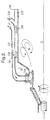
- the combustor 10 as illustrated in Figure 1 is of generally circular cylindrical form with a central longitudinal axis marked by line "A" and as indicated above the combustor 10 may, for example, constitute one of a plurality of such combustors arranged in an annular array.
- the combustor has a pre-chamber 11 and a main combustion chamber 12.
- the diameter of the major part of the main combustion chamber 12 is substantially greater than that of the pre chamber 11 with the transition region 100 between the chamber 11 and the chamber 12 being defined by a wall 101 of the combustor diverging in the downstream direction.
- a first injection means 13 which is located co-axially of axis A.
- the injection means 13 is provided with a supply of fuel (or a supply of fuel and air) as represented by the arrow 14, which supply is discharged into the pre-chamber 11.
- the fuel may be gas or liquid.
- the injection means 13 which may be of dual fuel type provides a fuel/air mixture in the pre-chamber 11 which, although of overall lean constitution, nevertheless has local fuel-rich areas. This is achieved by the injection means 13 incorporating or having associated therewith appropriate mixing means.
- the injection means 13 may incorporate a swirl means to give the mixture the appropriate degree of mixing as delineated above - such swirl means may involve vanes and/or suitably angling of passage(s) through the means. If fuel alone is injected into the pre-chamber 11 by the injection means 13 then some means will be provided whereby air in the pre-chamber (see later) is mixed with the fuel to give the appropriate form of mixture.
- the injection means 13 as diagrammatically represented comprises a circular cylindrical member formed with a plurality of passages therethrough.
- a central passage 15 acts to supply fuel to pre-chamber 11 whilst an annular array of passages 16 supply (swirled) air to mix with the fuel in pre-chamber 11.
- injection means 13 acts as a first stage injection means or burner being supplied with fuel 14 (or fuel/air) for engine starting and being the only fuel source up to an engine load of approximately 25%. Because the otherwise lean mixture has local fuel rich areas, flame stability in the pre-chamber 11 is assured at these low power settings.
- a second stage injection means 17 Mounted to extend generally radially outwardly from injection means 13 is a second stage injection means 17.
- the second stage injection means 17 may extend orthogonally of injection means 13 or at an angle thereto.
- the injection means 17 is designed as one of four mounted on the interior surface of an annular or frusto-conical wall extending from injection means 13.
- Each injection means 17 comprises a fuel spray bar 18, with a respective air inlet slot 19 extending therealongside: a respective mixing chamber 21 and a respective air/fuel outlet slot 20 are associated with the spray bar 18 and air inlet slot 19.
- the spray bar 18 and slots 19, 20 the fuel and air are caused to contrarotate in chamber 21 to give a mixture which is largely but not fully uniform in its air to fuel distribution.
- the injection means 17 thereby acts as a partial premix device.
- the direction of mixture issuing from the outlet slot 20 is arranged to be such that thorough mixing with the mixture supplied by the first injection means 13 is obtained but it must also be arranged that the velocity of the combined mixture is not reduced to the extent that flash-back might occur.
- the second injection means 17 is operated to supply fuel for combustion between approximately 25% and 75% of engine local, which fuel is added to that which has already been supplied by the first injection means 13. From approximately 75% to 100% engine load the fuel for combustion already supplied by the first injection means 13 and the second injection means 17 is supplemented by fuel supplied by a third injection means 30.
- the third injection means 30 is arranged to deliver fuel/air mixture into the upstream region of the main combustion chamber 12 optionally via the transition region 100, such fuel/air mixture being fully pre-mixed, ie, the fuel and air are substantially evenly distributed.
- the third injection means 30 comprises an elongated passage 31 with an inlet 32 for air and including a fuel spray bar 33, the air and fuel mixing as they pass along the passage as indicated by arrows 34 in an axial direction counter to the axial direction of flow of gases in the combustion chamber 12.
- the passage 31 is formed radially outside the main combustion chamber 12.
- the passage may be of annular form totally surrounding the combustion chamber 12 or there may be one or more separate cylindrical passages 31 running alongside the combustion chamber 12.
- the passage 31 is of annular form being formed between an annular sleeve 35 and the outer wall 36 of an annular passage 37 for cooling air surrounding the combustion chamber 12 and to be described in detail later.
- the passage 31 is relatively long which assists mixing of the air and fuel but in addition it may incorporate further means for creating turbulence to assist the mixing process.
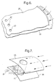
- turbulence creating means may comprise vanes but, as shown, it comprises one or more open-ended tubes 40 extending across annular passage 31 between walls 35, 36. Not only do these tubes 40 promote turbulence but they also act as entry conduits for cooling air.
- Figures 6, 7 show details of the form and positioning of these tubes and arrows 41 indicate the swirling motion of the fuel air mixture as promoted by tube 40.
- the walls 35, 36 are curved radially inwardly through a right angle as indicated at 50 so that the passage 31 is continued radially inwardly; this part of the passage includes one or more swirlers 51 immediately upstream of an outlet 52 which is arranged such that it directs the fully mixed air/fuel mixture axially into the combustion chamber 12 (optionally via transition region 100) at its upstream end. Once again, it has to be arranged that the mixture issuing from outlet 52 has a velocity sufficient to prevent flash-back.
- the combustor involves cooling arrangements utilising cooling air.
- the cooling air is supplied by the compressor of the gas turbine plant, with a certain percentage of air being supplied for combustion purposes and the remainder for cooling.
- the flow of cooling air in the illustrated embodiment is indicated by arrows 61.
- the combustion chamber is, in this embodiment, formed with a double wall whereof the radially outer wall 36 also constitutes the inner wall of the supply passage 31 and the radially inner wall 38 of passage 37 constitutes the axially extending wall of the combustion chamber 12.
- the cooling air enters passage 37 via the open-ended tubes 40 and enters the combustion chamber 12 via orifices 62 in wall 38.
- the wall 38 and its continuation 101 which is attached to or integral with wall 38, have a thermal barrier coating 63 on their interior surfaces as marked by dash lines.
- This barrier coating 63 restricts the heat passing through to the walls 38, 101 from where it is removed by the cooling air flow 61 flowing in passage 37 whereby the metal, of which walls 38, 101 are made, operates within its temperature limit.
- the spent and now heated cooling air enters the combustion chamber 12 (see arrow 63) in a dilution zone 70 downstream of the main combustion zone 71.
- the inner wall of passage 31 will be constituted by the single wall 38 of the combustor, and heat will be transferred straight from the combustion chamber 12 to the air/fuel mixture in passage 31.
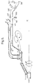
- FIG. 2 differs from Figure 1 inasmuch as the cooling air flow represented by arrows 261 enters passage 237 through an inlet 232 adjacent the downstream end of the combustor 210 and flows towards the upstream end of combustion chamber 12 where it enters the combustion chamber via a swirler 224.
- the coolant air in passage 237 flows in the same axial direction as the fuel/air mixture represented by arrows 234 flowing in passage 231. This means that there will be less heat transfer into the mixture 234, than in the arrangement of Figure 1, and less chance of ignition in passage 231.
- cooling air enters passage 337 through open-ended tubes 340. Some of this air flows through passage 337 to enter the combustion chamber 12 at the downstream end thereof while the rest of the air flows into the upstream end of the combustor chamber 12 through a swirler 324.
- Figure 4 is generally similar to that of Figure 1 save that the dilution air enters a combustor/turbine transition duct region 480 downstream of the main combustion chamber 12. This may result in better temperature profiling of the combustion gases in certain circumstances.
- the cooling air represented by arrows 561 enters the annular passage 537 through impingement holes 590 provided in the transition duct region 580 and flows into the combustion chamber 12 through orifices 562 to dilute the combustion gases and is also directed into the upstream end of the chamber 12 through orifices 591.
Landscapes
- Engineering & Computer Science (AREA)
- Chemical & Material Sciences (AREA)
- Combustion & Propulsion (AREA)
- Mechanical Engineering (AREA)
- General Engineering & Computer Science (AREA)
- Physics & Mathematics (AREA)
- Thermal Sciences (AREA)
- Gas Burners (AREA)
Claims (19)
- Vergasungsbrenner (10) für einen Gasturbinenmotor, aufweisendwobei der Vergasungsbrenner dadurch gekennzeichnet ist, daßeine Vorkammer (11),eine Hauptverbrennungskammer (12), die in Fließanordnung mit der Vorkammer angeordnet ist, wobei der Querschnittsbereich der Hauptverbrennungskammer größer als der Querschnittsbereich der Vorkammer ist und die Vorkammer direkt in die Hauptkammer führt, Durchlaßeinrichtungen (37) für Kühlluft in direkter Wärmeaustauschbeziehung mit der Hauptverbrennungskammer über zumindest einen Teil der Länge der Hauptverbrennungskammer, wobei ein Wandbereich (38) der Durchlaßeinrichtungen für die Kühlluft einen Wandbereich der Hauptverbrennungskammer enthalten,erste Einspritzeinrichtungen (13) zur Zuführung von Brennstoff oder einem Brennstoff-/Luft-Gemisch in die Vorkammer (11),zweite Einspritzeinrichtungen (17) zur Zuführung von Luft oder einem Brennstoff-/Luft-Gemisch in die Vorkammer,dritte Einspritzeinrichtungen (30) zur Zuführung von Luft oder einem Brennstoff-/Luft-Gemisch in die Hauptverbrennungskammer (12), wobei die dritten Einspritzeinrichtungen zumindest eine längliche Durchlaßeinrichtung (31) und eine Anordnung zur Einführung von Brennstoff in die längliche Durchlaßeinrichtung enthalten,
ein Wandbereich (36) der Durchlaßeinrichtung (37) für die Kühlluft einen Wandbereich der länglichen Durchlaßeinrichtung enthält, wobei die längliche Durchlaßeinrichtung (31) einen Wärmeaustauschbereich in direkter Wärmeaustauschbeziehung mit der Durchlaßeinrichtung für die Kühlluft enthält, um die Luft oder das Brennstoff-/Luft-Gemisch aufzuheizen, bevor sie/es in die Hauptverbrennungskammer eingeleitet wird. - Vergasungsbrenner nach Anspruch 1,
dadurch gekennzeichnet, daß die Verbrennungskammer (12) und die Vorkammer (11) von einer oder mehreren zylindrischen Wänden (38) begrenzt sind, wobei die Vorkammer (11) und die Verbrennungskammer (12) jeweils eine zylindrische Form aufweisen. - Vergasungsbrenner nach Anspruch 1 oder Anspruch 2,
dadurch gekennzeichnet, daß ein Anstieg im Querschnittsbereich einen Übergangsbereich (100) zwischen der Vorkammer (11) und der Verbrennungskammer (12) enthält. - Vergasungsbrenner nach einem der vorhergehenden Ansprüche,
dadurch gekennzeichnet, daß diese Anordnung zum Einführen von Brennstoff in die längliche Durchlaßeinrichtung (31) einen Sprühstab (33) enhält. - Vergasungsbrenner nach einem der Ansprüche 1 bis 4,
dadurch gekennzeichnet, daß die längliche Durchlaßeinrichtung (31) eine allgemeine ringförmige Form mit einer radial inneren Wand (36) und einer radial äußeren Wand (35) hat, wobei die radial innere Wand (36) zumindest teilweise aus einer Wand besteht, die die Verbrennungskammer (12) begrenzt. - Vergasungsbrenner nach Anspruch 5,
dadurch gekennzeichnet, daß die längliche Durchlaßeinrichtung (31) und der Durchlaß (37) für die Kühlluft beide eine ringförmige Form haben, wobei der Durchlaß (37) für die Kühlluft radial außerhalb der Verbrennungskammer (12) angeordnet ist und die länglichen Durchlaßeinrichtungen (31) radial außerhalb des Durchlasses (37) für die Kühlluft angeordnet sind. - Vergasungsbrenner nach einem der vorhergehenden Ansprüche,
dadurch gekennzeichnet, daß die Flußrichtung der Luft oder des Brennstoffs/Luft-Gemisches in der länglichen Durchlaßeinrichtung (31) entgegengesetzt zur Flußrichtung der Kühlluft in der Durchlaßeinrichtung (37) für die Kühlluft ist. - Vergasungsbrenner nach einem der Ansprüche 1 bis 6,
dadurch gekennzeichnet, daß der Strom des Brennstoff-/Luft-Gemisches in der länglichen Durchlaßeinrichtung (231) die gleiche Richtung hat wie der Strom der Kühlluft in der Durchlaßeinrichtung (237) für die Kühlluft. - Vergasungsbrenner nach einem der vorhergehenden Ansprüche,
dadurch gekennzeichnet, daß die Durchlaßeinrichtung (31) eine Turbulenzen erzeugende Einrichtung (40) enthält. - Vergasungsbrenner nach Anspruch 9,
dadurch gekennzeichnet, daß die Turzbulenzen erzeugende Einrichtung zumindestens ein Rohr (40) enthält, das sich zwischen den Wänden, die die Durchlaßeinrichtung (31) begrenzen, erstreckt. - Vergasungsbrenner nach Anspruch 10,
dadurch gekennzeichnet, daß das oder jedes Rohr ein offenes Endes aufweist und Einrichtungen zum Einlaß von Kühlluft von außerhalb des Brenners (10) in den Durchlaß (37) für die Kühlluft aufweisen. - Vergasungsbrenner nach einem der vorhergehenden Ansprüche,
dadurch gekennzeichnet, daß das Innere der Wand oder der Wände, die die Verbrennungskammer (12) und die Vorkammer (11) begrenzen, eine thermische Sperrschicht (63) aufweisen, die auf diese aufgebracht ist. - Vergasungsbrenner nach einem der vorhergehenden Ansprüche,
dadurch gekennzeichnet, daß zumindest eine der Wände, die die längliche Durchlaßeinrichtung (31) begrenzen, im Querschnitt geriffelt ist. - Vergasungsbrenner nach einem der vorhergehenden Ansprüche,
dadurch gekennzeichnet, daß die erste Einspritzeinrichtung (13) ein Luft/Brennstoff-Gemisch mit lokalen brennstoffreichen Bereichen aufweist. - Vergasungsbrenner nach einem vorhergehenden Ansprüche,
dadurch gekennzeichnet, daß die zweite Einspritzeinrichtung (17) einen Brennstoffnebelstab (18), eine Lufteinlaßeinrichtung (19) und eine Kammer (21) aufweist, in der eine Vermischung von Brennstoff und Luft stattfindet. - Vergasungsbrenner nach einem der vorhergehenden Ansprüche,
dadurch gekennzeichnet, daß die Kühlluft aus der Durchlaßeinrichtung (37) für die Kühlluft austritt und infolgedessen in das Innere der Verbrennungskammer (10) tritt. - Vergasungsbrenner nach Anspruch 16,
dadurch gekennzeichnet, daß ein Teil der Kühlluft durch zumindest eine Öffnung neben dem stromabwärts angeordneten Bereich in die Verbrennungskammer (12) tritt. - Vergasungsbrenner nach Anspruch 16 oder Anspruch 17,
dadurch gekennzeichnt,
daß zumindest ein Teil der Kühlluft durch zumindest eine Öffnung (562) in einem Übergangsleitungsbereich (480,580) in das Innere des Vergasungsbrenners tritt. - Vergasungsbrenner nach einem der Ansprüche 16 bis 19,
dadurch gekennzeichnet, daß zumindest ein Teil der Kühlluft über zumindest eine Öffnung (62) in einen stromaufwärts angeordneten Bereich der Verbrennungskammer (12) tritt.
Applications Claiming Priority (2)
| Application Number | Priority Date | Filing Date | Title |
|---|---|---|---|
| GB9606628A GB2311596B (en) | 1996-03-29 | 1996-03-29 | Combustor for gas - or liquid - fuelled turbine |
| GB9606628 | 1996-03-29 |
Publications (3)
| Publication Number | Publication Date |
|---|---|
| EP0803682A2 EP0803682A2 (de) | 1997-10-29 |
| EP0803682A3 EP0803682A3 (de) | 1999-11-03 |
| EP0803682B1 true EP0803682B1 (de) | 2003-09-03 |
Family
ID=10791258
Family Applications (1)
| Application Number | Title | Priority Date | Filing Date |
|---|---|---|---|
| EP97301082A Expired - Lifetime EP0803682B1 (de) | 1996-03-29 | 1997-02-20 | Gasturbinenbrennkammer |
Country Status (4)
| Country | Link |
|---|---|
| US (1) | US6209325B1 (de) |
| EP (1) | EP0803682B1 (de) |
| DE (1) | DE69724502T2 (de) |
| GB (1) | GB2311596B (de) |
Families Citing this family (109)
| Publication number | Priority date | Publication date | Assignee | Title |
|---|---|---|---|---|
| DE10035676A1 (de) * | 2000-07-21 | 2002-02-07 | Siemens Ag | Gasturbine und Verfahren zum Betrieb einer Gasturbine |
| US7047722B2 (en) * | 2002-10-02 | 2006-05-23 | Claudio Filippone | Small scale hybrid engine (SSHE) utilizing fossil fuels |
| US7117676B2 (en) * | 2003-03-26 | 2006-10-10 | United Technologies Corporation | Apparatus for mixing fluids |
| US7007486B2 (en) * | 2003-03-26 | 2006-03-07 | The Boeing Company | Apparatus and method for selecting a flow mixture |
| US6935116B2 (en) * | 2003-04-28 | 2005-08-30 | Power Systems Mfg., Llc | Flamesheet combustor |
| US6986254B2 (en) * | 2003-05-14 | 2006-01-17 | Power Systems Mfg, Llc | Method of operating a flamesheet combustor |
| US7043921B2 (en) * | 2003-08-26 | 2006-05-16 | Honeywell International, Inc. | Tube cooled combustor |
| US7127899B2 (en) * | 2004-02-26 | 2006-10-31 | United Technologies Corporation | Non-swirl dry low NOx (DLN) combustor |
| US7237384B2 (en) * | 2005-01-26 | 2007-07-03 | Peter Stuttaford | Counter swirl shear mixer |
| US20070028595A1 (en) * | 2005-07-25 | 2007-02-08 | Mongia Hukam C | High pressure gas turbine engine having reduced emissions |
| US20100018211A1 (en) * | 2008-07-23 | 2010-01-28 | General Electric Company | Gas turbine transition piece having dilution holes |
| DE102006042124B4 (de) * | 2006-09-07 | 2010-04-22 | Man Turbo Ag | Gasturbinenbrennkammer |
| EP2023041A1 (de) * | 2007-07-27 | 2009-02-11 | Siemens Aktiengesellschaft | Vormischbrenner und Verfahren zum Betrieb eines Vormischbrenners |
| EP2276559A4 (de) * | 2008-03-28 | 2017-10-18 | Exxonmobil Upstream Research Company | Systeme und verfahren zur emissionsarmen stromerzeugung und kohlenwasserstoffrückgewinnung |
| AU2009228283B2 (en) | 2008-03-28 | 2015-02-05 | Exxonmobil Upstream Research Company | Low emission power generation and hydrocarbon recovery systems and methods |
| WO2011059567A1 (en) | 2009-11-12 | 2011-05-19 | Exxonmobil Upstream Research Company | Low emission power generation and hydrocarbon recovery systems and methods |
| EP2107312A1 (de) * | 2008-04-01 | 2009-10-07 | Siemens Aktiengesellschaft | Pilotverbrennkammer in einem Brenner |
| EP2107311A1 (de) * | 2008-04-01 | 2009-10-07 | Siemens Aktiengesellschaft | Größenskalierung eines Brenners |
| EP2107313A1 (de) * | 2008-04-01 | 2009-10-07 | Siemens Aktiengesellschaft | Gestufte Brennstoffversorgung in einem Brenner |
| US8122700B2 (en) * | 2008-04-28 | 2012-02-28 | United Technologies Corp. | Premix nozzles and gas turbine engine systems involving such nozzles |
| US8176739B2 (en) * | 2008-07-17 | 2012-05-15 | General Electric Company | Coanda injection system for axially staged low emission combustors |
| AU2009303735B2 (en) | 2008-10-14 | 2014-06-26 | Exxonmobil Upstream Research Company | Methods and systems for controlling the products of combustion |
| US8161750B2 (en) * | 2009-01-16 | 2012-04-24 | General Electric Company | Fuel nozzle for a turbomachine |
| US7712314B1 (en) | 2009-01-21 | 2010-05-11 | Gas Turbine Efficiency Sweden Ab | Venturi cooling system |
| US8894363B2 (en) | 2011-02-09 | 2014-11-25 | Siemens Energy, Inc. | Cooling module design and method for cooling components of a gas turbine system |
| US8959886B2 (en) * | 2010-07-08 | 2015-02-24 | Siemens Energy, Inc. | Mesh cooled conduit for conveying combustion gases |
| BR112012031505A2 (pt) | 2010-07-02 | 2016-11-01 | Exxonmobil Upstream Res Co | combustão estequiométrica de ar enriquecido com recirculação de gás de exaustão |
| CN105863844B (zh) | 2010-07-02 | 2017-11-14 | 埃克森美孚上游研究公司 | 低排放动力产生系统和方法 |
| TWI564475B (zh) | 2010-07-02 | 2017-01-01 | 艾克頌美孚上游研究公司 | 低排放之三循環動力產生系統和方法 |
| EP2588727B1 (de) | 2010-07-02 | 2018-12-12 | Exxonmobil Upstream Research Company | Stöchiometrische verbrennung mit abgasrückführung und einem direktkontaktkühler |
| US9121279B2 (en) * | 2010-10-08 | 2015-09-01 | Alstom Technology Ltd | Tunable transition duct side seals in a gas turbine engine |
| TWI563165B (en) | 2011-03-22 | 2016-12-21 | Exxonmobil Upstream Res Co | Power generation system and method for generating power |
| TWI563166B (en) | 2011-03-22 | 2016-12-21 | Exxonmobil Upstream Res Co | Integrated generation systems and methods for generating power |
| TWI593872B (zh) | 2011-03-22 | 2017-08-01 | 艾克頌美孚上游研究公司 | 整合系統及產生動力之方法 |
| TWI564474B (zh) | 2011-03-22 | 2017-01-01 | 艾克頌美孚上游研究公司 | 於渦輪系統中控制化學計量燃燒的整合系統和使用彼之產生動力的方法 |
| US8281596B1 (en) * | 2011-05-16 | 2012-10-09 | General Electric Company | Combustor assembly for a turbomachine |
| US20120304652A1 (en) * | 2011-05-31 | 2012-12-06 | General Electric Company | Injector apparatus |
| CN103635750B (zh) | 2011-06-28 | 2015-11-25 | 通用电气公司 | 合理的延迟贫喷射 |
| US9267687B2 (en) | 2011-11-04 | 2016-02-23 | General Electric Company | Combustion system having a venturi for reducing wakes in an airflow |
| US8899975B2 (en) | 2011-11-04 | 2014-12-02 | General Electric Company | Combustor having wake air injection |
| US9810050B2 (en) | 2011-12-20 | 2017-11-07 | Exxonmobil Upstream Research Company | Enhanced coal-bed methane production |
| US9140455B2 (en) * | 2012-01-04 | 2015-09-22 | General Electric Company | Flowsleeve of a turbomachine component |
| US9170024B2 (en) | 2012-01-06 | 2015-10-27 | General Electric Company | System and method for supplying a working fluid to a combustor |
| US9353682B2 (en) | 2012-04-12 | 2016-05-31 | General Electric Company | Methods, systems and apparatus relating to combustion turbine power plants with exhaust gas recirculation |
| US9784185B2 (en) | 2012-04-26 | 2017-10-10 | General Electric Company | System and method for cooling a gas turbine with an exhaust gas provided by the gas turbine |
| US10273880B2 (en) | 2012-04-26 | 2019-04-30 | General Electric Company | System and method of recirculating exhaust gas for use in a plurality of flow paths in a gas turbine engine |
| US9328923B2 (en) * | 2012-10-10 | 2016-05-03 | General Electric Company | System and method for separating fluids |
| US9631815B2 (en) * | 2012-12-28 | 2017-04-25 | General Electric Company | System and method for a turbine combustor |
| US9574496B2 (en) | 2012-12-28 | 2017-02-21 | General Electric Company | System and method for a turbine combustor |
| US10100741B2 (en) | 2012-11-02 | 2018-10-16 | General Electric Company | System and method for diffusion combustion with oxidant-diluent mixing in a stoichiometric exhaust gas recirculation gas turbine system |
| US9803865B2 (en) | 2012-12-28 | 2017-10-31 | General Electric Company | System and method for a turbine combustor |
| US10215412B2 (en) | 2012-11-02 | 2019-02-26 | General Electric Company | System and method for load control with diffusion combustion in a stoichiometric exhaust gas recirculation gas turbine system |
| US9611756B2 (en) | 2012-11-02 | 2017-04-04 | General Electric Company | System and method for protecting components in a gas turbine engine with exhaust gas recirculation |
| US9599070B2 (en) | 2012-11-02 | 2017-03-21 | General Electric Company | System and method for oxidant compression in a stoichiometric exhaust gas recirculation gas turbine system |
| US9708977B2 (en) | 2012-12-28 | 2017-07-18 | General Electric Company | System and method for reheat in gas turbine with exhaust gas recirculation |
| US10107495B2 (en) | 2012-11-02 | 2018-10-23 | General Electric Company | Gas turbine combustor control system for stoichiometric combustion in the presence of a diluent |
| US9869279B2 (en) * | 2012-11-02 | 2018-01-16 | General Electric Company | System and method for a multi-wall turbine combustor |
| US10208677B2 (en) | 2012-12-31 | 2019-02-19 | General Electric Company | Gas turbine load control system |
| US9581081B2 (en) | 2013-01-13 | 2017-02-28 | General Electric Company | System and method for protecting components in a gas turbine engine with exhaust gas recirculation |
| JP6038674B2 (ja) * | 2013-02-04 | 2016-12-07 | 株式会社東芝 | ガスタービン燃焼器およびガスタービン |
| US9512759B2 (en) | 2013-02-06 | 2016-12-06 | General Electric Company | System and method for catalyst heat utilization for gas turbine with exhaust gas recirculation |
| TW201502356A (zh) | 2013-02-21 | 2015-01-16 | Exxonmobil Upstream Res Co | 氣渦輪機排氣中氧之減少 |
| US9938861B2 (en) | 2013-02-21 | 2018-04-10 | Exxonmobil Upstream Research Company | Fuel combusting method |
| US10221762B2 (en) * | 2013-02-28 | 2019-03-05 | General Electric Company | System and method for a turbine combustor |
| US20140250945A1 (en) | 2013-03-08 | 2014-09-11 | Richard A. Huntington | Carbon Dioxide Recovery |
| TW201500635A (zh) | 2013-03-08 | 2015-01-01 | Exxonmobil Upstream Res Co | 處理廢氣以供用於提高油回收 |
| EP2964735A1 (de) | 2013-03-08 | 2016-01-13 | Exxonmobil Upstream Research Company | Energieerzeugung und rückgewinnung von methan aus methanhydraten |
| US9618261B2 (en) | 2013-03-08 | 2017-04-11 | Exxonmobil Upstream Research Company | Power generation and LNG production |
| US9958161B2 (en) * | 2013-03-12 | 2018-05-01 | Pratt & Whitney Canada Corp. | Combustor for gas turbine engine |
| US9127843B2 (en) | 2013-03-12 | 2015-09-08 | Pratt & Whitney Canada Corp. | Combustor for gas turbine engine |
| US9228747B2 (en) | 2013-03-12 | 2016-01-05 | Pratt & Whitney Canada Corp. | Combustor for gas turbine engine |
| US9541292B2 (en) | 2013-03-12 | 2017-01-10 | Pratt & Whitney Canada Corp. | Combustor for gas turbine engine |
| CA2902809C (en) | 2013-03-13 | 2018-01-23 | Industrial Turbine Company (Uk) Limited | Lean azimuthal flame combustor |
| US9322553B2 (en) | 2013-05-08 | 2016-04-26 | General Electric Company | Wake manipulating structure for a turbine system |
| US9739201B2 (en) | 2013-05-08 | 2017-08-22 | General Electric Company | Wake reducing structure for a turbine system and method of reducing wake |
| US20140366541A1 (en) * | 2013-06-14 | 2014-12-18 | General Electric Company | Systems and apparatus relating to fuel injection in gas turbines |
| US9835089B2 (en) | 2013-06-28 | 2017-12-05 | General Electric Company | System and method for a fuel nozzle |
| US9631542B2 (en) | 2013-06-28 | 2017-04-25 | General Electric Company | System and method for exhausting combustion gases from gas turbine engines |
| US9617914B2 (en) | 2013-06-28 | 2017-04-11 | General Electric Company | Systems and methods for monitoring gas turbine systems having exhaust gas recirculation |
| TWI654368B (zh) | 2013-06-28 | 2019-03-21 | 美商艾克頌美孚上游研究公司 | 用於控制在廢氣再循環氣渦輪機系統中的廢氣流之系統、方法與媒體 |
| US9903588B2 (en) | 2013-07-30 | 2018-02-27 | General Electric Company | System and method for barrier in passage of combustor of gas turbine engine with exhaust gas recirculation |
| US9587510B2 (en) | 2013-07-30 | 2017-03-07 | General Electric Company | System and method for a gas turbine engine sensor |
| US9951658B2 (en) | 2013-07-31 | 2018-04-24 | General Electric Company | System and method for an oxidant heating system |
| US9435221B2 (en) | 2013-08-09 | 2016-09-06 | General Electric Company | Turbomachine airfoil positioning |
| US9752458B2 (en) | 2013-12-04 | 2017-09-05 | General Electric Company | System and method for a gas turbine engine |
| US10030588B2 (en) | 2013-12-04 | 2018-07-24 | General Electric Company | Gas turbine combustor diagnostic system and method |
| US20150159877A1 (en) * | 2013-12-06 | 2015-06-11 | General Electric Company | Late lean injection manifold mixing system |
| US10227920B2 (en) | 2014-01-15 | 2019-03-12 | General Electric Company | Gas turbine oxidant separation system |
| US9863267B2 (en) | 2014-01-21 | 2018-01-09 | General Electric Company | System and method of control for a gas turbine engine |
| US9915200B2 (en) | 2014-01-21 | 2018-03-13 | General Electric Company | System and method for controlling the combustion process in a gas turbine operating with exhaust gas recirculation |
| US10079564B2 (en) | 2014-01-27 | 2018-09-18 | General Electric Company | System and method for a stoichiometric exhaust gas recirculation gas turbine system |
| US10047633B2 (en) | 2014-05-16 | 2018-08-14 | General Electric Company | Bearing housing |
| US10655542B2 (en) | 2014-06-30 | 2020-05-19 | General Electric Company | Method and system for startup of gas turbine system drive trains with exhaust gas recirculation |
| US9885290B2 (en) | 2014-06-30 | 2018-02-06 | General Electric Company | Erosion suppression system and method in an exhaust gas recirculation gas turbine system |
| US10060359B2 (en) | 2014-06-30 | 2018-08-28 | General Electric Company | Method and system for combustion control for gas turbine system with exhaust gas recirculation |
| US9819292B2 (en) | 2014-12-31 | 2017-11-14 | General Electric Company | Systems and methods to respond to grid overfrequency events for a stoichiometric exhaust recirculation gas turbine |
| US9869247B2 (en) | 2014-12-31 | 2018-01-16 | General Electric Company | Systems and methods of estimating a combustion equivalence ratio in a gas turbine with exhaust gas recirculation |
| US10788212B2 (en) | 2015-01-12 | 2020-09-29 | General Electric Company | System and method for an oxidant passageway in a gas turbine system with exhaust gas recirculation |
| US10094566B2 (en) | 2015-02-04 | 2018-10-09 | General Electric Company | Systems and methods for high volumetric oxidant flow in gas turbine engine with exhaust gas recirculation |
| US10253690B2 (en) | 2015-02-04 | 2019-04-09 | General Electric Company | Turbine system with exhaust gas recirculation, separation and extraction |
| US10316746B2 (en) | 2015-02-04 | 2019-06-11 | General Electric Company | Turbine system with exhaust gas recirculation, separation and extraction |
| US10267270B2 (en) | 2015-02-06 | 2019-04-23 | General Electric Company | Systems and methods for carbon black production with a gas turbine engine having exhaust gas recirculation |
| US10145269B2 (en) | 2015-03-04 | 2018-12-04 | General Electric Company | System and method for cooling discharge flow |
| US10480792B2 (en) | 2015-03-06 | 2019-11-19 | General Electric Company | Fuel staging in a gas turbine engine |
| US9938903B2 (en) * | 2015-12-22 | 2018-04-10 | General Electric Company | Staged fuel and air injection in combustion systems of gas turbines |
| ES2870975T3 (es) * | 2016-01-15 | 2021-10-28 | Siemens Energy Global Gmbh & Co Kg | Cámara de combustión para una turbina de gas |
| FR3055403B1 (fr) * | 2016-08-29 | 2021-01-22 | Ifp Energies Now | Chambre de combustion avec un deflecteur d'air comprime chaud, notamment pour une turbine destinee a la production d'energie, notamment d'energie electrique |
| JP7193962B2 (ja) | 2018-09-26 | 2022-12-21 | 三菱重工業株式会社 | 燃焼器及びこれを備えたガスタービン |
| CN115450793B (zh) * | 2022-09-06 | 2024-07-26 | 中国人民解放军国防科技大学 | 一种采用油水混合燃烧的吸气式冲压发动机 |
Family Cites Families (11)
| Publication number | Priority date | Publication date | Assignee | Title |
|---|---|---|---|---|
| NL248467A (de) * | 1957-02-18 | |||
| US3333414A (en) * | 1965-10-13 | 1967-08-01 | United Aircraft Canada | Aerodynamic-flow reverser and smoother |
| US4112676A (en) * | 1977-04-05 | 1978-09-12 | Westinghouse Electric Corp. | Hybrid combustor with staged injection of pre-mixed fuel |
| JP2644745B2 (ja) * | 1987-03-06 | 1997-08-25 | 株式会社日立製作所 | ガスタービン用燃焼器 |
| US4928481A (en) * | 1988-07-13 | 1990-05-29 | Prutech Ii | Staged low NOx premix gas turbine combustor |
| JP2544470B2 (ja) * | 1989-02-03 | 1996-10-16 | 株式会社日立製作所 | ガスタ―ビン燃焼器及びその運転方法 |
| GB9023004D0 (en) * | 1990-10-23 | 1990-12-05 | Rolls Royce Plc | A gas turbine engine combustion chamber and a method of operating a gas turbine engine combustion chamber |
| US5257499A (en) * | 1991-09-23 | 1993-11-02 | General Electric Company | Air staged premixed dry low NOx combustor with venturi modulated flow split |
| US5394688A (en) * | 1993-10-27 | 1995-03-07 | Westinghouse Electric Corporation | Gas turbine combustor swirl vane arrangement |
| JP2950720B2 (ja) * | 1994-02-24 | 1999-09-20 | 株式会社東芝 | ガスタービン燃焼装置およびその燃焼制御方法 |
| DE4416650A1 (de) * | 1994-05-11 | 1995-11-16 | Abb Management Ag | Verbrennungsverfahren für atmosphärische Feuerungsanlagen |
-
1996
- 1996-03-29 GB GB9606628A patent/GB2311596B/en not_active Revoked
-
1997
- 1997-02-20 EP EP97301082A patent/EP0803682B1/de not_active Expired - Lifetime
- 1997-02-20 DE DE69724502T patent/DE69724502T2/de not_active Expired - Lifetime
- 1997-03-18 US US08/820,310 patent/US6209325B1/en not_active Expired - Fee Related
Also Published As
| Publication number | Publication date |
|---|---|
| EP0803682A3 (de) | 1999-11-03 |
| DE69724502T2 (de) | 2004-06-24 |
| GB9606628D0 (en) | 1996-06-05 |
| EP0803682A2 (de) | 1997-10-29 |
| US6209325B1 (en) | 2001-04-03 |
| DE69724502D1 (de) | 2003-10-09 |
| GB2311596B (en) | 2000-07-12 |
| GB2311596A (en) | 1997-10-01 |
Similar Documents
| Publication | Publication Date | Title |
|---|---|---|
| EP0803682B1 (de) | Gasturbinenbrennkammer | |
| US8057224B2 (en) | Premix burner with mixing section | |
| EP0791160B1 (de) | Hybridbrenner einer gasturbine | |
| US5408825A (en) | Dual fuel gas turbine combustor | |
| US5590529A (en) | Air fuel mixer for gas turbine combustor | |
| CA2056589C (en) | Air fuel mixer for gas turbine combustor | |
| CA2155374C (en) | Dual fuel mixer for gas turbine combuster | |
| US5613363A (en) | Air fuel mixer for gas turbine combustor | |
| US5816049A (en) | Dual fuel mixer for gas turbine combustor | |
| US5575146A (en) | Tertiary fuel, injection system for use in a dry low NOx combustion system | |
| US4374466A (en) | Gas turbine engine | |
| US6092363A (en) | Low Nox combustor having dual fuel injection system | |
| US5351477A (en) | Dual fuel mixer for gas turbine combustor | |
| EP0845634B1 (de) | Gasturbinenbrenner und Betriebsverfahren dafür | |
| KR19990067344A (ko) | 향상된 혼합 연료 인젝터를 갖는 가스 터빈 연소기 | |
| JP3954138B2 (ja) | 径方向インフローデュアル燃料インジェクタを備えた燃焼器及び燃料/空気混合チューブ | |
| WO2012038404A1 (en) | Burner with low nox emissions | |
| CA2449501C (en) | Cyclone combustor | |
| US4249373A (en) | Gas turbine engine | |
| GB2086031A (en) | Gas Turbine Combustion System | |
| US5685705A (en) | Method and appliance for flame stabilization in premixing burners | |
| JP2767403B2 (ja) | ガスタービン用低NOxバーナ | |
| JPH08261465A (ja) | ガスタービン | |
| CA2225947A1 (en) | Low nox combustor having dual fuel injection system |
Legal Events
| Date | Code | Title | Description |
|---|---|---|---|
| PUAI | Public reference made under article 153(3) epc to a published international application that has entered the european phase |
Free format text: ORIGINAL CODE: 0009012 |
|
| AK | Designated contracting states |
Kind code of ref document: A2 Designated state(s): CH DE FR GB IT LI SE |
|
| PUAL | Search report despatched |
Free format text: ORIGINAL CODE: 0009013 |
|
| AK | Designated contracting states |
Kind code of ref document: A3 Designated state(s): CH DE FR GB IT LI SE |
|
| 17P | Request for examination filed |
Effective date: 20000503 |
|
| 17Q | First examination report despatched |
Effective date: 20011211 |
|
| GRAH | Despatch of communication of intention to grant a patent |
Free format text: ORIGINAL CODE: EPIDOS IGRA |
|
| GRAS | Grant fee paid |
Free format text: ORIGINAL CODE: EPIDOSNIGR3 |
|
| GRAA | (expected) grant |
Free format text: ORIGINAL CODE: 0009210 |
|
| AK | Designated contracting states |
Kind code of ref document: B1 Designated state(s): CH DE FR GB IT LI SE |
|
| REG | Reference to a national code |
Ref country code: GB Ref legal event code: FG4D |
|
| REG | Reference to a national code |
Ref country code: CH Ref legal event code: EP |
|
| REF | Corresponds to: |
Ref document number: 69724502 Country of ref document: DE Date of ref document: 20031009 Kind code of ref document: P |
|
| REG | Reference to a national code |
Ref country code: CH Ref legal event code: NV Representative=s name: ING. MARCO ZARDI C/O M. ZARDI & CO. S.A. |
|
| REG | Reference to a national code |
Ref country code: SE Ref legal event code: TRGR |
|
| ET | Fr: translation filed | ||
| PLBE | No opposition filed within time limit |
Free format text: ORIGINAL CODE: 0009261 |
|
| STAA | Information on the status of an ep patent application or granted ep patent |
Free format text: STATUS: NO OPPOSITION FILED WITHIN TIME LIMIT |
|
| 26N | No opposition filed |
Effective date: 20040604 |
|
| REG | Reference to a national code |
Ref country code: CH Ref legal event code: PCAR Free format text: ISLER & PEDRAZZINI AG;POSTFACH 1772;8027 ZUERICH (CH) |
|
| PG25 | Lapsed in a contracting state [announced via postgrant information from national office to epo] |
Ref country code: IT Free format text: LAPSE BECAUSE OF NON-PAYMENT OF DUE FEES Effective date: 20100220 |
|
| PGFP | Annual fee paid to national office [announced via postgrant information from national office to epo] |
Ref country code: FR Payment date: 20110224 Year of fee payment: 15 Ref country code: SE Payment date: 20110208 Year of fee payment: 15 |
|
| PGFP | Annual fee paid to national office [announced via postgrant information from national office to epo] |
Ref country code: DE Payment date: 20110418 Year of fee payment: 15 Ref country code: CH Payment date: 20110510 Year of fee payment: 15 Ref country code: GB Payment date: 20110211 Year of fee payment: 15 |
|
| PGFP | Annual fee paid to national office [announced via postgrant information from national office to epo] |
Ref country code: IT Payment date: 20110223 Year of fee payment: 15 |
|
| REG | Reference to a national code |
Ref country code: CH Ref legal event code: PK Free format text: DIE VERTRETERBESTELLUNG VOM 17.11.2003 VON ISLER & PEDRAZZINI AG ERFOLGTE IRRTUEMLICH. Ref country code: CH Ref legal event code: NV Representative=s name: SIEMENS SCHWEIZ AG |
|
| REG | Reference to a national code |
Ref country code: CH Ref legal event code: PL |
|
| GBPC | Gb: european patent ceased through non-payment of renewal fee |
Effective date: 20120220 |
|
| PG25 | Lapsed in a contracting state [announced via postgrant information from national office to epo] |
Ref country code: SE Free format text: LAPSE BECAUSE OF NON-PAYMENT OF DUE FEES Effective date: 20120221 Ref country code: CH Free format text: LAPSE BECAUSE OF NON-PAYMENT OF DUE FEES Effective date: 20120229 Ref country code: LI Free format text: LAPSE BECAUSE OF NON-PAYMENT OF DUE FEES Effective date: 20120229 |
|
| REG | Reference to a national code |
Ref country code: FR Ref legal event code: ST Effective date: 20121031 |
|
| PG25 | Lapsed in a contracting state [announced via postgrant information from national office to epo] |
Ref country code: IT Free format text: LAPSE BECAUSE OF NON-PAYMENT OF DUE FEES Effective date: 20120220 |
|
| REG | Reference to a national code |
Ref country code: DE Ref legal event code: R119 Ref document number: 69724502 Country of ref document: DE Effective date: 20120901 |
|
| PG25 | Lapsed in a contracting state [announced via postgrant information from national office to epo] |
Ref country code: FR Free format text: LAPSE BECAUSE OF NON-PAYMENT OF DUE FEES Effective date: 20120229 Ref country code: GB Free format text: LAPSE BECAUSE OF NON-PAYMENT OF DUE FEES Effective date: 20120220 |
|
| PG25 | Lapsed in a contracting state [announced via postgrant information from national office to epo] |
Ref country code: DE Free format text: LAPSE BECAUSE OF NON-PAYMENT OF DUE FEES Effective date: 20120901 |