EP2107311A1 - Größenskalierung eines Brenners - Google Patents
Größenskalierung eines Brenners Download PDFInfo
- Publication number
- EP2107311A1 EP2107311A1 EP08006666A EP08006666A EP2107311A1 EP 2107311 A1 EP2107311 A1 EP 2107311A1 EP 08006666 A EP08006666 A EP 08006666A EP 08006666 A EP08006666 A EP 08006666A EP 2107311 A1 EP2107311 A1 EP 2107311A1
- Authority
- EP
- European Patent Office
- Prior art keywords
- quarl
- burner
- section
- fuel
- quarl section
- Prior art date
- Legal status (The legal status is an assumption and is not a legal conclusion. Google has not performed a legal analysis and makes no representation as to the accuracy of the status listed.)
- Withdrawn
Links
Images

Classifications
-
- F—MECHANICAL ENGINEERING; LIGHTING; HEATING; WEAPONS; BLASTING
- F23—COMBUSTION APPARATUS; COMBUSTION PROCESSES
- F23R—GENERATING COMBUSTION PRODUCTS OF HIGH PRESSURE OR HIGH VELOCITY, e.g. GAS-TURBINE COMBUSTION CHAMBERS
- F23R3/00—Continuous combustion chambers using liquid or gaseous fuel
- F23R3/28—Continuous combustion chambers using liquid or gaseous fuel characterised by the fuel supply
- F23R3/286—Continuous combustion chambers using liquid or gaseous fuel characterised by the fuel supply having fuel-air premixing devices
-
- F—MECHANICAL ENGINEERING; LIGHTING; HEATING; WEAPONS; BLASTING
- F23—COMBUSTION APPARATUS; COMBUSTION PROCESSES
- F23R—GENERATING COMBUSTION PRODUCTS OF HIGH PRESSURE OR HIGH VELOCITY, e.g. GAS-TURBINE COMBUSTION CHAMBERS
- F23R3/00—Continuous combustion chambers using liquid or gaseous fuel
- F23R3/28—Continuous combustion chambers using liquid or gaseous fuel characterised by the fuel supply
- F23R3/34—Feeding into different combustion zones
- F23R3/346—Feeding into different combustion zones for staged combustion
-
- F—MECHANICAL ENGINEERING; LIGHTING; HEATING; WEAPONS; BLASTING
- F23—COMBUSTION APPARATUS; COMBUSTION PROCESSES
- F23R—GENERATING COMBUSTION PRODUCTS OF HIGH PRESSURE OR HIGH VELOCITY, e.g. GAS-TURBINE COMBUSTION CHAMBERS
- F23R2900/00—Special features of, or arrangements for continuous combustion chambers; Combustion processes therefor
- F23R2900/00016—Retrofitting in general, e.g. to respect new regulations on pollution
-
- F—MECHANICAL ENGINEERING; LIGHTING; HEATING; WEAPONS; BLASTING
- F23—COMBUSTION APPARATUS; COMBUSTION PROCESSES
- F23R—GENERATING COMBUSTION PRODUCTS OF HIGH PRESSURE OR HIGH VELOCITY, e.g. GAS-TURBINE COMBUSTION CHAMBERS
- F23R2900/00—Special features of, or arrangements for continuous combustion chambers; Combustion processes therefor
- F23R2900/00017—Assembling combustion chamber liners or subparts
Definitions
- the present invention refers to quarls in a burner preferably for use in gas turbine engines, and more particularly to quarls in a burner adapted to stabilize engine combustion, and further to a burner that use a pilot combustor to provide combustion products to stabilize main lean premixed combustion.
- Gas turbine engines are employed in a variety of applications including electric power generation, military and commercial aviation, pipeline transmission and marine transportation.
- fuel and air are provided to a burner chamber where they are mixed and ignited by a flame, thereby initiating combustion.
- the major problems associated with the combustion process in gas turbine engines, in addition to thermal efficiency and proper mixing of the fuel and the air, are associated to flame stabilization, the elimination of pulsations and noise, and the control of polluting emissions, especially nitrogen oxides (NOx), CO, UHC, smoke and particulated emission
- flame temperature is reduced by an addition of more air than required for the combustion process itself.
- the excess air that is not reacted must be heated during combustion, and as a result flame temperature of the combustion process is reduced (below stoichiometric point) from approximately 2300K to 1800 K and below.
- This reduction in flame temperature is required in order to significantly reduce NOx emissions.
- a method shown to be most successful in reducing NOx emissions is to make combustion process so lean that the temperature of the flame is reduced below the temperature at which diatomic Nitrogen and Oxygen (N2 and 02) dissociate and recombine into NO and NO2.
- Swirl stabilized combustion flows are commonly used in industrial gas turbine engines to stabilize combustion by, as indicated above, developing reverse flow (Swirl Induced Recirculation Zone) about the centreline, whereby the reverse flow returns heat and free radicals back to the incoming un-burnt fuel and air mixture.
- the heat and free radicals from the previously reacted fuel and air are required to initiate (pyrolyze fuel and initiate chain branching process) and sustain stable combustion of the fresh un-reacted fuel and air mixture.
- Stable combustion in gas turbine engines requires a cyclic process of combustion producing combustion products that are transported back upstream to initiate the combustion process. A flame front is stabilised in a Shear-Layer of the Swirl Induced Recirculation Zone.
- a lean-rich partially premixed low emissions burner for a gas turbine combustor that provides stable ignition and combustion process at all engine load conditions.
- This burner operates according to the principle of "supplying" heat and high concentration of free radicals from a pilot combustor exhaust to a main flame burning in a lean premixed air/fuel swirl, whereby a rapid and stable combustion of the main lean premixed flame is supported.
- the pilot combustor supplies heat and supplements a high concentration of free radicals directly to a forward stagnation point and a shear layer of the main swirl induced recirculation zone, where the main lean premixed flow is mixed with hot gases products of combustion provided by the pilot combustor. This allows a leaner mix and lower temperatures of the main premixed air/fuel swirl combustion that otherwise would not be self-sustaining in swirl stabilized recirculating flows during the operating conditions of the burner.
- the burner utilizes:
- the disclosed burner provides stable ignition and combustion process at all engine load conditions.
- a target in this design/invention is to have uniform mixing profiles at the exit of lean premixing channels.
- Two distinct combustion zones exist within the burner covered by this disclosure, where fuel is burnt simultaneously at all times. Both combustion zones are swirl stabilized and fuel and air are premixed prior to the combustion process.
- a main combustion process during which more than 90 % of fuel is burned, is lean.
- a bluff body is not needed in the pilot combustor as the present invention uses un un-quenched flow of radicals directed downstream from a combustion zone of the pilot combustor along a centre line of the pilot combustor, said flow of radicals being released through the full opening area of a throat of the pilot combustor at an exit of the pilot combustor.
- the main reason why the supporting combustion process in the small pilot combustor could be lean, stoichiometric or rich and still provide stable ignition and combustion process at all engine load conditions is related to combustion efficiency.
- the combustion process which occurs within the small combustor-pilot, has low efficiency due to the high surface area which results in flame quenching on the walls of the pilot combustor.
- Inefficient combustion process either being lean, stoichiometric or rich, could generate a large pool of active species - radicals which is necessary to enhance stability of the main lean flame and is beneficial for a successful operation of the present burner design/invention (Note: the flame occurring in the premixed lean air/fuel mixture is herein called the lean flame).
- Relatively large amount of fuel can be added to the small pilot combustor cooling air which corresponds to very rich equivalence ratios ( ⁇ > 3).
- Swirled cooling air and fuel and hot products of combustion from the small pilot combustor can very effectively sustain combustion of the main lean flame below, at and above LBO limits.
- the combustion process is very stable and efficient because hot combustion products and very hot cooling air (above 750 oC), premixed with fuel, provide heat and active species (radicals) to the forward stagnation point of the main flame recirculation zone.
- the small pilot combustor combined with very hot cooling air (above 750 oC) premixed with fuel act as a flameless burner, where reactants (oxygen & fuel ) are premixed with products of combustion and a distributed flame is established at the forward stagnation point of the swirl induced recirculation zone.
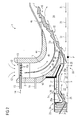
- FIG 1 the burner is depicted with the burner 1 having a housing 2 enclosing the burner components.
- Figure 2 shows for the sake of clarity a cross sectional view of the burner above a rotational symmetry axis.
- the main parts of the burner are the radial swirler 3, the multi quarl 4a, 4b, 4c and the pilot combustor 5.
- the burner loperates according to the principle of "supplying" heat and high concentration of free radicals from the a pilot combustor 5 exhaust 6 to a main flame 7 burning in a lean premixed air/fuel swirl emerging from a first exit 8 of a first lean premixing channel 10 and from a second exit 9 of a second lean premixing channel 11, whereby a rapid and stable combustion of the main lean premixed flame 7 is supported.
- Said first lean premixing channel 10 is formed by and between the walls 4a and 4b of the multi quarl.
- the second lean premixing channel 11 is formed by and between the walls 4b and 4c of the multi quarl.
- the outermost rotational symmetric wall 4c of the multi quarl is provided with an extension 4c1 to provide for the optimal length of the multi quarl arrangement.
- the first 10 and second 11 lean premixing channels are provided with swirler wings forming the swirler 3 to impart rotation to the air/fuel mixture passing through the channels.
- Air 12 is provided to the first 10 and second 11 channels at the inlet 13 of said first and second channels.
- the swirler 3 is located close to the inlet 13 of the first and second channels.
- fuel 14 is introduced to the air/fuel swirl through a tube 15 provided with small diffusor holes 15b located at the air 12 inlet 13 between the swirler 3 wings, whereby the fuel is distributed into the air flow through said holes as a spray and effectively mixed with the air flow. Additional fuel can be added through a second tube 16 emerging into the first channel 10.
- the flame 7 is generated as a conical rotational symmetric shear layer 18 around a main recirculation zone 20 (below sometimes abbreviated RZ).
- the flame 7 is enclosed inside the extension 4c1 of the outermost quarl, in this example quarl 4c.
- the pilot combustor 5 supplies heat and supplements a high concentration of free radicals directly to a forward stagnation point P and the shear layer 18 of the main swirl induced recirculation zone 20, where the main lean premixed flow is mixed with hot gases products of combustion provided by the pilot combustor 5.
- the pilot combustor 5 is provided with walls 21 enclosing a combustion room for a pilot combustion zone 22. Air is supplied to the combustion room through fuel channel 23 and air channel 24.
- a distributor plate 25 provided with holes over the surface of the plate. Said distributor plate 25 is separated a certain distance from said walls 21 forming a cooling space layer 25a. Cooling air 26 is taken in through a cooling inlet 27 and meets the outside of said distributor plate 25, whereupon the cooling air 26 is distributed across the walls 21 of the pilot combustor to effectively cool said walls 21.
- the cooling air 26 is after said cooling let out through a second swirler 28 arranged around a pilot quarl 29 of the pilot combustor 5.
- Further fuel can be added to the combustion in the main lean flame 7 by supplying fuel in a duct 30 arranged around and outside the cooling space layer 25a. Said further fuel is then let out and into the second swirler 28, where the now hot cooling air 26 and the fuel added through duct 30 is effectively premixed.
- a relatively large amount of fuel can be added to the small pilot combustor 5 cooling air which corresponds to very rich equivalence ratios ( ⁇ > 3).
- Swirled cooling air and fuel and hot products of combustion from the small pilot combustor can very effectively sustain combustion of the main lean flame 7 below, at and above LBO limits.
- the combustion process is very stable and efficient because hot combustion products and very hot cooling air (above 750 oC), premixed with fuel, provide heat and active species (radicals) to the forward stagnation point P of the main flame recirculation zone 20.
- the small pilot combustor 5 combined with very hot cooling air (above 750 oC) premixed with fuel act as a flameless burner, where reactants (oxygen & fuel ) are premixed with products of combustion and a distributed flame is established at the forward stagnation point P of the swirl induced recirculation zone 20.
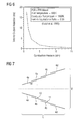
- the imparted level of swirl and the swirl number (equation 1) is above the critical one (not lower then 0.6 and not higher then 0.8, see also fig. 3 ) at which vortex breakdown - recirculation zone 20 - will form and will be firmly positioned within the multi quarl 4a, 4b, 4c arrangement.
- the forward stagnation point P should be located within the quarl 4a, 4b, 4c and at the exit 6 of the pilot combustor 5.
- the imparted level of swirl (the ratio between tangential and axial momentum) has to be higher then the critical one (0.4-0.6), so that a stable central recirculation zone 20 can form.
- the critical swirl number, SN is also a function of the burner geometry, which is the reason for why it varies between 0.4 and 0.6. If the imparted swirl number is ⁇ 0.4 or in the range of 0.4 to 0.6, the main recirculation zone 20, may not form at all or may form and extinguish periodically at low frequencies (below 150Hz) and the resulting aerodynamics could be very unstable which will result in a transient combustion process.
- flame stabilization can occur if: turbulent flame speed ( ST) > local velocity of the fuel air mixture (UF/A).
- Recirculating products which are: source of heat and active species (symbolized by means of arrows 1a and 1b), located within the recirculation zone 20, have to be stationary in space and time downstream from the mixing section of the burner 1 to enable pyrolysis of the incoming mixture of fuel and air. If a steady combustion process is not prevailing, thermo-acoustics instabilities will occur. Swirl stabilized flames are up to five times shorter and have significantly leaner blow-off limits then jet flames. A premixed or turbulent diffusion combustion swirl provides an effective way of premixing fuel and air.
- the entrainiment of the fuel/air mixture into the shear layer of the recirculation zone 20 is proportional to the strength of the recirculation zone, the swirl number and the characteristics recirculation zone velocity URZ.
- RZ strength MR exp - 1 / 2 dF / A / dF / A , cent ⁇ URZ / UF / A ⁇ b / dF / A , and MR should be ⁇ 1. (dF/A / dF/A,cent), only important for turbulent diffusion flames. recirculation zones size/length is "fixed" and proportional to 2-2.5 dF/A.
- the process is initiated and stabilized by means of transporting heat and free radicals 31 from the previously combusted fuel and air, back upstream towards the flame front 7.
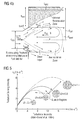
- the combustion process is very lean, as is the case in lean-partially premixed combustion systems, and as a result the combustion temperature is low, the equilibrium levels of free radicals is also very low.
- the free radicals produced by the combustion process quickly relax, see Fig. 6 , to the equilibrium level that corresponds to the temperature of the combustion products. This is due to the fact that the rate of this relaxation of the free radicals to equilibrium increases exponentially with increase in pressure, while on the other hand the equilibrium level of free radicals decreases exponentially with temperature decrease.
- the relaxation time of the free radicals can be short compared to the "transport" time required for the free radicals (symbolized by arrows 31) to be convected downstream, from the point where they were produced in the shear layer 18 of the main recirculation zone 20, back upstream, towards the flame front 7 and the forward stagnation point P of the main recirculation zone 20.
- This invention utilizes high non-equilibrium levels of free radicals 32 to stabilize the main lean combustion 7.
- the scale of the small pilot combustor 5 is kept small and most of the combustion of fuel occurs in the lean premixed main combustor (at 7 and 18), and not in the small pilot combustor 5.
- the small pilot combustor 5, can be kept small, because the free radicals 32 are released near the forward stagnation point P of the main recirculation zone 20. This is generally the most efficient location to supply additional heat and free radicals to swirl stabilized combustion (7).
- the time scale between quench and utilization of free radicals 32 is very short not allowing free radicals 32 to relax to low equilibrium levels.
- the forward stagnation point P of the main-lean re-circulating zone 20 is maintained and aerodynamically stabilized in the quarl (4a), at the exit 6 of the small pilot combustor 5.
- zone 22 the exit of the small pilot combustor 5 is positioned on the centerline and at the small pilot combustor 5 throat 33.
- the burner utilizes aerodynamics stabilization of the flame and confines the flame stabilization zone - recirculation zone (5), in the multiple quarl arrangement (4a, 4b and 4c).
- the multiple quarl (the term multiple quarl is herein sometimes used for multiple quarl sections defining the completed quarl of the burner) arrangement is an important feature of the disclosed burner design for the reasons listed below.
- the quarl (or sometimes called the diffuser):
- the quarl (or diffuser) and the imparted swirl provides a possibility of a simple scaling of the disclosed burner geometry for different burner powers.
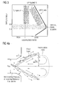
- the igniter 34 as in prior art burners, is placed in the outer recirculation zone, which is illustrated in Figure 4b , the fuel/air mixture entering this region must often be made rich in order to make the flame temperature sufficiently hot to sustain stable combustion in this region.
- the flame then often cannot be propagated to the main recirculation until the main premixed fuel and airflow becomes sufficiently rich, hot and has a sufficient pool of free radicals, which occurs at higher fuel flow rates.
- the flame cannot propagate from the outer recirculation zone to the inner main recirculation zone shortly after ignition, it must propagate at higher pressure after the engine speed begins to increase.
- the present invention also allows for the ignition of the main combustion 7 to occur at the forward stagnation point P of the main recirculation zone 20.
- Most gas turbine engines must use an outer recirculation zone, see Figure 4b , as the location where the spark, or torch igniter, ignites the engine. Ignition can only occur if stable combustion can also occur; otherwise the flame will just blow out immediately after ignition.
- the inner or main recirculation zone 22, as in the present invention, is generally more successful at stabilizing the flame, because the recirculated gas 31 is transported back and the heat from the combustion products of the recirculated gas 31 is focused to a small region at the forward stagnation point P of the main recirculation zone 20.
- the combustion - flame front 7 also expands outwards in a conical shape from this forward stagnation point P, as illustrated in Figure 2 .
- This conical expansion downstream allows the heat and free radicals 32 generated upstream to support the combustion downstream allowing the flame front 7 to widen as it moves downstream.
- the quarl (4a, 4b, 4c), illustrated in Figure 2 compared to swirl stabilized combustion without the quarl, shows how the quarl shapes the flame to be more conical and less hemispheric in nature.
- a more conical flame front allows for a point source of heat to initiate combustion of the whole flow field effectively.
- the combustion process within the burner 1 is staged.
- lean flame 35 is initiated in the small pilot combustor 5 by adding fuel 23 mixed with air 24 and igniting the mixture utilizing ignitor 34.
- ignition equivalence ratio of the flame 35 in the small pilot combustor 5 is adjusted at either lean (below equivalence ratio 1, and at approximately equivalence ratio of 0,8) or rich conditions (above equivalence ratio 1, and at approximately equivalence ratio between 1,4 and 1,6).
- lean low equivalence ratio 1, and at approximately equivalence ratio of 0,8
- rich conditions above equivalence ratio 1, and at approximately equivalence ratio between 1,4 and 1,6.
- the reason why the equivalence ratio within the small pilot combustor 5 is at rich conditions in the range between 1,4 and 1,6 is emission levels.
Priority Applications (7)
| Application Number | Priority Date | Filing Date | Title |
|---|---|---|---|
| EP08006666A EP2107311A1 (de) | 2008-04-01 | 2008-04-01 | Größenskalierung eines Brenners |
| CN2009801112622A CN101981379B (zh) | 2008-04-01 | 2009-03-26 | 燃烧器的尺寸缩放 |
| EP09728642.1A EP2263044B1 (de) | 2008-04-01 | 2009-03-26 | Grössenskalierung eines brenners |
| PCT/EP2009/053555 WO2009121776A1 (en) | 2008-04-01 | 2009-03-26 | Size scaling of a burner |
| US12/935,923 US20110027728A1 (en) | 2008-04-01 | 2009-03-26 | Size scaling of a burner |
| ES09728642T ES2417158T3 (es) | 2008-04-01 | 2009-03-26 | Ajuste a escala del tamaño de un quemador |
| RU2010144571/06A RU2455570C1 (ru) | 2008-04-01 | 2009-03-26 | Способ увеличения размера горелки и изменяемая по размеру огнеупорная амбразура в горелке |
Applications Claiming Priority (1)
| Application Number | Priority Date | Filing Date | Title |
|---|---|---|---|
| EP08006666A EP2107311A1 (de) | 2008-04-01 | 2008-04-01 | Größenskalierung eines Brenners |
Publications (1)
| Publication Number | Publication Date |
|---|---|
| EP2107311A1 true EP2107311A1 (de) | 2009-10-07 |
Family
ID=39810145
Family Applications (2)
| Application Number | Title | Priority Date | Filing Date |
|---|---|---|---|
| EP08006666A Withdrawn EP2107311A1 (de) | 2008-04-01 | 2008-04-01 | Größenskalierung eines Brenners |
| EP09728642.1A Not-in-force EP2263044B1 (de) | 2008-04-01 | 2009-03-26 | Grössenskalierung eines brenners |
Family Applications After (1)
| Application Number | Title | Priority Date | Filing Date |
|---|---|---|---|
| EP09728642.1A Not-in-force EP2263044B1 (de) | 2008-04-01 | 2009-03-26 | Grössenskalierung eines brenners |
Country Status (6)
| Country | Link |
|---|---|
| US (1) | US20110027728A1 (de) |
| EP (2) | EP2107311A1 (de) |
| CN (1) | CN101981379B (de) |
| ES (1) | ES2417158T3 (de) |
| RU (1) | RU2455570C1 (de) |
| WO (1) | WO2009121776A1 (de) |
Cited By (1)
| Publication number | Priority date | Publication date | Assignee | Title |
|---|---|---|---|---|
| WO2014110385A1 (en) * | 2013-01-11 | 2014-07-17 | Siemens Energy, Inc. | Lean-rich axial stage combustion in a can-annular gas turbine engine |
Families Citing this family (7)
| Publication number | Priority date | Publication date | Assignee | Title |
|---|---|---|---|---|
| ITMI20122154A1 (it) * | 2012-12-17 | 2014-06-18 | Ansaldo Energia Spa | Gruppo bruciatore, camera di combustione comprendente detto gruppo bruciatore e metodo per alimentare detto gruppo bruciatore |
| US8794217B1 (en) * | 2013-02-07 | 2014-08-05 | Thrival Tech, LLC | Coherent-structure fuel treatment systems and methods |
| JP6086860B2 (ja) | 2013-11-29 | 2017-03-01 | 三菱日立パワーシステムズ株式会社 | ノズル、燃焼器、及びガスタービン |
| US20150159877A1 (en) * | 2013-12-06 | 2015-06-11 | General Electric Company | Late lean injection manifold mixing system |
| US11174792B2 (en) | 2019-05-21 | 2021-11-16 | General Electric Company | System and method for high frequency acoustic dampers with baffles |
| US11156164B2 (en) | 2019-05-21 | 2021-10-26 | General Electric Company | System and method for high frequency accoustic dampers with caps |
| GB202013274D0 (en) * | 2020-08-25 | 2020-10-07 | Siemens Gas And Power Gmbh & Co Kg | Combuster for a gas turbine |
Citations (4)
| Publication number | Priority date | Publication date | Assignee | Title |
|---|---|---|---|---|
| GB812317A (en) * | 1956-05-18 | 1959-04-22 | Rene Leduc | Improvements in combustion chambers for gas turbines and ram-jets |
| US5321948A (en) * | 1991-09-27 | 1994-06-21 | General Electric Company | Fuel staged premixed dry low NOx combustor |
| JPH09264536A (ja) * | 1996-03-28 | 1997-10-07 | Toshiba Corp | ガスタービン燃焼器 |
| US20070113555A1 (en) * | 2004-08-27 | 2007-05-24 | Richard Carroni | Mixer Assembly |
Family Cites Families (46)
| Publication number | Priority date | Publication date | Assignee | Title |
|---|---|---|---|---|
| US2787120A (en) * | 1950-08-05 | 1957-04-02 | Leduc Rene | Plural annular coaxial combustion chambers |
| GB1048968A (en) * | 1964-05-08 | 1966-11-23 | Rolls Royce | Combustion chamber for a gas turbine engine |
| GB1421399A (en) * | 1972-11-13 | 1976-01-14 | Snecma | Fuel injectors |
| US3866413A (en) * | 1973-01-22 | 1975-02-18 | Parker Hannifin Corp | Air blast fuel atomizer |
| DE2460740C3 (de) * | 1974-12-21 | 1980-09-18 | Mtu Motoren- Und Turbinen-Union Muenchen Gmbh, 8000 Muenchen | Brennkammer für Gasturbinentriebwerke |
| US4204402A (en) * | 1976-05-07 | 1980-05-27 | The United States Of America As Represented By The Administrator Of The National Aeronautics And Space Administration | Reduction of nitric oxide emissions from a combustor |
| US4845940A (en) * | 1981-02-27 | 1989-07-11 | Westinghouse Electric Corp. | Low NOx rich-lean combustor especially useful in gas turbines |
| EP0114062A3 (de) * | 1983-01-18 | 1986-02-19 | Stubinen Utveckling AB | Verfahren und Vorrichtung zum Verbrennen fester Brennstoffe, insbesondere Kohle, Torf oder dergleichen, in pulverisierter Form |
| ATE42821T1 (de) * | 1985-03-04 | 1989-05-15 | Siemens Ag | Brenneranordnung fuer feuerungsanlagen, insbesondere fuer brennkammern von gasturbinenanlagen sowie verfahren zu ihrem betrieb. |
| JP2644745B2 (ja) * | 1987-03-06 | 1997-08-25 | 株式会社日立製作所 | ガスタービン用燃焼器 |
| JPH01114623A (ja) * | 1987-10-27 | 1989-05-08 | Toshiba Corp | ガスタービン燃焼器 |
| JPH0684817B2 (ja) * | 1988-08-08 | 1994-10-26 | 株式会社日立製作所 | ガスタービン燃焼器及びその運転方法 |
| US5040371A (en) * | 1988-12-12 | 1991-08-20 | Sundstrand Corporation | Fuel injectors for use with combustors |
| CH678757A5 (de) * | 1989-03-15 | 1991-10-31 | Asea Brown Boveri | |
| US5094082A (en) * | 1989-12-22 | 1992-03-10 | Sundstrand Corporation | Stored energy combustor |
| EP0550700B1 (de) * | 1990-10-05 | 1998-07-22 | Massachusetts Institute Of Technology | Verbrennungsanlage mit vermindertem ausstoss von stickstoffoxiden |
| GB9023004D0 (en) * | 1990-10-23 | 1990-12-05 | Rolls Royce Plc | A gas turbine engine combustion chamber and a method of operating a gas turbine engine combustion chamber |
| US5131334A (en) * | 1991-10-31 | 1992-07-21 | Monro Richard J | Flame stabilizer for solid fuel burner |
| GB2262981B (en) * | 1991-12-30 | 1995-08-09 | Ind Tech Res Inst | Dual fuel low nox burner |
| US5284438A (en) * | 1992-01-07 | 1994-02-08 | Koch Engineering Company, Inc. | Multiple purpose burner process and apparatus |
| JPH05203148A (ja) * | 1992-01-13 | 1993-08-10 | Hitachi Ltd | ガスタービン燃焼装置及びその制御方法 |
| US5237812A (en) * | 1992-10-07 | 1993-08-24 | Westinghouse Electric Corp. | Auto-ignition system for premixed gas turbine combustors |
| US5407347A (en) * | 1993-07-16 | 1995-04-18 | Radian Corporation | Apparatus and method for reducing NOx, CO and hydrocarbon emissions when burning gaseous fuels |
| US5394688A (en) * | 1993-10-27 | 1995-03-07 | Westinghouse Electric Corporation | Gas turbine combustor swirl vane arrangement |
| US5477685A (en) * | 1993-11-12 | 1995-12-26 | The Regents Of The University Of California | Lean burn injector for gas turbine combustor |
| GB2284884B (en) * | 1993-12-16 | 1997-12-10 | Rolls Royce Plc | A gas turbine engine combustion chamber |
| JP2950720B2 (ja) * | 1994-02-24 | 1999-09-20 | 株式会社東芝 | ガスタービン燃焼装置およびその燃焼制御方法 |
| US5647215A (en) * | 1995-11-07 | 1997-07-15 | Westinghouse Electric Corporation | Gas turbine combustor with turbulence enhanced mixing fuel injectors |
| US6201029B1 (en) * | 1996-02-13 | 2001-03-13 | Marathon Oil Company | Staged combustion of a low heating value fuel gas for driving a gas turbine |
| GB2311596B (en) * | 1996-03-29 | 2000-07-12 | Europ Gas Turbines Ltd | Combustor for gas - or liquid - fuelled turbine |
| US5983642A (en) * | 1997-10-13 | 1999-11-16 | Siemens Westinghouse Power Corporation | Combustor with two stage primary fuel tube with concentric members and flow regulating |
| US6109038A (en) * | 1998-01-21 | 2000-08-29 | Siemens Westinghouse Power Corporation | Combustor with two stage primary fuel assembly |
| US6354072B1 (en) * | 1999-12-10 | 2002-03-12 | General Electric Company | Methods and apparatus for decreasing combustor emissions |
| EP1710505A2 (de) * | 1999-12-15 | 2006-10-11 | Osaka Gas Co., Ltd. | Brenner, Gasturbinenantrieb und Kraft-Wärme-Kopplungsanlage |
| US6272840B1 (en) * | 2000-01-13 | 2001-08-14 | Cfd Research Corporation | Piloted airblast lean direct fuel injector |
| US6769903B2 (en) * | 2000-06-15 | 2004-08-03 | Alstom Technology Ltd | Method for operating a burner and burner with stepped premix gas injection |
| US6488496B1 (en) * | 2001-09-06 | 2002-12-03 | Hauck Manufacturing Co. | Compact combination burner with adjustable spin section |
| UA68446C2 (en) * | 2002-02-18 | 2004-08-16 | Res And Production Complex Of | Combustion chamber of gas turbine of power unit |
| US6820411B2 (en) * | 2002-09-13 | 2004-11-23 | The Boeing Company | Compact, lightweight high-performance lift thruster incorporating swirl-augmented oxidizer/fuel injection, mixing and combustion |
| US6969249B2 (en) * | 2003-05-02 | 2005-11-29 | Hauck Manufacturing, Inc. | Aggregate dryer burner with compressed air oil atomizer |
| DE10326720A1 (de) * | 2003-06-06 | 2004-12-23 | Rolls-Royce Deutschland Ltd & Co Kg | Brenner für eine Gasturbinenbrennkammer |
| JP3940705B2 (ja) * | 2003-06-19 | 2007-07-04 | 株式会社日立製作所 | ガスタービン燃焼器及びその燃料供給方法 |
| RU2407950C2 (ru) * | 2003-09-05 | 2010-12-27 | Делэвэн Инк | Горелка для камеры сгорания газовой турбины (варианты) |
| EP1659339A1 (de) * | 2004-11-18 | 2006-05-24 | Siemens Aktiengesellschaft | Verfahren zum Anfahren eines Brenners |
| US20080083224A1 (en) * | 2006-10-05 | 2008-04-10 | Balachandar Varatharajan | Method and apparatus for reducing gas turbine engine emissions |
| EP2107300A1 (de) * | 2008-04-01 | 2009-10-07 | Siemens Aktiengesellschaft | Dralleinrichtung mit Gasinjektor |
-
2008
- 2008-04-01 EP EP08006666A patent/EP2107311A1/de not_active Withdrawn
-
2009
- 2009-03-26 WO PCT/EP2009/053555 patent/WO2009121776A1/en active Application Filing
- 2009-03-26 US US12/935,923 patent/US20110027728A1/en not_active Abandoned
- 2009-03-26 RU RU2010144571/06A patent/RU2455570C1/ru not_active IP Right Cessation
- 2009-03-26 EP EP09728642.1A patent/EP2263044B1/de not_active Not-in-force
- 2009-03-26 ES ES09728642T patent/ES2417158T3/es active Active
- 2009-03-26 CN CN2009801112622A patent/CN101981379B/zh not_active Expired - Fee Related
Patent Citations (4)
| Publication number | Priority date | Publication date | Assignee | Title |
|---|---|---|---|---|
| GB812317A (en) * | 1956-05-18 | 1959-04-22 | Rene Leduc | Improvements in combustion chambers for gas turbines and ram-jets |
| US5321948A (en) * | 1991-09-27 | 1994-06-21 | General Electric Company | Fuel staged premixed dry low NOx combustor |
| JPH09264536A (ja) * | 1996-03-28 | 1997-10-07 | Toshiba Corp | ガスタービン燃焼器 |
| US20070113555A1 (en) * | 2004-08-27 | 2007-05-24 | Richard Carroni | Mixer Assembly |
Non-Patent Citations (1)
| Title |
|---|
| V. MILSAVLJEVIC ET AL.: "The influence of Burner Geometry and Flow Rates on the Stability and Symmetry of Swirl-Stabilized Nonpremixed Flames", COMBUSTION AND FLAME, vol. 80, 1990, pages 196 - 208 |
Cited By (2)
| Publication number | Priority date | Publication date | Assignee | Title |
|---|---|---|---|---|
| WO2014110385A1 (en) * | 2013-01-11 | 2014-07-17 | Siemens Energy, Inc. | Lean-rich axial stage combustion in a can-annular gas turbine engine |
| US9366443B2 (en) | 2013-01-11 | 2016-06-14 | Siemens Energy, Inc. | Lean-rich axial stage combustion in a can-annular gas turbine engine |
Also Published As
| Publication number | Publication date |
|---|---|
| CN101981379B (zh) | 2012-06-20 |
| ES2417158T3 (es) | 2013-08-06 |
| WO2009121776A1 (en) | 2009-10-08 |
| RU2010144571A (ru) | 2012-05-10 |
| EP2263044B1 (de) | 2013-05-15 |
| CN101981379A (zh) | 2011-02-23 |
| US20110027728A1 (en) | 2011-02-03 |
| RU2455570C1 (ru) | 2012-07-10 |
| EP2263044A1 (de) | 2010-12-22 |
Similar Documents
| Publication | Publication Date | Title |
|---|---|---|
| EP2257743B1 (de) | Brenner | |
| EP2107301B1 (de) | Gaseinspritzung in einem Brenner | |
| US8033112B2 (en) | Swirler with gas injectors | |
| EP2263043B1 (de) | Brennersteine in einem brenner | |
| EP2107312A1 (de) | Pilotverbrennkammer in einem Brenner | |
| EP2107313A1 (de) | Gestufte Brennstoffversorgung in einem Brenner | |
| EP2263044B1 (de) | Grössenskalierung eines brenners | |
| EP2434218A1 (de) | Brenner mit geringen NOx-Emissionen |
Legal Events
| Date | Code | Title | Description |
|---|---|---|---|
| PUAI | Public reference made under article 153(3) epc to a published international application that has entered the european phase |
Free format text: ORIGINAL CODE: 0009012 |
|
| AK | Designated contracting states |
Kind code of ref document: A1 Designated state(s): AT BE BG CH CY CZ DE DK EE ES FI FR GB GR HR HU IE IS IT LI LT LU LV MC MT NL NO PL PT RO SE SI SK TR |
|
| AX | Request for extension of the european patent |
Extension state: AL BA MK RS |
|
| AKX | Designation fees paid | ||
| REG | Reference to a national code |
Ref country code: DE Ref legal event code: 8566 |
|
| STAA | Information on the status of an ep patent application or granted ep patent |
Free format text: STATUS: THE APPLICATION IS DEEMED TO BE WITHDRAWN |
|
| 18D | Application deemed to be withdrawn |
Effective date: 20100408 |