EP0803681A1 - Optimalisierung der Durchmischung von Verbrennungsgasen in einer Gasturbinenbrennkammer - Google Patents
Optimalisierung der Durchmischung von Verbrennungsgasen in einer Gasturbinenbrennkammer Download PDFInfo
- Publication number
- EP0803681A1 EP0803681A1 EP97400928A EP97400928A EP0803681A1 EP 0803681 A1 EP0803681 A1 EP 0803681A1 EP 97400928 A EP97400928 A EP 97400928A EP 97400928 A EP97400928 A EP 97400928A EP 0803681 A1 EP0803681 A1 EP 0803681A1
- Authority
- EP
- European Patent Office
- Prior art keywords
- orifices
- combustion
- injectors
- row
- combustion chamber
- Prior art date
- Legal status (The legal status is an assumption and is not a legal conclusion. Google has not performed a legal analysis and makes no representation as to the accuracy of the status listed.)
- Granted
Links
- 239000007789 gas Substances 0.000 title claims abstract description 17
- 239000000567 combustion gas Substances 0.000 title claims abstract description 6
- 239000000203 mixture Substances 0.000 title 1
- 238000002485 combustion reaction Methods 0.000 claims abstract description 43
- 238000010790 dilution Methods 0.000 claims abstract description 19
- 239000012895 dilution Substances 0.000 claims abstract description 19
- 238000002347 injection Methods 0.000 claims abstract description 7
- 239000007924 injection Substances 0.000 claims abstract description 7
- 239000000446 fuel Substances 0.000 claims description 15
- 238000011144 upstream manufacturing Methods 0.000 claims description 4
- 238000007865 diluting Methods 0.000 claims description 2
- 238000000265 homogenisation Methods 0.000 description 2
- 230000001681 protective effect Effects 0.000 description 2
- UGFAIRIUMAVXCW-UHFFFAOYSA-N Carbon monoxide Chemical compound [O+]#[C-] UGFAIRIUMAVXCW-UHFFFAOYSA-N 0.000 description 1
- 241000861223 Issus Species 0.000 description 1
- 230000015572 biosynthetic process Effects 0.000 description 1
- 238000001816 cooling Methods 0.000 description 1
- 230000001627 detrimental effect Effects 0.000 description 1
- 230000000694 effects Effects 0.000 description 1
- 239000003546 flue gas Substances 0.000 description 1
- 239000007800 oxidant agent Substances 0.000 description 1
- 230000001590 oxidative effect Effects 0.000 description 1
- 230000035515 penetration Effects 0.000 description 1
- 230000001737 promoting effect Effects 0.000 description 1
- 238000005507 spraying Methods 0.000 description 1
Images
Classifications
-
- F—MECHANICAL ENGINEERING; LIGHTING; HEATING; WEAPONS; BLASTING
- F23—COMBUSTION APPARATUS; COMBUSTION PROCESSES
- F23R—GENERATING COMBUSTION PRODUCTS OF HIGH PRESSURE OR HIGH VELOCITY, e.g. GAS-TURBINE COMBUSTION CHAMBERS
- F23R3/00—Continuous combustion chambers using liquid or gaseous fuel
- F23R3/02—Continuous combustion chambers using liquid or gaseous fuel characterised by the air-flow or gas-flow configuration
- F23R3/04—Air inlet arrangements
- F23R3/10—Air inlet arrangements for primary air
- F23R3/12—Air inlet arrangements for primary air inducing a vortex
- F23R3/14—Air inlet arrangements for primary air inducing a vortex by using swirl vanes
-
- Y—GENERAL TAGGING OF NEW TECHNOLOGICAL DEVELOPMENTS; GENERAL TAGGING OF CROSS-SECTIONAL TECHNOLOGIES SPANNING OVER SEVERAL SECTIONS OF THE IPC; TECHNICAL SUBJECTS COVERED BY FORMER USPC CROSS-REFERENCE ART COLLECTIONS [XRACs] AND DIGESTS
- Y02—TECHNOLOGIES OR APPLICATIONS FOR MITIGATION OR ADAPTATION AGAINST CLIMATE CHANGE
- Y02T—CLIMATE CHANGE MITIGATION TECHNOLOGIES RELATED TO TRANSPORTATION
- Y02T50/00—Aeronautics or air transport
- Y02T50/60—Efficient propulsion technologies, e.g. for aircraft
Definitions
- the present invention relates to an annular combustion chamber of a turbomachine, said combustion chamber being delimited by an external ferrule and an internal ferrule joined at one of their ends by a chamber bottom and having, upstream, a combustion zone supplied with fuel by a plurality of injectors distributed regularly in the chamber bottom and associated with a plurality of air injection tendrils swirling the combustion gases around the geometric axes of the injectors, and downstream, a dilution zone in which dilution air is introduced by at least one row of orifices formed in the outer shell and by at least one row of orifices provided in the internal ferrule, said orifices being arranged in correspondence with the fuel injectors.
- the walls of the combustion chambers of aeronautical turbomachines have numerous air intake orifices in order to allow the combustion of the fuel injected into the chamber.
- Carburation combustion takes place in the combustion zone of the chamber.
- the primary oxidant is essentially supplied by the air injection tendrils and by various orifices provided in the chamber bottom.
- the dilution orifices are arranged in rows in transverse planes of the combustion chamber and are generally disposed opposite in the outer shell and in the inner shell.
- the first row of orifices called “primary orifices” is arranged between the combustion zone and the dilution zone. Part of the air introduced through the orifices of the first row recirculates towards the chamber bottom and participates in combustion; the other part enters the dilution zone and makes it possible to dilute the burnt gases from the lively combustion.
- This first row of orifices is followed downstream of one or more rows of orifices called "dilution orifices" introducing air into the dilution zone of the chamber.
- the arrangement vis-à-vis the primary or dilution orifices on the outer shell and the inner shell generates a blockage vis-à-vis the burnt gases coming from the bottom of the chamber. This is detrimental to the homogenization of the temperature of the burnt gases supplied to the turbine.
- the object of the present invention is to overcome this drawback, and therefore to improve the homogenization of the burnt gases.
- the orifices in the row of the outer shroud are offset in one direction in the transverse plane containing them, relative to the axial planes, passing through the axis of the injectors, and the orifices in the row of the internal shroud are offset in the other direction.
- the number of orifices in a row is twice the number of fuel injectors, these orifices are distributed in two series of alternating orifices of different diameters, the orifices of large diameter delivering a diluting air equicurrent with the direction of rotation of the tendrils and the orifices of reduced diameter delivering air against the current.
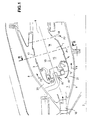
- the drawing shows an annular combustion chamber 1 of a gas turbine of axis 2.
- This combustion chamber 1 is delimited by an external ferrule 3 and an internal ferrule 4, these ferrules 3 and 4 being connected to one of their ends by a chamber bottom 5 and forming an annular passage 6 at their other ends for the evacuation of the burnt gases to a turbine not shown.
- Combustion chamber 1 is situated in a casing 7 delimited by an external wall 8 and an internal wall 9.
- a diffuser 10 delivers air, compressed by a compressor not shown, in the casing 7.
- the bottom of the chamber 5 is equipped with an injection device which comprises a plurality of fuel injectors 11 each associated with at least one air injection spin 12.
- the fuel injectors 11 are distributed regularly in the bottom of chamber 5, and the tendrils 12 impart to the combustion gases coming from each injector a vortex movement around the geometric axis 13 of this injector 12, in the direction represented by the arrow 14, all the gas vortices rotating in the same meaning.
- the combustion chamber has from upstream to downstream a primary zone or combustion zone 15 in which the fuel is burned, and a dilution zone 16 into which dilution air is introduced through orifices 17, 18 formed respectively in the outer shell 3 and the inner shell 4.
- the air flow F from the diffuser 10 is divided into several flows by the dome 19 which covers the chamber bottom 5.
- a first air flow F1 enters the dome 19 and is intended to participate actively in the spraying and combustion of the fuel delivered to the combustion chamber 1;
- a second flow F2 circulates in the annular space 20 delimited by the external ferrule 3 and the external wall 8
- a third air flow F3 circulates in the annular space 21 delimited by the internal ferrule 4 and the internal wall 9.
- the flows F2 and F3 participate in the cooling of the ferrules 3 and 4, and in the formation of the protective film. Most a large part of these flows F2 and F3 however enters the dilution zone through the orifices 17 and 18.
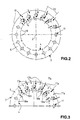
- the orifices 17 and 18 are distributed in rows of orifices in transverse planes P1, P2 substantially perpendicular to the geometric axes 13 of the fuel injectors 11.
- the transverse plane P1 is located at the border between the combustion zone 15 and the dilution zone 16. Part of the air entering through the orifices 17 and 18 located in the plane P1 recirculates towards the chamber bottom 5 and actively participates the combustion of the fuel in the combustion zone 15. The other part of the air entering through these same orifices 17 and 18 mixes with the gases burned in the dilution zone 16.
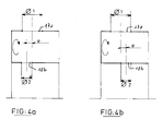
- the orifices 17 of the outer shell 3, located in the plane P1 are offset with respect to the axial planes 22 passing through the axis 2 of the turbomachine and the geometric axes 13 of the injectors 11 in the direction 14 of the vortices, that is to say in the clockwise direction, while the orifices 18 of the internal ferrule 4 are offset in the anticlockwise direction, that is to say - also say in the direction of the vortices.
- the air injected through the orifices 17 and 18 is equicurrent with the direction of rotation 14 of the tendrils 12.
- the offset value e is located between half the diameter of the large hole and half the diameter of the small hole ⁇ 2 2 ⁇ e ⁇ ⁇ 1 2
- the number of orifices 17 in an external row and the number of orifices 18 in an internal row is equal to the number of fuel injectors 11, and the vortices all rotate in the same direction, that is to say clockwise, if we look at the bottom of the chamber 5 from the downstream outlet 6 of the combustion chamber.
- the number of orifices in each row is twice the number of injectors 11 and the orifices 17 of the external shroud 3 are placed opposite the orifices 18 of the internal ferrule 4. But, as can be seen in FIG. 3, the orifices of each row are distributed in two series of orifices of different and alternating diameters.
- the large diameter holes, 17a on the outer shell 3 and 18a on the inner shell 4 deliver an air flow equicurrent with the direction of rotation 14 of the tendrils 12, while the reduced diameter holes, 17b on the outer shell 3 and 18b on the internal shroud 4, deliver a lower air flow against the current.
- the large diameter holes 17a are arranged opposite the reduced diameter holes 18b, while the reduced diameter holes 17b are located opposite the large diameter holes 18a.
Landscapes
- Engineering & Computer Science (AREA)
- Chemical & Material Sciences (AREA)
- Combustion & Propulsion (AREA)
- Mechanical Engineering (AREA)
- General Engineering & Computer Science (AREA)
- Nozzles (AREA)
Applications Claiming Priority (2)
| Application Number | Priority Date | Filing Date | Title |
|---|---|---|---|
| FR9605138 | 1996-04-24 | ||
| FR9605138A FR2748088B1 (fr) | 1996-04-24 | 1996-04-24 | Optimisation du melange de gaz brules dans une chambre de combustion annulaire |
Publications (2)
| Publication Number | Publication Date |
|---|---|
| EP0803681A1 true EP0803681A1 (de) | 1997-10-29 |
| EP0803681B1 EP0803681B1 (de) | 2003-07-09 |
Family
ID=9491527
Family Applications (1)
| Application Number | Title | Priority Date | Filing Date |
|---|---|---|---|
| EP97400928A Expired - Lifetime EP0803681B1 (de) | 1996-04-24 | 1997-04-24 | Optimierung der Durchmischung von Verbrennungsgasen in einer Gasturbinenbrennkammer |
Country Status (4)
| Country | Link |
|---|---|
| US (1) | US5934067A (de) |
| EP (1) | EP0803681B1 (de) |
| DE (1) | DE69723348T2 (de) |
| FR (1) | FR2748088B1 (de) |
Cited By (4)
| Publication number | Priority date | Publication date | Assignee | Title |
|---|---|---|---|---|
| WO2010081941A1 (fr) * | 2009-01-19 | 2010-07-22 | Snecma | Paroi de chambre de combustion de turbomachine à une seule rangée annulaire d'orifices d'entrée d'air primaire et de dilution |
| WO2012113553A1 (de) | 2011-02-25 | 2012-08-30 | Rolls-Royce Deutschland Ltd & Co Kg | Gasturbinenbrennkammer |
| EP2400220A3 (de) * | 2010-06-25 | 2015-07-22 | United Technologies Corporation | Wirbler, Kraftstoff- und Luftbaugruppe und Verbrenner |
| JP2017015389A (ja) * | 2016-10-06 | 2017-01-19 | 新潟原動機株式会社 | ガスタービン燃焼器 |
Families Citing this family (25)
| Publication number | Priority date | Publication date | Assignee | Title |
|---|---|---|---|---|
| DE59902355D1 (de) * | 1998-06-04 | 2002-09-19 | Siemens Ag | Brennstoffdüse |
| US6272865B1 (en) * | 1999-04-30 | 2001-08-14 | United Technologies Corporation | Swirler scoop and bearing plate for combustor |
| US6260359B1 (en) * | 1999-11-01 | 2001-07-17 | General Electric Company | Offset dilution combustor liner |
| DE10020598A1 (de) * | 2000-04-27 | 2002-03-07 | Rolls Royce Deutschland | Gasturbinenbrennkammer mit Zuleitungsöffnungen |
| US6606861B2 (en) * | 2001-02-26 | 2003-08-19 | United Technologies Corporation | Low emissions combustor for a gas turbine engine |
| US6675587B2 (en) * | 2002-03-21 | 2004-01-13 | United Technologies Corporation | Counter swirl annular combustor |
| ITMO20060202A1 (it) * | 2006-06-21 | 2007-12-22 | Galliano Bentivoglio | Pistola per erogare combustibile liquido |
| US7926284B2 (en) * | 2006-11-30 | 2011-04-19 | Honeywell International Inc. | Quench jet arrangement for annular rich-quench-lean gas turbine combustors |
| US20090090110A1 (en) * | 2007-10-04 | 2009-04-09 | Honeywell International, Inc. | Faceted dome assemblies for gas turbine engine combustors |
| US20100095649A1 (en) * | 2008-10-20 | 2010-04-22 | General Electric Company | Staged combustion systems and methods |
| US8739546B2 (en) | 2009-08-31 | 2014-06-03 | United Technologies Corporation | Gas turbine combustor with quench wake control |
| US8443610B2 (en) | 2009-11-25 | 2013-05-21 | United Technologies Corporation | Low emission gas turbine combustor |
| US9068751B2 (en) * | 2010-01-29 | 2015-06-30 | United Technologies Corporation | Gas turbine combustor with staged combustion |
| US8966877B2 (en) | 2010-01-29 | 2015-03-03 | United Technologies Corporation | Gas turbine combustor with variable airflow |
| US8479521B2 (en) | 2011-01-24 | 2013-07-09 | United Technologies Corporation | Gas turbine combustor with liner air admission holes associated with interspersed main and pilot swirler assemblies |
| US9068748B2 (en) | 2011-01-24 | 2015-06-30 | United Technologies Corporation | Axial stage combustor for gas turbine engines |
| US9958162B2 (en) | 2011-01-24 | 2018-05-01 | United Technologies Corporation | Combustor assembly for a turbine engine |
| US9127843B2 (en) * | 2013-03-12 | 2015-09-08 | Pratt & Whitney Canada Corp. | Combustor for gas turbine engine |
| US9541292B2 (en) | 2013-03-12 | 2017-01-10 | Pratt & Whitney Canada Corp. | Combustor for gas turbine engine |
| US9958161B2 (en) | 2013-03-12 | 2018-05-01 | Pratt & Whitney Canada Corp. | Combustor for gas turbine engine |
| US9228747B2 (en) * | 2013-03-12 | 2016-01-05 | Pratt & Whitney Canada Corp. | Combustor for gas turbine engine |
| US10816202B2 (en) | 2017-11-28 | 2020-10-27 | General Electric Company | Combustor liner for a gas turbine engine and an associated method thereof |
| US11255543B2 (en) | 2018-08-07 | 2022-02-22 | General Electric Company | Dilution structure for gas turbine engine combustor |
| CN114076324B (zh) * | 2022-01-19 | 2022-07-08 | 中国航发四川燃气涡轮研究院 | 能够自动调节掺混进气的燃烧室 |
| US12092324B2 (en) * | 2022-03-17 | 2024-09-17 | General Electric Company | Flare cone for a mixer assembly of a gas turbine combustor |
Citations (7)
| Publication number | Priority date | Publication date | Assignee | Title |
|---|---|---|---|---|
| GB623977A (en) * | 1946-06-24 | 1949-05-25 | Westinghouse Electric Int Co | Improvements in or relating to combustion apparatus |
| US2517015A (en) * | 1945-05-16 | 1950-08-01 | Bendix Aviat Corp | Combustion chamber with shielded fuel nozzle |
| US2807139A (en) * | 1953-01-19 | 1957-09-24 | Lucas Industries Ltd | Air-jacketed combustion chambers for jet propulsion engines, gas turbines and the like |
| GB1112357A (en) * | 1966-12-15 | 1968-05-01 | Rolls Royce | Flame tube |
| GB1462903A (en) * | 1973-07-27 | 1977-01-26 | Gen Motors Corp | Annular combustion apparatus |
| GB2020371A (en) * | 1978-05-04 | 1979-11-14 | Penny Turbines Ltd Noel | Gas turbine combustion chamber |
| EP0676590A1 (de) * | 1994-04-08 | 1995-10-11 | ROLLS-ROYCE plc | Gasturbinenbrennkammer |
-
1996
- 1996-04-24 FR FR9605138A patent/FR2748088B1/fr not_active Expired - Fee Related
-
1997
- 1997-04-21 US US08/845,133 patent/US5934067A/en not_active Expired - Lifetime
- 1997-04-24 EP EP97400928A patent/EP0803681B1/de not_active Expired - Lifetime
- 1997-04-24 DE DE69723348T patent/DE69723348T2/de not_active Expired - Lifetime
Patent Citations (7)
| Publication number | Priority date | Publication date | Assignee | Title |
|---|---|---|---|---|
| US2517015A (en) * | 1945-05-16 | 1950-08-01 | Bendix Aviat Corp | Combustion chamber with shielded fuel nozzle |
| GB623977A (en) * | 1946-06-24 | 1949-05-25 | Westinghouse Electric Int Co | Improvements in or relating to combustion apparatus |
| US2807139A (en) * | 1953-01-19 | 1957-09-24 | Lucas Industries Ltd | Air-jacketed combustion chambers for jet propulsion engines, gas turbines and the like |
| GB1112357A (en) * | 1966-12-15 | 1968-05-01 | Rolls Royce | Flame tube |
| GB1462903A (en) * | 1973-07-27 | 1977-01-26 | Gen Motors Corp | Annular combustion apparatus |
| GB2020371A (en) * | 1978-05-04 | 1979-11-14 | Penny Turbines Ltd Noel | Gas turbine combustion chamber |
| EP0676590A1 (de) * | 1994-04-08 | 1995-10-11 | ROLLS-ROYCE plc | Gasturbinenbrennkammer |
Cited By (8)
| Publication number | Priority date | Publication date | Assignee | Title |
|---|---|---|---|---|
| WO2010081941A1 (fr) * | 2009-01-19 | 2010-07-22 | Snecma | Paroi de chambre de combustion de turbomachine à une seule rangée annulaire d'orifices d'entrée d'air primaire et de dilution |
| FR2941287A1 (fr) * | 2009-01-19 | 2010-07-23 | Snecma | Paroi de chambre de combustion de turbomachine a une seule rangee annulaire d'orifices d'entree d'air primaire et de dilution |
| CN102282423A (zh) * | 2009-01-19 | 2011-12-14 | 斯奈克玛 | 具有用于主空气和稀释空气的单一环形行入孔的涡轮机燃烧室壁 |
| CN102282423B (zh) * | 2009-01-19 | 2014-06-18 | 斯奈克玛 | 具有用于主空气和稀释空气的单一环形行入孔的涡轮机燃烧室壁 |
| EP2400220A3 (de) * | 2010-06-25 | 2015-07-22 | United Technologies Corporation | Wirbler, Kraftstoff- und Luftbaugruppe und Verbrenner |
| US9562690B2 (en) | 2010-06-25 | 2017-02-07 | United Technologies Corporation | Swirler, fuel and air assembly and combustor |
| WO2012113553A1 (de) | 2011-02-25 | 2012-08-30 | Rolls-Royce Deutschland Ltd & Co Kg | Gasturbinenbrennkammer |
| JP2017015389A (ja) * | 2016-10-06 | 2017-01-19 | 新潟原動機株式会社 | ガスタービン燃焼器 |
Also Published As
| Publication number | Publication date |
|---|---|
| DE69723348T2 (de) | 2004-06-09 |
| EP0803681B1 (de) | 2003-07-09 |
| US5934067A (en) | 1999-08-10 |
| FR2748088A1 (fr) | 1997-10-31 |
| FR2748088B1 (fr) | 1998-05-29 |
| DE69723348D1 (de) | 2003-08-14 |
Similar Documents
| Publication | Publication Date | Title |
|---|---|---|
| EP0803681B1 (de) | Optimierung der Durchmischung von Verbrennungsgasen in einer Gasturbinenbrennkammer | |
| EP0828115B1 (de) | Brennstoffeinspritzsystem für eine Brennkammer | |
| CA2646959C (fr) | Systeme d'injection d'un melange d'air et de carburant dans une chambre de combustion de turbomachine | |
| CA2588952C (fr) | Chambre de combustion d'une turbomachine | |
| EP0818658B1 (de) | Ringbrennkammer mit reduzierter Nox-Produktion | |
| EP0743490B1 (de) | Brennkammer mit einer Vielzahl von Filmkühlungsbohrungen die in verschiedene axiale und tangentiale Richtungen geneigt sind | |
| FR2968354A1 (fr) | Procede pour faire fonctionner une buse de diffusion a etagement d'air | |
| FR2968353A1 (fr) | Buse de diffusion a etagement d'air | |
| EP0592305A1 (de) | Nachverbrenner für Zweistromtriebwerk | |
| CH631800A5 (fr) | Chambre de combustion pour turbine a gaz. | |
| FR2911667A1 (fr) | Systeme d'injection de carburant a double injecteur. | |
| FR2967479A1 (fr) | Dispositif et procede pour l'allumage d'un systeme de combustion | |
| FR2970553A1 (fr) | Systeme de regulation de debit dans un injecteur multitubulaire de combustible | |
| FR2933766A1 (fr) | Dispositif de premelange pour moteur a turbine. | |
| FR2941287A1 (fr) | Paroi de chambre de combustion de turbomachine a une seule rangee annulaire d'orifices d'entree d'air primaire et de dilution | |
| FR2772890A1 (fr) | Ensemble de melange d'air et de combustible et moteur a turbine a gaz le comportant | |
| FR2709342A1 (fr) | Dispositif de post combustion d'un turboréacteur. | |
| EP3569929A1 (de) | Einheit für eine brennkammer eines turbotriebwerks | |
| EP1593911B1 (de) | Zündluft- und Kraftstoffzuführvorrichtung für Brennerring eines Nachbrenner | |
| FR2594212A1 (fr) | Bruleur pour la combustion d'un melange combustible/air, comprenant une pluralite d'ailettes qui s'etendent dans le sens de l'axe d'ecoulement du melange | |
| FR2996287A1 (fr) | Dispositif d'injection pour une chambre de combustion de turbomachine | |
| US4144710A (en) | Gas turbine engine | |
| EP0368829B1 (de) | Brenner für festen Brennstoff | |
| EP3359880B1 (de) | Ringförmige brennkammer für einen turbinenmotor | |
| EP3830486A1 (de) | Brennkammer mit einem durchgangsabschnitt eines flammrohrs, das modifiziert ist; insbesondere für eine turbine zur erzeugung von leistung, insbesondere elektrischem strom |
Legal Events
| Date | Code | Title | Description |
|---|---|---|---|
| PUAI | Public reference made under article 153(3) epc to a published international application that has entered the european phase |
Free format text: ORIGINAL CODE: 0009012 |
|
| 17P | Request for examination filed |
Effective date: 19970510 |
|
| AK | Designated contracting states |
Kind code of ref document: A1 Designated state(s): DE FR GB |
|
| 17Q | First examination report despatched |
Effective date: 20020517 |
|
| GRAH | Despatch of communication of intention to grant a patent |
Free format text: ORIGINAL CODE: EPIDOS IGRA |
|
| RTI1 | Title (correction) |
Free format text: OPTIMISATION OF THE MIXTURE OF COMBUSTION GAS IN A GAS TURBINE COMBUSTOR |
|
| GRAH | Despatch of communication of intention to grant a patent |
Free format text: ORIGINAL CODE: EPIDOS IGRA |
|
| GRAA | (expected) grant |
Free format text: ORIGINAL CODE: 0009210 |
|
| RAP1 | Party data changed (applicant data changed or rights of an application transferred) |
Owner name: SNECMA MOTEURS |
|
| AK | Designated contracting states |
Designated state(s): DE FR GB |
|
| REG | Reference to a national code |
Ref country code: GB Ref legal event code: FG4D Free format text: NOT ENGLISH |
|
| REF | Corresponds to: |
Ref document number: 69723348 Country of ref document: DE Date of ref document: 20030814 Kind code of ref document: P |
|
| GBT | Gb: translation of ep patent filed (gb section 77(6)(a)/1977) | ||
| PLBE | No opposition filed within time limit |
Free format text: ORIGINAL CODE: 0009261 |
|
| STAA | Information on the status of an ep patent application or granted ep patent |
Free format text: STATUS: NO OPPOSITION FILED WITHIN TIME LIMIT |
|
| 26N | No opposition filed |
Effective date: 20040414 |
|
| REG | Reference to a national code |
Ref country code: FR Ref legal event code: CD |
|
| PGFP | Annual fee paid to national office [announced via postgrant information from national office to epo] |
Ref country code: GB Payment date: 20150324 Year of fee payment: 19 |
|
| PGFP | Annual fee paid to national office [announced via postgrant information from national office to epo] |
Ref country code: DE Payment date: 20150319 Year of fee payment: 19 |
|
| REG | Reference to a national code |
Ref country code: FR Ref legal event code: PLFP Year of fee payment: 20 |
|
| PGFP | Annual fee paid to national office [announced via postgrant information from national office to epo] |
Ref country code: FR Payment date: 20160407 Year of fee payment: 20 |
|
| REG | Reference to a national code |
Ref country code: DE Ref legal event code: R119 Ref document number: 69723348 Country of ref document: DE |
|
| GBPC | Gb: european patent ceased through non-payment of renewal fee |
Effective date: 20160424 |
|
| PG25 | Lapsed in a contracting state [announced via postgrant information from national office to epo] |
Ref country code: DE Free format text: LAPSE BECAUSE OF NON-PAYMENT OF DUE FEES Effective date: 20161101 Ref country code: GB Free format text: LAPSE BECAUSE OF NON-PAYMENT OF DUE FEES Effective date: 20160424 |
|
| REG | Reference to a national code |
Ref country code: FR Ref legal event code: CD Owner name: SAFRAN AIRCRAFT ENGINES Effective date: 20170719 |