EP0803673A2 - Soupape à gaz - Google Patents
Soupape à gaz Download PDFInfo
- Publication number
- EP0803673A2 EP0803673A2 EP97106432A EP97106432A EP0803673A2 EP 0803673 A2 EP0803673 A2 EP 0803673A2 EP 97106432 A EP97106432 A EP 97106432A EP 97106432 A EP97106432 A EP 97106432A EP 0803673 A2 EP0803673 A2 EP 0803673A2
- Authority
- EP
- European Patent Office
- Prior art keywords
- gas
- liquid
- valve according
- valve
- magnetic
- Prior art date
- Legal status (The legal status is an assumption and is not a legal conclusion. Google has not performed a legal analysis and makes no representation as to the accuracy of the status listed.)
- Granted
Links
Images



Classifications
-
- F—MECHANICAL ENGINEERING; LIGHTING; HEATING; WEAPONS; BLASTING
- F16—ENGINEERING ELEMENTS AND UNITS; GENERAL MEASURES FOR PRODUCING AND MAINTAINING EFFECTIVE FUNCTIONING OF MACHINES OR INSTALLATIONS; THERMAL INSULATION IN GENERAL
- F16K—VALVES; TAPS; COCKS; ACTUATING-FLOATS; DEVICES FOR VENTING OR AERATING
- F16K13/00—Other constructional types of cut-off apparatus; Arrangements for cutting-off
- F16K13/08—Arrangements for cutting-off not used
- F16K13/10—Arrangements for cutting-off not used by means of liquid or granular medium
-
- F—MECHANICAL ENGINEERING; LIGHTING; HEATING; WEAPONS; BLASTING
- F16—ENGINEERING ELEMENTS AND UNITS; GENERAL MEASURES FOR PRODUCING AND MAINTAINING EFFECTIVE FUNCTIONING OF MACHINES OR INSTALLATIONS; THERMAL INSULATION IN GENERAL
- F16K—VALVES; TAPS; COCKS; ACTUATING-FLOATS; DEVICES FOR VENTING OR AERATING
- F16K31/00—Actuating devices; Operating means; Releasing devices
- F16K31/02—Actuating devices; Operating means; Releasing devices electric; magnetic
- F16K31/06—Actuating devices; Operating means; Releasing devices electric; magnetic using a magnet, e.g. diaphragm valves, cutting off by means of a liquid
-
- Y—GENERAL TAGGING OF NEW TECHNOLOGICAL DEVELOPMENTS; GENERAL TAGGING OF CROSS-SECTIONAL TECHNOLOGIES SPANNING OVER SEVERAL SECTIONS OF THE IPC; TECHNICAL SUBJECTS COVERED BY FORMER USPC CROSS-REFERENCE ART COLLECTIONS [XRACs] AND DIGESTS
- Y10—TECHNICAL SUBJECTS COVERED BY FORMER USPC
- Y10S—TECHNICAL SUBJECTS COVERED BY FORMER USPC CROSS-REFERENCE ART COLLECTIONS [XRACs] AND DIGESTS
- Y10S137/00—Fluid handling
- Y10S137/909—Magnetic fluid valve
-
- Y—GENERAL TAGGING OF NEW TECHNOLOGICAL DEVELOPMENTS; GENERAL TAGGING OF CROSS-SECTIONAL TECHNOLOGIES SPANNING OVER SEVERAL SECTIONS OF THE IPC; TECHNICAL SUBJECTS COVERED BY FORMER USPC CROSS-REFERENCE ART COLLECTIONS [XRACs] AND DIGESTS
- Y10—TECHNICAL SUBJECTS COVERED BY FORMER USPC
- Y10T—TECHNICAL SUBJECTS COVERED BY FORMER US CLASSIFICATION
- Y10T137/00—Fluid handling
- Y10T137/206—Flow affected by fluid contact, energy field or coanda effect [e.g., pure fluid device or system]
- Y10T137/2082—Utilizing particular fluid
-
- Y—GENERAL TAGGING OF NEW TECHNOLOGICAL DEVELOPMENTS; GENERAL TAGGING OF CROSS-SECTIONAL TECHNOLOGIES SPANNING OVER SEVERAL SECTIONS OF THE IPC; TECHNICAL SUBJECTS COVERED BY FORMER USPC CROSS-REFERENCE ART COLLECTIONS [XRACs] AND DIGESTS
- Y10—TECHNICAL SUBJECTS COVERED BY FORMER USPC
- Y10T—TECHNICAL SUBJECTS COVERED BY FORMER US CLASSIFICATION
- Y10T137/00—Fluid handling
- Y10T137/206—Flow affected by fluid contact, energy field or coanda effect [e.g., pure fluid device or system]
- Y10T137/218—Means to regulate or vary operation of device
- Y10T137/2191—By non-fluid energy field affecting input [e.g., transducer]
-
- Y—GENERAL TAGGING OF NEW TECHNOLOGICAL DEVELOPMENTS; GENERAL TAGGING OF CROSS-SECTIONAL TECHNOLOGIES SPANNING OVER SEVERAL SECTIONS OF THE IPC; TECHNICAL SUBJECTS COVERED BY FORMER USPC CROSS-REFERENCE ART COLLECTIONS [XRACs] AND DIGESTS
- Y10—TECHNICAL SUBJECTS COVERED BY FORMER USPC
- Y10T—TECHNICAL SUBJECTS COVERED BY FORMER US CLASSIFICATION
- Y10T137/00—Fluid handling
- Y10T137/4456—With liquid valves or liquid trap seals
- Y10T137/4643—Liquid valves
Definitions
- the invention relates to a gas-flow valve with at least one gas inlet and at least one gas outlet.
- Hitherto customary gas-flow valves have one or more shut-off bodies between the gas inlet and the gas outlet, which, depending on their position, allow gas to flow through the valve or interrupt the flow path.
- the movable shut-off bodies must be tolerated accordingly so that no leakage currents occur in the shut-off position of the valve.
- the gas-flow valves that have been customary up to now are usually complex to manufacture.
- the object of the invention is therefore to create a simply constructed valve through which gas flows.
- a magnetic liquid is provided in the flow path between the gas inlet and gas outlet in the valve, which solidifies when a magnetic field is applied and the flow path from at least one gas inlet to or interrupts gas-tight and gas can flow through without an applied magnetic field.
- the gas-flow-through valve according to the invention works with a magnetic liquid instead of a movable slide body or a special shut-off body and is therefore very simple in construction and very robust since it is not subject to wear.
- Magnetic liquids are stable disperse systems that contain modified magnetic particles the size of a few nanometers as the dispersed phase.
- water, hydrocarbons or vacuum and dispersion oils can be used as dispersion carriers.
- various magnetic liquids can be produced, which can be optimized for a particular purpose.
- Magnetic liquids have hitherto been used, for example, in magnetohydrostatic separation, in which the magnetically induced buoyancy of non-metals in the magnetic liquid, which is dependent on the density and the magnetic field gradient, is used to separate the non-metals. Magnetic liquids are also used to seal, store, damp and relieve waves. Magnetic liquids are used in automotive engineering, among others. for setting different damping of vehicles, since different degrees of hardness can be generated by different sized magnetic fields, which result in different viscosities of the magnetic liquid.
- the present invention provides the use of the magnetic fluid for switching a gas valve by utilizing the change in viscosity of the magnetic fluid by applying a magnetic field. If no or only a small magnetic field is applied, remains the magnetic liquid is liquid and homogeneous. In this state, a gas can flow from the gas inlet through the liquid to the gas outlet. By applying a sufficiently strong magnetic field, however, the magnetic liquid changes from the liquid to the solid state, in which the gas is shut off by the solidified magnetic liquid.
- the magnetic fluid is attracted to the magnetic field, ie a displaceable magnet can be used specifically to block or open individual inlets or outlets. It is also conceivable to apply an only moderately strong magnetic field, by means of which the magnetic liquid does not completely block the gas flow and allows partial gas passage, so that the amount of gas flowing through the valve according to the invention can be continuously adjusted.
- the first principle provides that the liquid level is matched to the gas inlet and the gas outlet in such a way that gas flows through the liquid when the gas inlet and the gas outlet are open.
- gas does not flow through the liquid when the valve is open.
- the magnetic field acts in such a direction and strength on the magnetic liquid that it is displaced in the region of the gas inlet and / or gas outlet, so that gas without flowing through the liquid can flow directly from the gas inlet to the gas outlet.
- the magnetic field attracts or repels the liquid, the magnetic liquid being displaceable so that it has an oblique liquid surface rather than a horizontal one.
- the valve according to the invention can be, for example, a 2/2-way valve.
- An embodiment of the invention further provides that a pressure vessel is provided between the gas inlet and the gas outlet, which is at least partially with the magnetic Liquid is filled into which an inlet pipe protrudes, with a part of the inlet pipe extending beyond the liquid level. The part of the inlet pipe which extends over the liquid level prevents the liquid from flowing out of the pressure vessel via the gas-carrying inlet pipe.
- the inlet pipe can be arcuate and protrude with its inlet end from above into the liquid or additionally extend from below through a base and a section of the pressure vessel filled with liquid to above the liquid level and from there back down into the liquid. In addition, it is possible to guide the inlet pipe into the liquid through an upper side of the pressure vessel.
- the pressure vessel is preferably cylindrical or cuboid and can be provided with a rounded lower part, the gas outlet being provided at the top of the pressure vessel in one embodiment.
- the magnetic field can be generated in different ways.
- a permanent magnet which can be moved towards and away from the magnetic liquid can be provided, which, according to a preferred embodiment, surrounds the pressure vessel in a ring, for example, and can be displaced from an unactuated to an actuated position parallel to its lateral surface. In the actuated position, the permanent magnet at least partially encloses the part of the pressure vessel filled with magnetic liquid.
- the permanent magnet is displaceable on the outer surface of the pressure vessel, a separate construction with parallel guides for displacing the permanent magnet can be omitted.
- the second way to generate a magnetic field is to provide a switchable electromagnet.
- the electromagnet too preferably at least partially encloses the part of the pressure vessel filled with magnetic liquid.
- the magnetic liquid is thus also arranged in the interior of the coil of the electromagnet, where the magnetic field is particularly strong.
- the magnet which can be designed both as a permanent magnet and as an electromagnet, can be arranged in a stepless manner or can be locked in several positions in order to specifically interrupt the gas flow in one or more suitably arranged inlets or outlets or allow.
- non-magnetic particles such as e.g. Add plastics, rubber or diamagnetic or paramagnetic metals such as copper or aluminum that support the switching of the valve.
- the non-magnetic particles can receive a magnetic buoyancy in the magnetic liquid which is dependent on their density and the magnetic field gradient and are thus pushed to the upper edge of the magnetic liquid.
- particles without magnetic buoyancy can be provided which are pressed against one another by the change in viscosity when a magnetic field is applied. In any case, the provision of such non-magnetic particles results in an accelerated and improved shut-off effect of the valve.
- surfactants are preferably present in the magnetic liquid which, because of their molecular structure, have a surface-active effect and are used as wetting agents, esters or fatty acids being particularly suitable.
- a magnetic liquid for a gas-flow valve is not only limited to a one-way valve, but the invention also creates a gas-flowed 3/2-way and multi-way valve by several previously described valves are connected accordingly.
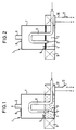
- Figures 1 to 4 show a gas-flow valve 1, which is designed as a 2/2-way valve.
- a cylindrical pressure vessel 7 is provided, which is partially filled with a magnetic liquid 3.
- an electromagnet 9 in the form of a coil surrounds the part of the pressure vessel 7 which is filled with liquid.
- the electromagnet 9 is connected via lines 10 to a voltage source, the connection being able to be established or interrupted depending on the position of a switch 12.
- the cylindrical shape of the pressure vessel allows the valve 1 together with its electromagnet 9, which is simple in terms of production technology, to surround the pressure vessel 7 in an annular manner and adjoin it.
- An inlet pipe 11 extends through an opening in the outer surface of the pressure vessel 7 into the magnetic liquid 3 and further in an arc over the liquid level 5 in order to finally protrude into the liquid 3 from above with its gas inlet 2. Because part of the inlet pipe 11 rises above the liquid level 5, no magnetic liquid 3 can flow out of the pressure vessel 7 via the inlet pipe 11.
- a gas outlet 6 is located on the top 8 of the pressure vessel 7.
- the switch 12 is in the open state, that is to say that the electromagnet 9 is not connected to the voltage source and does not generate a magnetic field.
- the magnetic liquid 3 is in the liquid phase, with non-magnetic particles 4 being very finely distributed in the magnetic liquid 3.
- Water is used as the dispersion carrier for the magnetic particles present in the magnetic liquid 3. Since the magnetic liquid 3 according to FIG. 1 is in its liquid phase, gas can flow through the liquid 3 via the inlet pipe 11 and the gas inlet 2.
- the area of the interior of the pressure vessel 7 that is not with Liquid 3 is filled, is filled with gas, which can flow to a consumer via the gas outlet 6.
- the switch 12 must also be closed, as shown in FIG. 2, so that the electromagnet 9 generates a magnetic field which acts on the magnetic liquid 3.
- the magnetic field is so strong that there is a change in viscosity of the magnetic liquid 3 and a phase transition from liquid to solid.
- the non-magnetic particles present in the magnetic liquid 3, preferably in the form of elastomers, are selected such that they receive a magnetic buoyancy in the liquid 3 in this state and are pushed to the liquid level 5 and pressed together where they form an additional barrier layer .
- the solidified magnetic liquid 3 does not allow gas to flow through and completely interrupts the gas flow.
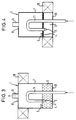
- FIG. 3 and 4 corresponds essentially to the previously explained embodiment, but instead of the electromagnet 9, a permanent magnet 19 is provided, which is arranged vertically displaceably on the outer surface of the pressure vessel 7, so that the outer surface for storage Permanent magnet 19 represents.
- the inlet pipe 11 extends from below through a base 13 of the pressure vessel 7 inside it.
- the permanent magnet 19 is arranged in the upper region of the pressure vessel 7.
- the magnetic field generated by it is so far away from the magnetic liquid 3 that it is too weak to convert the liquid 3 present in the liquid phase in FIG. 3 into the solid phase or to draw it into areas with a stronger magnetic field.
- the permanent magnet 19 is pushed down according to FIG. 4, so that it is the part filled with liquid 3 of the pressure vessel 7, the processes explained in connection with FIG. 2 take place in the liquid 3, and the valve 1 assumes its closed position.
- the surfactants also present in the liquid 3 have a surface-active effect and prevent a kind of lump formation from non-magnetic particles.
- valves 1 in which electromagnets 9 and additionally permanent magnets 19 are present.
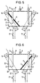
- FIGS. 5 and 6 show a valve 1 through which gas flows and which is designed as a 3/2-way valve.
- a cylindrical pressure vessel 7 is provided, which is partially filled with a magnetic liquid 3.
- a magnetic liquid 3 protrude from above through openings in the top 8 of the pressure vessel 7, an inlet pipe 11 with a gas inlet 2 and a vent pipe 14.
- a gas outlet 6 is located on the top 8 of the pressure vessel 7.
- two electromagnets 9, 16 are arranged in the form of coils such that one encloses the area of the gas inlet 2, the second the area of the gas inlet 23.
- the electromagnets 9 and 16 are not included in the drawing via lines 10 and 22, respectively shown voltage sources connected, the circuits can be closed or interrupted depending on the position of the switches 12, 21.
- Two of the four possible switch positions of the switches 12, 21 are used to implement the 3/2-way valve, namely the switch position switch 12 open, switch 21 closed (FIG. 5) and the switch position switch 12 closed, switch 21 open (FIG 6).
- FIGS. 5 and 6 is the circuit of the Electromagnets 16 closed, that is to say that the electromagnet 16 generates a magnetic field which pulls the magnetic liquid 3 into the region of the gas inlet 23 and there it changes from the liquid to the solid phase.
- the non-magnetic particles 4 distributed in the liquid phase are forced outward from the magnetic field, ie to the liquid surface, which is represented by the obliquely running liquid level 5, where they form an additional barrier layer.
- the solidified magnetic liquid 3 does not allow gas to flow through and completely seals the ventilation pipe 14. The gas can flow freely between the inlet pipe 11 and the gas outlet 6, the valve 1 is open.
- the circuit of the electromagnet 9 is closed via the switch 12, whereas the circuit of the electromagnet 16 is interrupted by the switch 21.
- the electromagnet 9 generates a magnetic field which pulls the magnetic liquid 3 into the area of the gas inlet 2 so that it changes from the liquid to the solid phase there.
- the barrier layer also consists of non-magnetic particles 3.
- the gas flow through the inlet pipe 11 is completely interrupted, the valve 1 is closed. However, gas can flow through the pressure vessel 7 between the gas outlet 6 and the vent pipe 14, i.e. valve 1 is vented.
- FIGS. 7 to 10 essentially corresponds to the embodiment explained in FIGS. 5 and 6, but instead of the vent pipe 14, a second inlet pipe 15 projects into the magnetic liquid 3 from above.
- the two inlet pipes 11, 15 can be alternately closed or opened by an associated magnetic field or switched together.
- a valve 1 with a mixing function is created.
- the inlet pipe 15 is closed by the action of the magnetic field of the electromagnet 16. Gas can flow freely between the inlet pipe 11 and the gas outlet 6.
- Fig. 8 shows the reverse function.
- the inlet pipe 11 is closed by the action of the magnetic field of the electromagnet 9 and gas can flow freely between the inlet pipe 15 and the gas outlet 6.
- Fig. 9 the circuits of both electromagnets 9, 16 are closed. Due to the action of the magnetic fields, the magnetic liquid 3 is drawn to the inlet pipes 11 and 15, respectively, and this completely seals off the gas inlets 2 and 23 through the previously described processes in the magnetic liquid 3, the valve 1 is closed. Part of the liquid 3 is pushed to the left side of the pressure vessel 7 in order to close the gas inlet 23 in the case of an inclined, gas-tight liquid surface 5. The remaining other part of the liquid 3 is pushed to the right side of the pressure vessel 7 in order to close the gas inlet 2 there when the gas-tight liquid surface runs obliquely.
- switches 12 and 21 are open, i.e. electromagnets 9 and 16 do not generate magnetic fields.
- the magnetic liquid 3 is in the liquid phase and allows gases to flow from both gas inlets 2, 23 to the gas outlet 6.
- FIGS. 11 to 14 show an embodiment which essentially corresponds to the embodiment shown in FIGS. 7 to 10.
- the changed arrangement creates a valve 1 with a distributor function.
- the inlet pipe 11 is arranged between two outlet pipes 17, 18, so that in the event that there is no magnetic field, the gas inlet 2 and ends 24 and 25 of the outlet pipes 17 and 18 protrude into the magnetic liquid 3.
- Fig. 11 the circuit of the electromagnet 16 is closed by closing the switch 21.
- the circuit of the electromagnet 9, however, is open.
- the electromagnet 16 generates a magnetic field in the region of the end 24.
- the magnetic fluid 3 is drawn into this region by the action of the magnetic field and solidifies there.
- the above-mentioned internal processes completely seal the gas outlet 17, whereas gas from the inlet pipe 11 can flow out of the pressure vessel 7 via the outlet pipe 18 without having to flow through magnetic liquid.
- Fig. 12 shows the reverse function of the valve 1.
- the outlet pipe 18 is shut off by the magnetic field generated by the electromagnet 9. Gas can flow from the inlet pipe 11 via the outlet pipe 17 out of the pressure vessel 7.
- Fig. 13 the switches 12 and 21 are closed.
- the electromagnets 9 and 16 generate magnetic fields which pull the magnetic liquid 3 into the regions of the ends 24 and 25 and this changes into the solid phase.
- the two outlet pipes 17 and 18 are completely shut off by the internal processes already described in the magnetic liquid 3, the valve 1 is in the blocking function.
- the circuits of the electromagnets 9 and 16 are open, so that no magnetic field acts on the magnetic liquid 3.
- gas can flow from the inlet pipe 11 through the liquid 3 and the outlet pipes 17, 18. In this case, the gas is distributed to both outlet pipes 17 and 18.
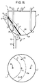
- FIGS. 15 and 16 show a further embodiment of a valve 1, which is designed as a multi-way valve with a mixing function and has four inlet pipes 11, 15, 26 and 27 and a gas outlet 6. Operation of the valve 1 corresponds essentially to that of the valve 1 illustrated in FIGS. 7 to 10.
- the shut-off or opening of individual inlet pipes 11, 15, 26, 27 takes place by means of the electromagnet 9, which is attached to the hemispherical lower part 13 'of the valve 1 about the vertical longitudinal axis of the Pressure vessel 7 can be rotated horizontally (see arrow A) and / or can be moved about the lower end of the hemispherical part 13 '(see arrow B).
- the corresponding guidance of the electromagnet 9 is not shown.
- the electromagnet 9 can be locked in several positions or even continuously. Instead of the electromagnet 9, a permanent magnet can also be provided.
- the annular electromagnet 9 is slidably supported by a guide (not shown) such that its magnetic field only reaches the area of a gas inlet 2. Due to the action of the magnetic field, the solidified magnetic liquid 3 shuts off the inlet pipe 15. If the liquid level 5 is brought to the liquid level 5a by adding liquid 3 via a filler tube (not shown), depending on the liquid level 5a of the magnetic liquid 3 and the position of the electromagnet 9 further inlet pipes are blocked, in the example the inlet pipes 26 and 27.
- the electromagnet 9 extends around the lower part 13 'of the valve 1.
- all the lower pipe ends of the inlet pipes 11, 15, 26 and 27 are in the region of its magnetic field.
- the switch 12 of the circuit is open and no magnetic field acts on the magnetic liquid 3.
- gas can in this case from the inlet pipes 11, 15, 26 and 27 through the magnetic liquid 3 and through the gas outlet 6 from the Flow the pressure vessel 7 since the valve 1 is fully open.
- the switch 12 is closed in this basic position of the electromagnet 9, the magnetic solidifies due to the effect of the magnetic field of the electromagnet 9 already described Liquid 3 and seals all inlet pipes 11, 15, 26 and 27, so that valve 1 is completely blocked.
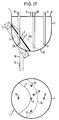
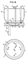
- FIGS. 17 and 18 show valve 1 through which gas flows, as has already been explained with reference to FIGS. 15 and 16.
- a gas-sealable filler pipe 28 is guided downwards from above through the upper side 8 of the pressure vessel 7 so that it projects into the magnetic liquid 3 in the horizontal basic position of the magnet 9.
- the filler pipe 28 is connected to a pump system (not shown) and enables the valve 1 to function continuously.
- a pump system not shown
- one, two or three inlet pipes are sealed.
- reusable valves are characterized in that they manage with a single pressure vessel, since the magnetic liquid is drawn into a strong magnetic field, so that certain inlet or outlet pipes can be opened or closed.
- reusable valves can also be created by several of the valves described above, which are connected to one another and switched via corresponding drill lines.
- a potentiometer can be arranged in front of each switch 12, 21, by means of which the current intensity applied to the electromagnets 9 and 19 can be changed continuously.
- the viscosity of the magnetic liquid 3 in turn changes, so that the viscosity of the magnetic liquid 3 is infinitely variable and more or less gas flows through the valve 1. This results in a continuously adjustable valve.
Landscapes
- Engineering & Computer Science (AREA)
- General Engineering & Computer Science (AREA)
- Mechanical Engineering (AREA)
- Magnetically Actuated Valves (AREA)
- Glass Compositions (AREA)
Applications Claiming Priority (2)
| Application Number | Priority Date | Filing Date | Title |
|---|---|---|---|
| DE29607363U DE29607363U1 (de) | 1996-04-23 | 1996-04-23 | Gasdurchströmtes Ventil |
| DE29607363U | 1996-04-23 |
Publications (3)
| Publication Number | Publication Date |
|---|---|
| EP0803673A2 true EP0803673A2 (fr) | 1997-10-29 |
| EP0803673A3 EP0803673A3 (fr) | 1998-05-20 |
| EP0803673B1 EP0803673B1 (fr) | 2002-06-26 |
Family
ID=8023002
Family Applications (1)
| Application Number | Title | Priority Date | Filing Date |
|---|---|---|---|
| EP97106432A Expired - Lifetime EP0803673B1 (fr) | 1996-04-23 | 1997-04-18 | Soupape à gaz |
Country Status (3)
| Country | Link |
|---|---|
| US (1) | US6044866A (fr) |
| EP (1) | EP0803673B1 (fr) |
| DE (2) | DE29607363U1 (fr) |
Cited By (1)
| Publication number | Priority date | Publication date | Assignee | Title |
|---|---|---|---|---|
| DE19816208B4 (de) * | 1998-04-09 | 2009-04-23 | Knorr-Bremse Systeme für Schienenfahrzeuge GmbH | Steuerventil |
Families Citing this family (10)
| Publication number | Priority date | Publication date | Assignee | Title |
|---|---|---|---|---|
| RU2240590C2 (ru) * | 2002-04-04 | 2004-11-20 | Институт техники, технологии и управления | Способ регулирования расхода жидких и газообразных сред |
| CA2382347A1 (fr) * | 2002-05-01 | 2003-11-01 | Autolog Inc. | Poste de classement avec zone de decision dynamique |
| US7670623B2 (en) * | 2002-05-31 | 2010-03-02 | Materials Modification, Inc. | Hemostatic composition |
| US7560160B2 (en) * | 2002-11-25 | 2009-07-14 | Materials Modification, Inc. | Multifunctional particulate material, fluid, and composition |
| US7007972B1 (en) | 2003-03-10 | 2006-03-07 | Materials Modification, Inc. | Method and airbag inflation apparatus employing magnetic fluid |
| US6982501B1 (en) | 2003-05-19 | 2006-01-03 | Materials Modification, Inc. | Magnetic fluid power generator device and method for generating power |
| US7200956B1 (en) | 2003-07-23 | 2007-04-10 | Materials Modification, Inc. | Magnetic fluid cushioning device for a footwear or shoe |
| US7448389B1 (en) | 2003-10-10 | 2008-11-11 | Materials Modification, Inc. | Method and kit for inducing hypoxia in tumors through the use of a magnetic fluid |
| WO2006113073A1 (fr) * | 2005-04-12 | 2006-10-26 | E. I. Du Pont De Nemours And Company | Systeme permettant de peser de maniere precise des solides et mecanisme de commande associe |
| CA2840172A1 (fr) * | 2010-06-23 | 2011-12-29 | The Greenward Company L.L.C. | Enveloppe magnetique appliquee de regulation d'ecoulement |
Family Cites Families (18)
| Publication number | Priority date | Publication date | Assignee | Title |
|---|---|---|---|---|
| US2670749A (en) * | 1949-07-21 | 1954-03-02 | Hanovia Chemical & Mfg Co | Magnetic valve |
| US3010471A (en) * | 1959-12-21 | 1961-11-28 | Ibm | Valve for magnetic fluids |
| US3417771A (en) * | 1965-09-24 | 1968-12-24 | Ernst Hans | Flow control apparatus for fluent magnetic materials |
| US3448751A (en) * | 1965-10-08 | 1969-06-10 | Norco Products Inc | Magnetic fluid pressure control |
| US3406704A (en) * | 1966-01-21 | 1968-10-22 | Wheelabrator Corp | Flow regulating valve for magnetic particles |
| US3701357A (en) * | 1968-09-30 | 1972-10-31 | Asea Ab | Electromagnetic valve means for tapping molten metal |
| US3982722A (en) * | 1975-11-21 | 1976-09-28 | General Motors Corporation | Magnetic control valve |
| US3970112A (en) * | 1975-12-08 | 1976-07-20 | General Motors Corporation | Control valve |
| DE2718508C3 (de) * | 1977-04-26 | 1980-12-04 | Nautschno-Issledovatelskaja Laboratorija Fiziko-Chimitscheskoj Mechaniki Materialov I Technologitscheskich Processov, Moskau | Verfahren zur Dosierung von Schüttgütern und Arbeitsorgan für eine entsprechende Dosiervorrichtung |
| DE2758072A1 (de) * | 1977-12-24 | 1979-07-05 | Teves Gmbh Alfred | Magnetventil |
| DE2839774A1 (de) * | 1978-09-13 | 1980-03-27 | Yoram Prof Dr Med Palti | Vorrichtung zur einstellung des durchflussquerschnitts eines ventils |
| JPS58672A (ja) * | 1981-06-25 | 1983-01-05 | Kiyuubitsuku Eng:Kk | 安全弁装置 |
| US4463502A (en) * | 1982-03-08 | 1984-08-07 | Fitzgerald Thomas J | Magnetic distributor-downcomer for fluidized beds and magnetic valve to control the flow of solids |
| US5075021A (en) * | 1989-09-29 | 1991-12-24 | Carlson J David | Optically transparent electrorheological fluids |
| US5032308A (en) * | 1989-11-07 | 1991-07-16 | The Dow Chemical Company | Layered mixed metal hydroxides in electrorheological fluids |
| MX170398B (es) * | 1989-11-14 | 1993-08-19 | Hylsa Sa | Metodo y aparato mejorados para regular el flujo de solidos ferromagneticos particulados |
| DE4100166A1 (de) * | 1991-01-05 | 1992-07-09 | Freudenberg Carl Fa | Druckregulierendes ent- und belueftungsventil |
| US5362027A (en) * | 1993-11-12 | 1994-11-08 | Electronics, Incorporated | Flow regulating valve for magnetic particles |
-
1996
- 1996-04-23 DE DE29607363U patent/DE29607363U1/de not_active Expired - Lifetime
-
1997
- 1997-04-18 EP EP97106432A patent/EP0803673B1/fr not_active Expired - Lifetime
- 1997-04-18 US US08/839,809 patent/US6044866A/en not_active Expired - Fee Related
- 1997-04-18 DE DE59707585T patent/DE59707585D1/de not_active Expired - Fee Related
Cited By (1)
| Publication number | Priority date | Publication date | Assignee | Title |
|---|---|---|---|---|
| DE19816208B4 (de) * | 1998-04-09 | 2009-04-23 | Knorr-Bremse Systeme für Schienenfahrzeuge GmbH | Steuerventil |
Also Published As
| Publication number | Publication date |
|---|---|
| US6044866A (en) | 2000-04-04 |
| EP0803673B1 (fr) | 2002-06-26 |
| EP0803673A3 (fr) | 1998-05-20 |
| DE29607363U1 (de) | 1996-08-22 |
| DE59707585D1 (de) | 2002-08-01 |
Similar Documents
| Publication | Publication Date | Title |
|---|---|---|
| DE69327329T2 (de) | Reibungsarmer magnetschalter und ventil | |
| EP0803673B1 (fr) | Soupape à gaz | |
| DE2737675A1 (de) | Umschaltventil mit magnetventilsteuerung | |
| EP2147219A1 (fr) | Dispositif de blocage avec liquide à champ réglable | |
| EP0402559A2 (fr) | Vanne de distribution | |
| EP1052441B1 (fr) | Soupape électromagnétique | |
| DE2424978A1 (de) | Rohrunterbrecher, insbesondere fuer hauswasserleitungen | |
| DE102009035444B4 (de) | Magnetventil und Verfahren zum Betreiben eines Magnetventils | |
| DE2510368A1 (de) | Einhebelsteuerung fuer kupplungen von wasser- und landfahrzeugen | |
| EP0638154B1 (fr) | Soupape pour la regulation du debit d'un fluide s'ecoulant sous pression | |
| DE2839774A1 (de) | Vorrichtung zur einstellung des durchflussquerschnitts eines ventils | |
| DE60121575T2 (de) | Hahn mit sekundärer öffnung | |
| DE602005004269T2 (de) | Ventil mit magnetischer steuereinheit | |
| EP0112977A1 (fr) | Organe d'arrêt pour fluides agressifs | |
| DE3027351A1 (de) | Magnetischer antriebsmechanismus und magnetisch betaetigte durchflussventile | |
| EP2000714A2 (fr) | Ensemble de soupapes à liquides | |
| DE69311014T2 (de) | Beschichtungsdüse | |
| DE60121156T2 (de) | Magnetisch steuerbares ventil | |
| DE643583C (de) | Kanalisationsanlage zum Abfuehren von Haushalts- und Industrieabfaellen mittels Unterdruckes | |
| WO2019007796A1 (fr) | Soupape | |
| WO2019068278A1 (fr) | Actionneur magnéto-rhéologique pourvu d'un système de fermeture | |
| DE3247323A1 (de) | Rohrtrenner | |
| EP1101032B1 (fr) | Dispositif de traitement magnetique | |
| DE102018003658A1 (de) | Prozesskomponente | |
| DE3902877C2 (fr) |
Legal Events
| Date | Code | Title | Description |
|---|---|---|---|
| PUAI | Public reference made under article 153(3) epc to a published international application that has entered the european phase |
Free format text: ORIGINAL CODE: 0009012 |
|
| AK | Designated contracting states |
Kind code of ref document: A2 Designated state(s): DE FR GB IT |
|
| PUAL | Search report despatched |
Free format text: ORIGINAL CODE: 0009013 |
|
| AK | Designated contracting states |
Kind code of ref document: A3 Designated state(s): DE FR GB IT |
|
| 17P | Request for examination filed |
Effective date: 19981116 |
|
| 17Q | First examination report despatched |
Effective date: 20001215 |
|
| GRAG | Despatch of communication of intention to grant |
Free format text: ORIGINAL CODE: EPIDOS AGRA |
|
| GRAG | Despatch of communication of intention to grant |
Free format text: ORIGINAL CODE: EPIDOS AGRA |
|
| GRAH | Despatch of communication of intention to grant a patent |
Free format text: ORIGINAL CODE: EPIDOS IGRA |
|
| GRAH | Despatch of communication of intention to grant a patent |
Free format text: ORIGINAL CODE: EPIDOS IGRA |
|
| GRAA | (expected) grant |
Free format text: ORIGINAL CODE: 0009210 |
|
| AK | Designated contracting states |
Kind code of ref document: B1 Designated state(s): DE FR GB IT |
|
| REG | Reference to a national code |
Ref country code: GB Ref legal event code: FG4D Free format text: NOT ENGLISH |
|
| REF | Corresponds to: |
Ref document number: 59707585 Country of ref document: DE Date of ref document: 20020801 |
|
| GBT | Gb: translation of ep patent filed (gb section 77(6)(a)/1977) |
Effective date: 20020827 |
|
| ET | Fr: translation filed | ||
| PLBE | No opposition filed within time limit |
Free format text: ORIGINAL CODE: 0009261 |
|
| STAA | Information on the status of an ep patent application or granted ep patent |
Free format text: STATUS: NO OPPOSITION FILED WITHIN TIME LIMIT |
|
| 26N | No opposition filed |
Effective date: 20030327 |
|
| PGFP | Annual fee paid to national office [announced via postgrant information from national office to epo] |
Ref country code: DE Payment date: 20050525 Year of fee payment: 9 |
|
| PGFP | Annual fee paid to national office [announced via postgrant information from national office to epo] |
Ref country code: FR Payment date: 20060410 Year of fee payment: 10 |
|
| PGFP | Annual fee paid to national office [announced via postgrant information from national office to epo] |
Ref country code: GB Payment date: 20060412 Year of fee payment: 10 |
|
| PGFP | Annual fee paid to national office [announced via postgrant information from national office to epo] |
Ref country code: IT Payment date: 20060430 Year of fee payment: 10 |
|
| PG25 | Lapsed in a contracting state [announced via postgrant information from national office to epo] |
Ref country code: DE Free format text: LAPSE BECAUSE OF NON-PAYMENT OF DUE FEES Effective date: 20061101 |
|
| GBPC | Gb: european patent ceased through non-payment of renewal fee |
Effective date: 20070418 |
|
| PG25 | Lapsed in a contracting state [announced via postgrant information from national office to epo] |
Ref country code: GB Free format text: LAPSE BECAUSE OF NON-PAYMENT OF DUE FEES Effective date: 20070418 |
|
| PG25 | Lapsed in a contracting state [announced via postgrant information from national office to epo] |
Ref country code: FR Free format text: LAPSE BECAUSE OF NON-PAYMENT OF DUE FEES Effective date: 20070430 |
|
| PG25 | Lapsed in a contracting state [announced via postgrant information from national office to epo] |
Ref country code: IT Free format text: LAPSE BECAUSE OF NON-PAYMENT OF DUE FEES Effective date: 20070418 |