EP0803657B1 - Reversing bearing device for double reversing propeller - Google Patents
Reversing bearing device for double reversing propeller Download PDFInfo
- Publication number
- EP0803657B1 EP0803657B1 EP95930041A EP95930041A EP0803657B1 EP 0803657 B1 EP0803657 B1 EP 0803657B1 EP 95930041 A EP95930041 A EP 95930041A EP 95930041 A EP95930041 A EP 95930041A EP 0803657 B1 EP0803657 B1 EP 0803657B1
- Authority
- EP
- European Patent Office
- Prior art keywords
- inner shaft
- oil
- contra
- oil feed
- bearing
- Prior art date
- Legal status (The legal status is an assumption and is not a legal conclusion. Google has not performed a legal analysis and makes no representation as to the accuracy of the status listed.)
- Expired - Lifetime
Links
Images


Classifications
-
- F—MECHANICAL ENGINEERING; LIGHTING; HEATING; WEAPONS; BLASTING
- F16—ENGINEERING ELEMENTS AND UNITS; GENERAL MEASURES FOR PRODUCING AND MAINTAINING EFFECTIVE FUNCTIONING OF MACHINES OR INSTALLATIONS; THERMAL INSULATION IN GENERAL
- F16C—SHAFTS; FLEXIBLE SHAFTS; ELEMENTS OR CRANKSHAFT MECHANISMS; ROTARY BODIES OTHER THAN GEARING ELEMENTS; BEARINGS
- F16C32/00—Bearings not otherwise provided for
- F16C32/06—Bearings not otherwise provided for with moving member supported by a fluid cushion formed, at least to a large extent, otherwise than by movement of the shaft, e.g. hydrostatic air-cushion bearings
- F16C32/0629—Bearings not otherwise provided for with moving member supported by a fluid cushion formed, at least to a large extent, otherwise than by movement of the shaft, e.g. hydrostatic air-cushion bearings supported by a liquid cushion, e.g. oil cushion
- F16C32/064—Bearings not otherwise provided for with moving member supported by a fluid cushion formed, at least to a large extent, otherwise than by movement of the shaft, e.g. hydrostatic air-cushion bearings supported by a liquid cushion, e.g. oil cushion the liquid being supplied under pressure
- F16C32/0651—Details of the bearing area per se
-
- B—PERFORMING OPERATIONS; TRANSPORTING
- B63—SHIPS OR OTHER WATERBORNE VESSELS; RELATED EQUIPMENT
- B63H—MARINE PROPULSION OR STEERING
- B63H21/00—Use of propulsion power plant or units on vessels
- B63H21/38—Apparatus or methods specially adapted for use on marine vessels, for handling power plant or unit liquids, e.g. lubricants, coolants, fuels or the like
- B63H21/386—Apparatus or methods specially adapted for use on marine vessels, for handling power plant or unit liquids, e.g. lubricants, coolants, fuels or the like for handling lubrication liquids
-
- B—PERFORMING OPERATIONS; TRANSPORTING
- B63—SHIPS OR OTHER WATERBORNE VESSELS; RELATED EQUIPMENT
- B63H—MARINE PROPULSION OR STEERING
- B63H23/00—Transmitting power from propulsion power plant to propulsive elements
- B63H23/32—Other parts
- B63H23/321—Bearings or seals specially adapted for propeller shafts
-
- B—PERFORMING OPERATIONS; TRANSPORTING
- B63—SHIPS OR OTHER WATERBORNE VESSELS; RELATED EQUIPMENT
- B63H—MARINE PROPULSION OR STEERING
- B63H5/00—Arrangements on vessels of propulsion elements directly acting on water
- B63H5/07—Arrangements on vessels of propulsion elements directly acting on water of propellers
- B63H5/08—Arrangements on vessels of propulsion elements directly acting on water of propellers of more than one propeller
- B63H5/10—Arrangements on vessels of propulsion elements directly acting on water of propellers of more than one propeller of coaxial type, e.g. of counter-rotative type
-
- F—MECHANICAL ENGINEERING; LIGHTING; HEATING; WEAPONS; BLASTING
- F16—ENGINEERING ELEMENTS AND UNITS; GENERAL MEASURES FOR PRODUCING AND MAINTAINING EFFECTIVE FUNCTIONING OF MACHINES OR INSTALLATIONS; THERMAL INSULATION IN GENERAL
- F16C—SHAFTS; FLEXIBLE SHAFTS; ELEMENTS OR CRANKSHAFT MECHANISMS; ROTARY BODIES OTHER THAN GEARING ELEMENTS; BEARINGS
- F16C17/00—Sliding-contact bearings for exclusively rotary movement
- F16C17/02—Sliding-contact bearings for exclusively rotary movement for radial load only
- F16C17/028—Sliding-contact bearings for exclusively rotary movement for radial load only with fixed wedges to generate hydrodynamic pressure, e.g. multi-lobe bearings
-
- F—MECHANICAL ENGINEERING; LIGHTING; HEATING; WEAPONS; BLASTING
- F16—ENGINEERING ELEMENTS AND UNITS; GENERAL MEASURES FOR PRODUCING AND MAINTAINING EFFECTIVE FUNCTIONING OF MACHINES OR INSTALLATIONS; THERMAL INSULATION IN GENERAL
- F16C—SHAFTS; FLEXIBLE SHAFTS; ELEMENTS OR CRANKSHAFT MECHANISMS; ROTARY BODIES OTHER THAN GEARING ELEMENTS; BEARINGS
- F16C33/00—Parts of bearings; Special methods for making bearings or parts thereof
- F16C33/02—Parts of sliding-contact bearings
- F16C33/04—Brasses; Bushes; Linings
- F16C33/06—Sliding surface mainly made of metal
- F16C33/10—Construction relative to lubrication
- F16C33/1025—Construction relative to lubrication with liquid, e.g. oil, as lubricant
- F16C33/106—Details of distribution or circulation inside the bearings, e.g. details of the bearing surfaces to affect flow or pressure of the liquid
- F16C33/1065—Grooves on a bearing surface for distributing or collecting the liquid
-
- F—MECHANICAL ENGINEERING; LIGHTING; HEATING; WEAPONS; BLASTING
- F16—ENGINEERING ELEMENTS AND UNITS; GENERAL MEASURES FOR PRODUCING AND MAINTAINING EFFECTIVE FUNCTIONING OF MACHINES OR INSTALLATIONS; THERMAL INSULATION IN GENERAL
- F16C—SHAFTS; FLEXIBLE SHAFTS; ELEMENTS OR CRANKSHAFT MECHANISMS; ROTARY BODIES OTHER THAN GEARING ELEMENTS; BEARINGS
- F16C33/00—Parts of bearings; Special methods for making bearings or parts thereof
- F16C33/02—Parts of sliding-contact bearings
- F16C33/04—Brasses; Bushes; Linings
- F16C33/06—Sliding surface mainly made of metal
- F16C33/10—Construction relative to lubrication
- F16C33/1025—Construction relative to lubrication with liquid, e.g. oil, as lubricant
- F16C33/106—Details of distribution or circulation inside the bearings, e.g. details of the bearing surfaces to affect flow or pressure of the liquid
- F16C33/1075—Wedges, e.g. ramps or lobes, for generating pressure
-
- B—PERFORMING OPERATIONS; TRANSPORTING
- B63—SHIPS OR OTHER WATERBORNE VESSELS; RELATED EQUIPMENT
- B63H—MARINE PROPULSION OR STEERING
- B63H5/00—Arrangements on vessels of propulsion elements directly acting on water
- B63H5/07—Arrangements on vessels of propulsion elements directly acting on water of propellers
- B63H5/08—Arrangements on vessels of propulsion elements directly acting on water of propellers of more than one propeller
- B63H5/10—Arrangements on vessels of propulsion elements directly acting on water of propellers of more than one propeller of coaxial type, e.g. of counter-rotative type
- B63H2005/106—Arrangements on vessels of propulsion elements directly acting on water of propellers of more than one propeller of coaxial type, e.g. of counter-rotative type with drive shafts of second or further propellers co-axially passing through hub of first propeller, e.g. counter-rotating tandem propellers with co-axial drive shafts
-
- B—PERFORMING OPERATIONS; TRANSPORTING
- B63—SHIPS OR OTHER WATERBORNE VESSELS; RELATED EQUIPMENT
- B63H—MARINE PROPULSION OR STEERING
- B63H23/00—Transmitting power from propulsion power plant to propulsive elements
- B63H23/32—Other parts
- B63H23/321—Bearings or seals specially adapted for propeller shafts
- B63H2023/323—Bearings for coaxial propeller shafts, e.g. for driving propellers of the counter-rotative type
-
- F—MECHANICAL ENGINEERING; LIGHTING; HEATING; WEAPONS; BLASTING
- F16—ENGINEERING ELEMENTS AND UNITS; GENERAL MEASURES FOR PRODUCING AND MAINTAINING EFFECTIVE FUNCTIONING OF MACHINES OR INSTALLATIONS; THERMAL INSULATION IN GENERAL
- F16C—SHAFTS; FLEXIBLE SHAFTS; ELEMENTS OR CRANKSHAFT MECHANISMS; ROTARY BODIES OTHER THAN GEARING ELEMENTS; BEARINGS
- F16C2326/00—Articles relating to transporting
- F16C2326/30—Ships, e.g. propelling shafts and bearings therefor
Definitions
- the present invention relates to a contra-rotating bearing device for a contra-rotating propeller.
- a contra-rotating propeller in which an outer shaft having a front propeller and an inner shaft fitted in the outer shaft and having a rear propeller are caused to rotate in mutually opposite directions in order to effectively utilize propeller propulsion energy.
- the contra-rotating propeller has been employed in order to enhance the propulsion efficiency of a ship propulsion system.
- FIG. 9 is a partial broken side view showing a contra-rotating propeller according to the prior art
- Fig. 10 is a sectional view taken along the line E - E shown in Fig. 9.
- a contra-rotating propeller 100 includes a hollow outer shaft 102 having a front propeller 101, an inner shaft 104 provided in the outer shaft 102 and having a rear propeller 103, and a main engine 105 for causing the outer shaft 102 and the inner shaft 104 to rotate in mutually opposite directions.
- the outer shaft 102 has a cylindrical shape, and is rotatably provided on a stern portion 106 of a hull Y through an outer shaft bearing 107 and an outer shaft seal 108.
- the inner shaft 104 is provided inside the outer shaft 102 through a contra-rotating bearing 109 and an inner shaft seal 110 so as to rotate in the opposite direction.
- the hull Y is provided with a lubrication oil supply system 111 for supplying lubrication oil to the outer shaft 102, the inner shaft 104, the outer shaft bearing 107 and the contra-rotating bearing 109.
- a rudder horn 112 and a rudder plate 113 are opposed to the front propeller 101 and the rear propeller 103.
- an ordinary journal bearing mechanism can be employed as the outer shaft bearing 107 provided between the outer shaft 102 and the stern portion 106.
- the contra-rotating bearing 109 which supports the inner shaft 104 that rotates in the outer shaft 102 in the opposite direction, particularly as shown in Fig.
- a floating bush 114 is provided between the outer shaft 102 and the inner shaft 104 as shown in a sectional view (Fig. 12). And, the floating bush 114 is almost kept stationary between both shafts 102 and 104 so that an oil film is formed between the floating bush 114 and each of the inner shaft 104 and outer shaft 102 to form a contra-rotating bearing.
- an oil film which can display the bearing function can be formed during ordinary operation, while the oil film is formed with difficulty during low-speed operation when entering and leaving a port so that metallic contact is sometimes caused on the bearing surface.
- the inner shaft 104 is bent easily by a cantilever support of the rear propeller 103 so that local contact may be caused on the rear end of the bearing.
- a tapered land (not shown) is formed on the inner face of the contra-rotating bearing 109 which supports the inner shaft 104, and a dynamic pressure is generated by a tapered portion of the tapered land to form an oil film so that the inner shaft 104 is lifted up.
- a load carrying capacity generated by the dynamic pressure is small when causing the main engine 105 to start or rotate at a low speed. Consequently, the oil film becomes thinner.
- the inner shaft 104 and the contra-rotating bearing 109 metallically comes in contact with each other on the bearing surface so that the contra-rotating bearing 109 is seized.
- Figure 13 shows a contra-rotating bearing device for a contra-rotating propeller comprising an inner shaft for driving a rear propeller and an outer shaft for driving a front propeller, both shafts rotating in mutually opposite directions, wherein a hollow portion is provided on the core of the inner shaft to form an oil feed port, a plurality of oil feed holes which are connected with both of the outer peripheral face of the inner shaft within the range of the bearing surface of the inner shaft and the oil feed port are radially provided.
- a screw 117 having a small hole for orifice formation or capillary tube restriction is fitted in the oil feed hole 116 to eject high-pressure oil from the oil feed hole 116 toward the contra-rotating bearing surface between the inner shaft 104 and the outer shaft 102 or the contra-rotating bearing 109 so that a load carrying capacity is generated by a static pressure to lift up the inner shaft 104, thereby preventing the local contact of the inner shaft 104.
- a contra-rotating bearing in which a plurality of oil feed holes 116 which are radially provided and connected with both of the outer peripheral face of the inner shaft within a range L of the bearing surface of the inner shaft 104 and the concentric hole 115 provided on the core of the inner shaft 104, and the oil feed holes 116 are arranged in a plurality of lines in the longitudinal direction of the inner shaft as shown in sectional views of Figs. 14 (a) and (b).
- the contra-rotating bearing 109 of the outer shaft 102 is circular bearing. For this reason, when the inner shaft 104 and the outer shaft 102 rotate in mutually opposite directions at equal speeds as described above, the circular bearing does not generate a load carrying capacity by the dynamic pressure of the lubrication oil theoretically.
- the present invention has been made in order to provide a contra-rotating bearing device for a contra-rotating propeller wherein a sufficient oil film is formed on the bearing surface of a contra-rotating bearing which supports an inner shaft in the contra-rotating propeller so that an improved bearing function can be displayed.
- the present invention provides a contra-rotating bearing device for a contra-rotating propeller comprising an inner shaft for driving a rear propeller and an outer shaft for driving a front propeller, both shafts rotating in mutually opposite directions, wherein a hollow portion is provided on the core of the inner shaft to form an oil feed port, a plurality of oil feed holes which are connected with both of the outer peripheral face of the inner shaft within the range of the bearing surface of the inner shaft and the oil feed port are radially provided, characterised in that oil grooves, each of which includes an inner shaft surface side opening portion of the oil feed hole, are provided on the outer peripheral face of the inner shaft.
- a plurality of said oil feed holes may be radially provided in a line.
- a plurality of said oil feed holes are radially provided, the oil feed holes being axially provided in a plurality of lines, and said oil grooves are circumferential or axial.
- Such oil feed holes may be offset circumferentially.
- the cross sectional area of a said oil groove is formed so as to be decreased from the inner shaft surface side opening portion of the oil feed hole to ends thereof.
- a contra-rotating bearing device for a contra-rotating propeller which can lubricate the contra-rotating bearing by using a small number of oil feed holes without reducing the strength of the inner shaft; a contra-rotating bearing device for a contra-rotating propeller which can supply lubrication oil having a pressure which is necessary within the range of the bearing surface of the inner shaft by simple working; a contra-rotating bearing device for a contra-rotating propeller which can particularly give a load carrying capacity to the contra-rotating bearing during uniform contra-rotation in which an inner shaft and an outer shaft rotate in mutually opposite directions at almost equal speeds, or in the state close thereto; a contra-rotating bearing device for a contra-rotating propeller to surely keep a load carrying capacity by supporting the inner shaft with only the load carrying capacity generated by the dynamic pressure of the lubrication oil in the high rotation area of an engine and by increasing an oil feeding pressure to add a static pressure in a low rotation area in which it is hard to generate the sufficient
- lubrication oil fed through the oil feed port of the inner shaft is supplied to the bearing surface through a plurality of the oil feed holes which are provided radially within the range of the bearing surface of the inner shaft and connected with the outer peripheral face of the inner shaft. Therefore, the lubrication oil having a pressure which is necessary for almost the whole range of the bearing surface is supplied by the oil grooves provided on the outer peripheral face of the inner shaft including the inner shaft surface side opening portions of the oil feed holes so that an oil film is formed to support the inner shaft.
- the function of the contra-rotating bearing for a contra-rotating propeller for causing both shafts to rotate in mutually opposite directions can be obtained.
- the contra-rotating bearing which can display the bearing function can be formed with a small number of oil feed holes. Consequently, a reduction in strength of the shaft can be prevented and processing can be performed easily to decrease working manhour. Thus, the manufacturing time and the manufacturing costs for the contra-rotating bearing can be reduced greatly.
- the plurality of oil feed holes are radially provided in a line, and axial oil grooves each of which includes an inner shaft surface side opening portion of the oil feed hole are provided on the outer peripheral face of the inner shaft. Consequently, the lubrication oil fed through the oil feed port is supplied to the bearing surface through the oil feed holes which are radially provided in a line within the range of the bearing surface of the inner shaft and connected with the outer peripheral face of the inner shaft. Therefore, the lubrication oil having a pressure which is necessary for almost the whole range of the bearing surface is supplied by the axial oil grooves provided on the outer peripheral face of the inner shaft including the inner shaft surface side opening portions of the oil feed holes so that the inner shaft can be supported.
- the plurality of oil feed holes are radially provided, the oil feed hole being axially provided in a plurality of lines, and circumferential oil grooves or axial oil grooves each of which includes an inner shaft surface side opening portion of the oil feed hole are provided on the outer peripheral face of the inner shaft. Consequently, the lubrication oil fed through the oil feed port is supplied to the bearing surface through the oil feed holes which are radially provided within the range of the bearing surface of the inner shaft and axially provided in a plurality of lines, and connected with the outer peripheral face of the inner shaft.
- the lubrication oil having a pressure which is necessary for almost the whole range of the bearing surface is supplied by the circumferential or axial oil grooves which are provided on the outer peripheral face of the inner shaft including the inner shaft surface side opening portions of the oil feed holes so that the inner shaft can be supported.
- the oil feed holes are axially provided in a plurality of lines and offset circumferentially, the lubrication oil having a necessary pressure is easily supplied efficiently to almost the whole range of the bearing surface through the oil feed holes.
- the inner shaft can be supported.
- the cross-sectional area of the oil groove When the cross-sectional area of the oil groove is formed so as to be decreased from the inner shaft surface side opening portion of the oil feed hole to ends thereof, the cross-sectional area of the oil groove can be formed so as to be decreased from the inner shaft surface side opening portion of the oil feed hole to ends thereof. Accordingly, the pressure of the lubrication oil can be optimized within the range of the bearing surface by changing the cross-sectional area of the oil groove.
- a contra-rotating bearing device which generates an oil pressure according to a load within the range of the bearing surface can be formed.
- an outer shaft 1 for driving a front propeller of the contra-rotating propeller and an inner shaft 2 for driving a rear propeller are provided almost concentrically so as to rotate in mutually opposite directions.
- the outer shaft 1 is supported by a journal bearing provided on a hull, which is not shown.
- the inner shaft 2 is supported by the contra-rotating bearing device T1 formed in the outer shaft 1.
- a hollow portion is provided on the core of the inner shaft 2 to form an oil feed port 3, and a plurality of oil feed holes 4 which are connected with both of the outer peripheral face of the inner shaft and the oil feed port 3 are provided within a range L of a bearing surface.
- the oil feed holes 4 are provided in a line on the rear end side within the range L of the bearing surface, that is, the after side having a greater load on the propeller side.
- eight oil feed holes 4 are radially provided.
- Axial oil grooves 5 are provided within the range L of the bearing surface on the outer peripheral face of the inner shaft including an inner shaft surface side opening portions 4a of the oil feed holes 4. According to the present embodiment, it is preferable that the number of the oil feed holes 4 should be three or more.
- the oil grooves 5 are formed from a plurality of oil feed holes 4 toward the fore side in the axial direction, and has a structure in which lubrication oil fed from the oil feed holes 4 generates a predetermined oil pressure that is necessary for the range L of the bearing surface along the oil groove 5.
- the oil groove 5 can be easily processed because it is formed on the surface of the inner shaft 2.
- the oil groove 5 may be a deep groove in (a) or a groove having a shallow oil reservoir in (b). In other words, it is sufficient that the oil groove 5 can generate a predetermined oil pressure within the range L of the bearing surface.
- the cross-sectional area of an oil groove is formed so as to be decreased from the inner shaft surface side opening portion the oil feed hole to ends thereof.
- the range of the bearing surface (bearing length) is expressed by L
- the outer diameter of the inner shaft is expressed by D
- a radius clearance is expressed by Cr
- the axial length of the oil groove is expressed by v
- a width is expressed by w
- Eight oil feed holes 4 are provided in a line in positions apart from the center of the range L of the bearing surface backward by a predetermined distance of L1.
- An oil groove 5 having an axial length v and a width w is provided around an inner shaft surface side opening portion 4a of the oil feed hole 4.
- the predetermined distance L1 should be L/6 to L/4
- the width w of the oil groove 5 should be ⁇ D/32
- the axial length v should be 1w to 2w.
- the depth of the oil groove 5 should be three to five times as much as the radius clearance Cr. According to general documents, a pressure drop can be ignored when the depth of the oil groove 5 is ten times as much as the radius clearance Cr or more. Consequently, it is supposed that a great change in the pressure is not caused in the oil groove 5 even through the depth of the oil groove 5 is three to five times as much as the radius clearance Cr or more. Therefore, if the position of the oil groove 5 is set, the pressure of the oil groove 5 is not changed greatly even though the position of the opening portion 4a of the oil feed hole 4 is changed axially. Thus, bearing performance is not affected greatly.
- the oil groove 5 according to the first embodiment may be tapered in such a manner that it gradually becomes shallower from the position where the oil feed hole 4 is provided toward an end 5a, that is, an axial sectional area is decreased from the inner shaft surface side opening portion of the oil feed hole 4 to the end thereof.
- the oil feed hole 4 is provided in a position where a high oil pressure is necessary within the range L of the bearing surface to reduce the oil pressure in a position apart from the oil feed hole 4 so that the optimum pressure of the lubrication oil can be obtained over the range L of the bearing surface.
- a groove width, a groove depth or both of them can be decreased.
- the contra-rotating bearing device T1 for a contra-rotating propeller having the above-mentioned structure according to the first embodiment functions as a contra-rotating bearing which supports the inner shaft 2 in the following manner.
- the oil fed from the oil feed port 3 of the inner shaft 2 is supplied to the inner shaft surface through the oil feed hole 4 and flows into the range L of the bearing surface along the oil groove 5.
- the contra-rotating bearing device T1 functions to generate a predetermined oil pressure within the range L of the bearing surface so that an oil film is formed and the inner shaft 2 is supported.
- the contra-rotating bearing device T1 can be formed by the oil feed holes 4 provided on the inner shaft 2 in a line. Consequently, a small number of oil feed holes 4 are provided on the inner shaft 2 so that the contra-rotating bearing device T1 can be formed without reducing an axial strength.
- a contra-rotating bearing device T2 according to the second embodiment will be described below with reference to a side sectional view of Fig. 5.
- the oil feed hole 4 according to the first embodiment is provided in almost the central portion within a range L of a bearing surface. Therefore, the same structures have the same reference numerals as in the first embodiment and their description will be omitted.
- the oil feed hole 4 according to the second embodiment is provided in almost the central portion within the range L of the bearing surface, and an oil groove 5 is provided from the oil feed hole 4 toward the fore and after sides within the range L of the bearing surface.
- the width or depth of the oil groove 5 provided from an opening portion 4a of the oil feed hole 4 toward the fore side and the width or depth of the oil groove 5 provided from the opening portion 4a toward the after side are set to optimum values so that an oil pressure within the range L of the bearing surface can be controlled to obtain an optimum function as the contra-rotating bearing device T2. Also in the second embodiment, the same functions and effects as in the first embodiment can be obtained.
- a contra-rotating bearing device T3 according to the third embodiment will be described below with reference to a side sectional view in figs. 6 (a) and (b) and a sectional view taken along the line B - B in Figs. 6 (a) and (b).
- the same structures have the same reference numerals as in the first embodiment and their description will be omitted.
- oil feed holes 4 are axially provided in a plurality of lines, that is, three lines within a range L of a bearing surface, each line having two oil feed holes 4 as shown.
- the oil feed holes 4 are provided in positions where the phases of the first and the second lines are shifted (hereinafter referred to as "offset") by 90 degrees in the circumferential direction.
- the oil feed holes 4 are provided in positions where the second and third lines are offset by 90 degrees.
- Oil grooves 6 are provided in the circumferential direction within the range L of the bearing surface including inner shaft surface side opening portions 4a of the oil feed holes 4.
- the surface of an inner shaft 2 is processed. Consequently, processing can be easily performed in the same manner as in the first embodiment.
- the contra-rotating bearing device T3 for a contra-rotating propeller having the above-mentioned structure according to the third embodiment functions to support the inner shaft 2 in the following manner.
- oil fed from an oil feed port 3 of the inner shaft 2 is supplied from the oil feed holes 4 which are axially provided in a plurality of lines into the range L of the bearing surface, and a predetermined oil pressure is generated on the surface of the inner shaft 2 to form an oil film.
- the contra-rotating bearing function can be displayed. Since the propeller is provided on the after side, a load is usually great on the after side. Therefore, it is sufficient that the oil pressure is generated within the range L of the bearing surface corresponding to the load therein by setting the diameters of the oil feed holes 4, the width of the oil groove 6, the depth of the oil groove 6 and the like on the after and fore sides to optimum values.
- Other functions and effects are the same as in the first embodiment.
- a contra-rotating bearing device T4 according to the fourth embodiment will be described below with reference to a side sectional view of Fig. 7.
- the number of oil feed holes 4 which are axially provided in the third embodiment is increased and the oil feed holes 4 are offset by a predetermined amount.
- the same structures have the same reference numerals as in the third embodiment and their description will be omitted.
- the oil feed holes 4 are axially provided in a plurality of lines, that is, five lines within a range L of a bearing surface, each line having two oil feed holes 4 as shown.
- the oil feed holes 4 are provided in such a manner that the first and the second lines are shifted in the circumferential direction, that is offset, by 45 degrees.
- the second and the third lines are also offset by 45 degrees, and the following lines are sequentially offset by 45 degrees.
- Oil grooves 6 are provided in the circumferential direction within the range L of the bearing surface including an inner shaft surface side opening portions 4a of the oil feed holes 4.
- the surface of an inner shaft 2 is processed. Consequently, processing can be easily performed.
- the contra-rotating bearing device T4 for a contra-rotating propeller having the above-mentioned structure according to the fourth embodiment functions in the same manner as the contra-rotating bearing device T3 for a contra-rotating propeller in the third embodiment described above.
- oil fed from an oil feed port 3 of the inner shaft 2 is supplied into the range L of the bearing surface through the oil feed holes 4 which are axially provided in a plurality of lines, and a predetermined oil pressure is operated on the surface of the inner shaft 2 to form an oil film.
- the contra-rotating bearing function can be displayed.
- the oil feed holes 4 are axially provided in more lines than in the third embodiment. Consequently, the oil pressure can be controlled corresponding to a load within the range L of the bearing surface.
- Other functions and effects are the same as in the third embodiment described above.
- a contra-rotating bearing device T5 according to the fifth embodiment will be described below with reference to a side sectional view of Fig. 8.
- a circumferential oil groove in the third embodiment is changed into an axial oil groove.
- oil feed holes 4 are axially provided in a plurality of lines, that is, three lines within a range L of a bearing surface, each line having two oil feed holes 4 in the same manner as in the third embodiment.
- the oil feed holes 4 are provided in positions where the first and the second lines are circumferentially offset by 90 degrees.
- the second and the third lines are also offset by 90 degrees.
- Oil grooves 5 are axially provided within the range L of the bearing surface including inner shaft surface side opening portions 4a of the oil feed holes 4.
- the contra-rotating bearing device T5 for a contra-rotating propeller having the above-mentioned structure according to the fifth embodiment functions in the same manner as the contra-rotating bearing device T3 in the third embodiment described above.
- oil fed from the oil feed port 3 of the inner shaft 2 is supplied into the range L of the bearing surface through the oil feed holes 4 which are axially provided in a plurality of lines, and a predetermined oil pressure is generated on the surface of the inner shaft 2 to form an oil film.
- the contra-rotating bearing function can be obtained.
- the oil pressure corresponding to a load within the range L of the bearing surface can be generated by setting the diameters of the oil feed holes 4, the width of the oil groove 5, the depth of the oil groove 5 and the like on the after and fore sides to optimum values in the same manner as in the third embodiment, or by making the tapered shape as shown in Fig. 4.
- a sufficient oil film is formed on the bearing surface which supports the inner shaft of the contra-rotating propeller so that an excellent bearing function can be obtained.
- the embodiments display the bearing function of a contra-rotating bearing when an inner shaft and an outer shaft rotate in mutually opposite directions at almost equal speeds, and are particularly suitable for a large-sized contra-rotating propeller of a ship or the like.
- An excellent bearing function can be obtained as a contra-rotating bearing which supports an inner shaft of a contra-rotating propeller in which the inner shaft and an outer shaft rotate in mutually opposite directions, which is useful for the general contra-rotating bearing device for supporting the inner shaft of the contra-rotating propeller, and more particularly suitable for a contra-rotating bearing device for a contra-rotating propeller of a ship which is provided with a large-sized contra-rotating propeller requiring a great load carrying capacity.
Abstract
Description
- The present invention relates to a contra-rotating bearing device for a contra-rotating propeller.
- Conventionally, a contra-rotating propeller has been known in which an outer shaft having a front propeller and an inner shaft fitted in the outer shaft and having a rear propeller are caused to rotate in mutually opposite directions in order to effectively utilize propeller propulsion energy. Recently, the contra-rotating propeller has been employed in order to enhance the propulsion efficiency of a ship propulsion system.
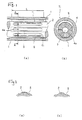
- For example, Fig. 9 is a partial broken side view showing a contra-rotating propeller according to the prior art, and Fig. 10 is a sectional view taken along the line E - E shown in Fig. 9. A contra-rotating
propeller 100 includes a hollowouter shaft 102 having afront propeller 101, aninner shaft 104 provided in theouter shaft 102 and having arear propeller 103, and amain engine 105 for causing theouter shaft 102 and theinner shaft 104 to rotate in mutually opposite directions. Theouter shaft 102 has a cylindrical shape, and is rotatably provided on astern portion 106 of a hull Y through an outer shaft bearing 107 and anouter shaft seal 108. Theinner shaft 104 is provided inside theouter shaft 102 through a contra-rotating bearing 109 and aninner shaft seal 110 so as to rotate in the opposite direction. The hull Y is provided with a lubrication oil supply system 111 for supplying lubrication oil to theouter shaft 102, theinner shaft 104, the outer shaft bearing 107 and the contra-rotating bearing 109. Arudder horn 112 and arudder plate 113 are opposed to thefront propeller 101 and therear propeller 103. - In the contra-rotating
propeller 100 having such a structure, an ordinary journal bearing mechanism can be employed as the outer shaft bearing 107 provided between theouter shaft 102 and thestern portion 106. In the contra-rotating bearing 109 which supports theinner shaft 104 that rotates in theouter shaft 102 in the opposite direction, particularly as shown in Fig. 10, however, in the case where theinner shaft 104 rotates clockwise and the contra-rotating bearing 109 such as a plain bearing which is fixed to theouter shaft 102 and the inner peripheral face thereof rotates counterclockwise, there is a possibility that lubrication oil cannot form an oil film between the outer peripheral face of theinner shaft 104 and the inner peripheral face of the contra-rotating bearing 109 if theouter shaft 102 and theinner shaft 104 rotate at almost equal speeds. For this reason, it becomes hard for theshafts inner shaft 104 and theouter shaft 102 rotate in mutually opposite directions at almost equal speeds as shown in a sectional view (Fig. 11) in which the contra-rotating bearing 109 is provided on the inner peripheral face of the outer shaft. Thus, there is a possibility that the ordinary bearing cannot display the bearing function. - For this reason, in some prior art bearings, a floating
bush 114 is provided between theouter shaft 102 and theinner shaft 104 as shown in a sectional view (Fig. 12). And, the floatingbush 114 is almost kept stationary between bothshafts bush 114 and each of theinner shaft 104 andouter shaft 102 to form a contra-rotating bearing. In case of a hydrodynamic bearing using the floatingbush 114, however, an oil film which can display the bearing function can be formed during ordinary operation, while the oil film is formed with difficulty during low-speed operation when entering and leaving a port so that metallic contact is sometimes caused on the bearing surface. Furthermore, theinner shaft 104 is bent easily by a cantilever support of therear propeller 103 so that local contact may be caused on the rear end of the bearing. - In some bearings, a tapered land (not shown) is formed on the inner face of the contra-rotating bearing 109 which supports the
inner shaft 104, and a dynamic pressure is generated by a tapered portion of the tapered land to form an oil film so that theinner shaft 104 is lifted up. Also in the case where the tapered land is provided, however, a load carrying capacity generated by the dynamic pressure is small when causing themain engine 105 to start or rotate at a low speed. Consequently, the oil film becomes thinner. Thus, there is a possibility that theinner shaft 104 and the contra-rotating bearing 109 metallically comes in contact with each other on the bearing surface so that the contra-rotating bearing 109 is seized. - The above mentioned problems with the prior art are solved to some extent by the contra-rotating bearing device disclosed in Japanese Examined Patent Publication No. 5-45479 entitled "STERN TUBE BEARING SYSTEM OF CONTRA-ROTATING PROPELLER". Figure 13 shows a sectional view of a hydrostatic bearing disclosed in that Patent Publication.
- Figure 13 shows a contra-rotating bearing device for a contra-rotating propeller comprising an inner shaft for driving a rear propeller and an outer shaft for driving a front propeller, both shafts rotating in mutually opposite directions, wherein a hollow portion is provided on the core of the inner shaft to form an oil feed port, a plurality of oil feed holes which are connected with both of the outer peripheral face of the inner shaft within the range of the bearing surface of the inner shaft and the oil feed port are radially provided.
- A
screw 117 having a small hole for orifice formation or capillary tube restriction is fitted in theoil feed hole 116 to eject high-pressure oil from theoil feed hole 116 toward the contra-rotating bearing surface between theinner shaft 104 and theouter shaft 102 or the contra-rotating bearing 109 so that a load carrying capacity is generated by a static pressure to lift up theinner shaft 104, thereby preventing the local contact of theinner shaft 104. In addition, a contra-rotating bearing has been disclosed in which a plurality ofoil feed holes 116 which are radially provided and connected with both of the outer peripheral face of the inner shaft within a range L of the bearing surface of theinner shaft 104 and theconcentric hole 115 provided on the core of theinner shaft 104, and theoil feed holes 116 are arranged in a plurality of lines in the longitudinal direction of the inner shaft as shown in sectional views of Figs. 14 (a) and (b). - In case of above-mentioned contra-rotating bearing, however, the contra-rotating bearing 109 of the
outer shaft 102 is circular bearing. For this reason, when theinner shaft 104 and theouter shaft 102 rotate in mutually opposite directions at equal speeds as described above, the circular bearing does not generate a load carrying capacity by the dynamic pressure of the lubrication oil theoretically. Consequently, in case of a high ratio of number of revolutions in which theinner shaft 104 and the outer shaft 102 (contrarotating bearing 109) rotate in mutually opposite directions at almost equal speeds, there is a possibility that an oil film is not formed but seizure is easily caused when the static pressure oil supply from the radialoil feed hole 116 is not performed due to blackout or the failure of an oil feeding pump of the lubrication oil supply system 111. - In case of the high ratio of number of revolutions, the load carrying capacity generated by the dynamic pressure is insufficient as described above. For this reason, it is necessary to supply the lubrication oil from the radial
oil feed hole 116 with a comparatively high static pressure. Consequently, the size of the lubrication oil supply system 111 becomes larger. Furthermore, a lot ofoil feed holes 116 are provided on theinner shaft 104 to form the static pressure bearing. For this reason, the strength of theinner shaft 104 is sometimes lowered. In such a case, it is necessary to increase an inner shaft diameter in order to maintain the strength of the inner shaft. Consequently, a weight is increased and the size of a propulsion unit becomes larger. - The present invention has been made in order to provide a contra-rotating bearing device for a contra-rotating propeller wherein a sufficient oil film is formed on the bearing surface of a contra-rotating bearing which supports an inner shaft in the contra-rotating propeller so that an improved bearing function can be displayed.
- The present invention provides a contra-rotating bearing device for a contra-rotating propeller comprising an inner shaft for driving a rear propeller and an outer shaft for driving a front propeller, both shafts rotating in mutually opposite directions, wherein a hollow portion is provided on the core of the inner shaft to form an oil feed port, a plurality of oil feed holes which are connected with both of the outer peripheral face of the inner shaft within the range of the bearing surface of the inner shaft and the oil feed port are radially provided, characterised in that oil grooves, each of which includes an inner shaft surface side opening portion of the oil feed hole, are provided on the outer peripheral face of the inner shaft.
- A plurality of said oil feed holes may be radially provided in a line.
- Optionally, a plurality of said oil feed holes are radially provided, the oil feed holes being axially provided in a plurality of lines, and said oil grooves are circumferential or axial. Such oil feed holes may be offset circumferentially.
- Preferably, the cross sectional area of a said oil groove is formed so as to be decreased from the inner shaft surface side opening portion of the oil feed hole to ends thereof.
- The embodiments hereinafter describe: a contra-rotating bearing device for a contra-rotating propeller which can lubricate the contra-rotating bearing by using a small number of oil feed holes without reducing the strength of the inner shaft; a contra-rotating bearing device for a contra-rotating propeller which can supply lubrication oil having a pressure which is necessary within the range of the bearing surface of the inner shaft by simple working; a contra-rotating bearing device for a contra-rotating propeller which can particularly give a load carrying capacity to the contra-rotating bearing during uniform contra-rotation in which an inner shaft and an outer shaft rotate in mutually opposite directions at almost equal speeds, or in the state close thereto;
a contra-rotating bearing device for a contra-rotating propeller to surely keep a load carrying capacity by supporting the inner shaft with only the load carrying capacity generated by the dynamic pressure of the lubrication oil in the high rotation area of an engine and by increasing an oil feeding pressure to add a static pressure in a low rotation area in which it is hard to generate the sufficient load carrying capacity by only the dynamic pressure; and
a contra-rotating bearing device for a contra-rotating propeller which can generate the sufficient load carrying capacity with a low oil feeding pressure by using the non-circular shape of the contra-rotating bearing. - In the embodiment, lubrication oil fed through the oil feed port of the inner shaft is supplied to the bearing surface through a plurality of the oil feed holes which are provided radially within the range of the bearing surface of the inner shaft and connected with the outer peripheral face of the inner shaft. Therefore, the lubrication oil having a pressure which is necessary for almost the whole range of the bearing surface is supplied by the oil grooves provided on the outer peripheral face of the inner shaft including the inner shaft surface side opening portions of the oil feed holes so that an oil film is formed to support the inner shaft. Thus, the function of the contra-rotating bearing for a contra-rotating propeller for causing both shafts to rotate in mutually opposite directions can be obtained. Accordingly, the contra-rotating bearing which can display the bearing function can be formed with a small number of oil feed holes. Consequently, a reduction in strength of the shaft can be prevented and processing can be performed easily to decrease working manhour. Thus, the manufacturing time and the manufacturing costs for the contra-rotating bearing can be reduced greatly.
- As will be appreciated from Figures 1 to 8 hereinafter the plurality of oil feed holes are radially provided in a line, and axial oil grooves each of which includes an inner shaft surface side opening portion of the oil feed hole are provided on the outer peripheral face of the inner shaft. Consequently, the lubrication oil fed through the oil feed port is supplied to the bearing surface through the oil feed holes which are radially provided in a line within the range of the bearing surface of the inner shaft and connected with the outer peripheral face of the inner shaft. Therefore, the lubrication oil having a pressure which is necessary for almost the whole range of the bearing surface is supplied by the axial oil grooves provided on the outer peripheral face of the inner shaft including the inner shaft surface side opening portions of the oil feed holes so that the inner shaft can be supported.
- In Figures 1 to 8, the plurality of oil feed holes are radially provided, the oil feed hole being axially provided in a plurality of lines, and circumferential oil grooves or axial oil grooves each of which includes an inner shaft surface side opening portion of the oil feed hole are provided on the outer peripheral face of the inner shaft. Consequently, the lubrication oil fed through the oil feed port is supplied to the bearing surface through the oil feed holes which are radially provided within the range of the bearing surface of the inner shaft and axially provided in a plurality of lines, and connected with the outer peripheral face of the inner shaft. Therefore, the lubrication oil having a pressure which is necessary for almost the whole range of the bearing surface is supplied by the circumferential or axial oil grooves which are provided on the outer peripheral face of the inner shaft including the inner shaft surface side opening portions of the oil feed holes so that the inner shaft can be supported.
- When the oil feed holes are axially provided in a plurality of lines and offset circumferentially, the lubrication oil having a necessary pressure is easily supplied efficiently to almost the whole range of the bearing surface through the oil feed holes. Thus, the inner shaft can be supported.
- When the cross-sectional area of the oil groove is formed so as to be decreased from the inner shaft surface side opening portion of the oil feed hole to ends thereof, the cross-sectional area of the oil groove can be formed so as to be decreased from the inner shaft surface side opening portion of the oil feed hole to ends thereof. Accordingly, the pressure of the lubrication oil can be optimized within the range of the bearing surface by changing the cross-sectional area of the oil groove. Thus, a contra-rotating bearing device which generates an oil pressure according to a load within the range of the bearing surface can be formed.
- In order that the present invention may be well understood, some embodiments thereof which are given by way of example only, will now be described with reference to the accompanying drawings, in which :
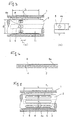
- Figure 1 is a view showing a contra-rotating bearing device for a contra-rotating propeller according to the first embodiment of the present invention, wherein (a) is a side sectional view and (b) is a sectional view taken along the line A - A of (a);
- Figures 2 (a) and (b) are sectional views showing an oil groove in the circumferential direction shown in Figure 1;
- Figure 3 is a view showing an example of dimensions according to the first embodiment in Figure 1, wherein (a) is a side sectional view and (b) is an enlarged view showing the oil groove;
- Figure 4 is a side sectional view showing another example of the axial section of the oil groove in Figure 1;
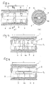
- Figure 5 is a side sectional view showing the second embodiment of the present invention;
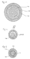
- Figure 6 is a view showing the third embodiment of the present invention, wherein (a) is a sectional view and (b) is a sectional view taken along the line B - B of (a);
- Figure 7 is a side sectional view showing the fourth embodiment of the present invention;
- Figure 8 is a side sectional view showing the fifth embodiment of the present invention;
- Figure 9 is a partial broken side view showing a contra-rotating propeller according to the prior art;
- Figure 10 is a sectional view taken along the line E - E in Figure 9;
- Figure 11 is a sectional view showing a contra-rotating bearing device for a contra-rotating propeller according to the prior art;
- Figure 12 is a sectional view showing another contra-rotating bearing device for a contra-rotating propeller according to the prior art;
- Figure 13 is a sectional view showing main parts of a stern tube bearing for a contra-rotating propeller based on a static pressure circular bearing according to the prior art; and
- Figure 14 is a view showing another contra-rotating bearing device for a contra-rotating propeller according to the prior art, wherein (a) is a side sectional view and (b) is a sectional view taken along the line F - F of (a).
-
- In the drawings for the following description, a radial clearance Cr and the like are exaggerated. In Fig. 1(a), the right side is the fore direction, and the left side is the after direction.
- As shown, an
outer shaft 1 for driving a front propeller of the contra-rotating propeller and aninner shaft 2 for driving a rear propeller are provided almost concentrically so as to rotate in mutually opposite directions. Theouter shaft 1 is supported by a journal bearing provided on a hull, which is not shown. Theinner shaft 2 is supported by the contra-rotating bearing device T1 formed in theouter shaft 1. - In the contra-rotating bearing device T1 according to the first embodiment, a hollow portion is provided on the core of the
inner shaft 2 to form anoil feed port 3, and a plurality of oil feed holes 4 which are connected with both of the outer peripheral face of the inner shaft and theoil feed port 3 are provided within a range L of a bearing surface. In the embodiment, the oil feed holes 4 are provided in a line on the rear end side within the range L of the bearing surface, that is, the after side having a greater load on the propeller side. In the first embodiment, eight oil feed holes 4 are radially provided.Axial oil grooves 5 are provided within the range L of the bearing surface on the outer peripheral face of the inner shaft including an inner shaft surfaceside opening portions 4a of the oil feed holes 4. According to the present embodiment, it is preferable that the number of the oil feed holes 4 should be three or more. - The
oil grooves 5 are formed from a plurality of oil feed holes 4 toward the fore side in the axial direction, and has a structure in which lubrication oil fed from the oil feed holes 4 generates a predetermined oil pressure that is necessary for the range L of the bearing surface along theoil groove 5. Theoil groove 5 can be easily processed because it is formed on the surface of theinner shaft 2. As shown by the sectional views of Figs. 2 (a) and (b), furthermore, theoil groove 5 may be a deep groove in (a) or a groove having a shallow oil reservoir in (b). In other words, it is sufficient that theoil groove 5 can generate a predetermined oil pressure within the range L of the bearing surface. As will be seen from Figures 2(a) and 2(b), the cross-sectional area of an oil groove is formed so as to be decreased from the inner shaft surface side opening portion the oil feed hole to ends thereof. - An example of dimensions obtained by an experiment in the contra-rotating bearing device T1 according to the first embodiment will be described below with reference to the side sectional view of Fig. 3 (a) and the enlarged view showing the oil groove of Fig. 3 (b). The following dimensions are variable depending on the loading conditions of the bearing, whose example will be described.
- As shown, the range of the bearing surface (bearing length) is expressed by L, the outer diameter of the inner shaft is expressed by D, a radius clearance is expressed by Cr, the axial length of the oil groove is expressed by v, a width is expressed by w, and oil is fed in eight directions on a section with L/D = in this example. Eight oil feed holes 4 are provided in a line in positions apart from the center of the range L of the bearing surface backward by a predetermined distance of L1. An
oil groove 5 having an axial length v and a width w is provided around an inner shaft surfaceside opening portion 4a of theoil feed hole 4. It is preferable that the predetermined distance L1 should be L/6 to L/4, the width w of theoil groove 5 should be πD/32 and the axial length v should be 1w to 2w. It is preferable that the depth of theoil groove 5 should be three to five times as much as the radius clearance Cr. According to general documents, a pressure drop can be ignored when the depth of theoil groove 5 is ten times as much as the radius clearance Cr or more. Consequently, it is supposed that a great change in the pressure is not caused in theoil groove 5 even through the depth of theoil groove 5 is three to five times as much as the radius clearance Cr or more. Therefore, if the position of theoil groove 5 is set, the pressure of theoil groove 5 is not changed greatly even though the position of theopening portion 4a of theoil feed hole 4 is changed axially. Thus, bearing performance is not affected greatly. - As shown by a sectional view of Fig. 4, the
oil groove 5 according to the first embodiment may be tapered in such a manner that it gradually becomes shallower from the position where theoil feed hole 4 is provided toward anend 5a, that is, an axial sectional area is decreased from the inner shaft surface side opening portion of theoil feed hole 4 to the end thereof. By such formation, a difference between an oil pressure in the position of theoil feed hole 4 and an oil pressure in the position of the end of theoil groove 5 can be made. Consequently, theoil feed hole 4 is provided in a position where a high oil pressure is necessary within the range L of the bearing surface to reduce the oil pressure in a position apart from theoil feed hole 4 so that the optimum pressure of the lubrication oil can be obtained over the range L of the bearing surface. In order to decrease the cross sectional area of theoil groove 5, a groove width, a groove depth or both of them can be decreased. - The contra-rotating bearing device T1 for a contra-rotating propeller having the above-mentioned structure according to the first embodiment functions as a contra-rotating bearing which supports the
inner shaft 2 in the following manner. - More specifically, the oil fed from the
oil feed port 3 of theinner shaft 2 is supplied to the inner shaft surface through theoil feed hole 4 and flows into the range L of the bearing surface along theoil groove 5. The contra-rotating bearing device T1 functions to generate a predetermined oil pressure within the range L of the bearing surface so that an oil film is formed and theinner shaft 2 is supported. Thus, the contra-rotating bearing device T1 can be formed by the oil feed holes 4 provided on theinner shaft 2 in a line. Consequently, a small number of oil feed holes 4 are provided on theinner shaft 2 so that the contra-rotating bearing device T1 can be formed without reducing an axial strength. - A contra-rotating bearing device T2 according to the second embodiment will be described below with reference to a side sectional view of Fig. 5. In the second embodiment, the
oil feed hole 4 according to the first embodiment is provided in almost the central portion within a range L of a bearing surface. Therefore, the same structures have the same reference numerals as in the first embodiment and their description will be omitted. - As shown, the
oil feed hole 4 according to the second embodiment is provided in almost the central portion within the range L of the bearing surface, and anoil groove 5 is provided from theoil feed hole 4 toward the fore and after sides within the range L of the bearing surface. - In case of the second embodiment, the width or depth of the
oil groove 5 provided from anopening portion 4a of theoil feed hole 4 toward the fore side and the width or depth of theoil groove 5 provided from theopening portion 4a toward the after side are set to optimum values so that an oil pressure within the range L of the bearing surface can be controlled to obtain an optimum function as the contra-rotating bearing device T2. Also in the second embodiment, the same functions and effects as in the first embodiment can be obtained. - A contra-rotating bearing device T3 according to the third embodiment will be described below with reference to a side sectional view in figs. 6 (a) and (b) and a sectional view taken along the line B - B in Figs. 6 (a) and (b). The same structures have the same reference numerals as in the first embodiment and their description will be omitted.
- In the third embodiment, oil feed holes 4 are axially provided in a plurality of lines, that is, three lines within a range L of a bearing surface, each line having two oil feed holes 4 as shown. The oil feed holes 4 are provided in positions where the phases of the first and the second lines are shifted (hereinafter referred to as "offset") by 90 degrees in the circumferential direction. The oil feed holes 4 are provided in positions where the second and third lines are offset by 90 degrees.
Oil grooves 6 are provided in the circumferential direction within the range L of the bearing surface including inner shaft surfaceside opening portions 4a of the oil feed holes 4. Also in the third embodiment, the surface of aninner shaft 2 is processed. Consequently, processing can be easily performed in the same manner as in the first embodiment. - The contra-rotating bearing device T3 for a contra-rotating propeller having the above-mentioned structure according to the third embodiment functions to support the
inner shaft 2 in the following manner. - More specifically, oil fed from an
oil feed port 3 of theinner shaft 2 is supplied from the oil feed holes 4 which are axially provided in a plurality of lines into the range L of the bearing surface, and a predetermined oil pressure is generated on the surface of theinner shaft 2 to form an oil film. Thus, the contra-rotating bearing function can be displayed. Since the propeller is provided on the after side, a load is usually great on the after side. Therefore, it is sufficient that the oil pressure is generated within the range L of the bearing surface corresponding to the load therein by setting the diameters of the oil feed holes 4, the width of theoil groove 6, the depth of theoil groove 6 and the like on the after and fore sides to optimum values. Other functions and effects are the same as in the first embodiment. - A contra-rotating bearing device T4 according to the fourth embodiment will be described below with reference to a side sectional view of Fig. 7. In the fourth embodiment, the number of oil feed holes 4 which are axially provided in the third embodiment is increased and the oil feed holes 4 are offset by a predetermined amount. The same structures have the same reference numerals as in the third embodiment and their description will be omitted.
- In the fourth embodiment, the oil feed holes 4 are axially provided in a plurality of lines, that is, five lines within a range L of a bearing surface, each line having two oil feed holes 4 as shown. The oil feed holes 4 are provided in such a manner that the first and the second lines are shifted in the circumferential direction, that is offset, by 45 degrees. The second and the third lines are also offset by 45 degrees, and the following lines are sequentially offset by 45 degrees.
Oil grooves 6 are provided in the circumferential direction within the range L of the bearing surface including an inner shaft surfaceside opening portions 4a of the oil feed holes 4. Also in the fourth embodiment, the surface of aninner shaft 2 is processed. Consequently, processing can be easily performed. - The contra-rotating bearing device T4 for a contra-rotating propeller having the above-mentioned structure according to the fourth embodiment functions in the same manner as the contra-rotating bearing device T3 for a contra-rotating propeller in the third embodiment described above.
- More specifically, oil fed from an
oil feed port 3 of theinner shaft 2 is supplied into the range L of the bearing surface through the oil feed holes 4 which are axially provided in a plurality of lines, and a predetermined oil pressure is operated on the surface of theinner shaft 2 to form an oil film. Thus, the contra-rotating bearing function can be displayed. According to the fourth embodiment, the oil feed holes 4 are axially provided in more lines than in the third embodiment. Consequently, the oil pressure can be controlled corresponding to a load within the range L of the bearing surface. Other functions and effects are the same as in the third embodiment described above. - A contra-rotating bearing device T5 according to the fifth embodiment will be described below with reference to a side sectional view of Fig. 8. In the fifth embodiment, a circumferential oil groove in the third embodiment is changed into an axial oil groove. As shown, oil feed holes 4 are axially provided in a plurality of lines, that is, three lines within a range L of a bearing surface, each line having two oil feed holes 4 in the same manner as in the third embodiment. The oil feed holes 4 are provided in positions where the first and the second lines are circumferentially offset by 90 degrees. The second and the third lines are also offset by 90 degrees.
Oil grooves 5 are axially provided within the range L of the bearing surface including inner shaft surfaceside opening portions 4a of the oil feed holes 4. - The contra-rotating bearing device T5 for a contra-rotating propeller having the above-mentioned structure according to the fifth embodiment functions in the same manner as the contra-rotating bearing device T3 in the third embodiment described above.
- More specifically, oil fed from the
oil feed port 3 of theinner shaft 2 is supplied into the range L of the bearing surface through the oil feed holes 4 which are axially provided in a plurality of lines, and a predetermined oil pressure is generated on the surface of theinner shaft 2 to form an oil film. Thus, the contra-rotating bearing function can be obtained. Also in the fifth embodiment, the oil pressure corresponding to a load within the range L of the bearing surface can be generated by setting the diameters of the oil feed holes 4, the width of theoil groove 5, the depth of theoil groove 5 and the like on the after and fore sides to optimum values in the same manner as in the third embodiment, or by making the tapered shape as shown in Fig. 4. - With the embodiments hereinbefore described a sufficient oil film is formed on the bearing surface which supports the inner shaft of the contra-rotating propeller so that an excellent bearing function can be obtained. The embodiments display the bearing function of a contra-rotating bearing when an inner shaft and an outer shaft rotate in mutually opposite directions at almost equal speeds, and are particularly suitable for a large-sized contra-rotating propeller of a ship or the like.
- An excellent bearing function can be obtained as a contra-rotating bearing which supports an inner shaft of a contra-rotating propeller in which the inner shaft and an outer shaft rotate in mutually opposite directions, which is useful for the general contra-rotating bearing device for supporting the inner shaft of the contra-rotating propeller, and more particularly suitable for a contra-rotating bearing device for a contra-rotating propeller of a ship which is provided with a large-sized contra-rotating propeller requiring a great load carrying capacity.
Claims (5)
- A contra-rotating bearing device for a contra-rotating propeller comprising an inner shaft for driving a rear propeller and an outer shaft for driving a front propeller, both shafts rotating in mutually opposite directions, wherein a hollow portion is provided on the core of the inner shaft to form an oil feed port, a plurality of oil feed holes which are connected with both of the outer peripheral face of the inner shaft within the range of the bearing surface of the inner shaft and the oil feed port are radially provided, characterised in that oil grooves, each of which includes an inner shaft surface side opening portion of the oil feed hole, are provided on the outer peripheral face of the inner shaft.
- A contra-rotating bearing device for a contra-rotating propeller as defined in Claim 1, wherein a plurality of said oil feed holes are radially provided in a line and said oil grooves are axially provided.
- A contra-rotating bearing device for a contra-rotating propeller as defined in Claim 1, wherein a plurality of said oil feed holes are radially provided, the oil feed holes being axially provided in a plurality of lines, and said oil grooves are circumferential or axial.
- A contra-rotating bearing device for a contra-rotating propeller as defined in Claim 3, wherein the oil feed holes which are axially provided in a plurality of lines are offset circumferentially.
- A contra-rotating bearing device for a contra-rotating propeller as defined in any of Claims 1 to 4, wherein the cross sectional area of a said oil groove is formed so as to be decreased from the inner shaft surface side opening portion of the oil feed hole to ends thereof.
Priority Applications (1)
| Application Number | Priority Date | Filing Date | Title |
|---|---|---|---|
| EP00112763A EP1035013B1 (en) | 1994-09-08 | 1995-09-04 | Contra-rotating bearing device for contra-rotating propeller |
Applications Claiming Priority (7)
| Application Number | Priority Date | Filing Date | Title |
|---|---|---|---|
| JP21470194A JP3432303B2 (en) | 1994-09-08 | 1994-09-08 | Reversing bearing for contra-rotating propeller |
| JP214701/94 | 1994-09-08 | ||
| JP21470194 | 1994-09-08 | ||
| JP222740/95 | 1995-08-09 | ||
| JP22274095A JP3364735B2 (en) | 1995-08-09 | 1995-08-09 | Bearing device for contra-rotating propeller |
| JP22274095 | 1995-08-09 | ||
| PCT/JP1995/001761 WO1996007832A1 (en) | 1994-09-08 | 1995-09-04 | Reversing bearing device for double reversing propeller |
Related Child Applications (1)
| Application Number | Title | Priority Date | Filing Date |
|---|---|---|---|
| EP00112763A Division EP1035013B1 (en) | 1994-09-08 | 1995-09-04 | Contra-rotating bearing device for contra-rotating propeller |
Publications (3)
| Publication Number | Publication Date |
|---|---|
| EP0803657A1 EP0803657A1 (en) | 1997-10-29 |
| EP0803657A4 EP0803657A4 (en) | 1999-06-30 |
| EP0803657B1 true EP0803657B1 (en) | 2003-01-15 |
Family
ID=26520463
Family Applications (2)
| Application Number | Title | Priority Date | Filing Date |
|---|---|---|---|
| EP00112763A Expired - Lifetime EP1035013B1 (en) | 1994-09-08 | 1995-09-04 | Contra-rotating bearing device for contra-rotating propeller |
| EP95930041A Expired - Lifetime EP0803657B1 (en) | 1994-09-08 | 1995-09-04 | Reversing bearing device for double reversing propeller |
Family Applications Before (1)
| Application Number | Title | Priority Date | Filing Date |
|---|---|---|---|
| EP00112763A Expired - Lifetime EP1035013B1 (en) | 1994-09-08 | 1995-09-04 | Contra-rotating bearing device for contra-rotating propeller |
Country Status (7)
| Country | Link |
|---|---|
| US (1) | US6056509A (en) |
| EP (2) | EP1035013B1 (en) |
| KR (1) | KR100243070B1 (en) |
| DE (2) | DE69529422T2 (en) |
| DK (2) | DK0803657T3 (en) |
| ES (2) | ES2202372T3 (en) |
| WO (1) | WO1996007832A1 (en) |
Families Citing this family (22)
| Publication number | Priority date | Publication date | Assignee | Title |
|---|---|---|---|---|
| JP2000002233A (en) * | 1998-06-12 | 2000-01-07 | Sumitomo Electric Ind Ltd | Dynamic pressure gas bearing and its manufacture |
| CN100414164C (en) * | 2004-01-20 | 2008-08-27 | 郑红专 | Oil balance device and shaft using oil balance device |
| US20060078239A1 (en) * | 2004-09-01 | 2006-04-13 | Florin Dimofte | Wave bearings in high performance applications |
| FR2895480A3 (en) * | 2005-12-22 | 2007-06-29 | Renault Sas | Internal combustion engine`s balancing shaft for motor vehicle, has transversal grooves provided in surface zone that is situated diametrically opposed to load zone, where surface zone is different from load zone |
| DE102008003698A1 (en) * | 2008-01-09 | 2009-07-23 | Neuman & Esser Maschinenfabrik Gmbh & Co. Kg | Crosshead bearing |
| KR100990306B1 (en) * | 2008-10-02 | 2010-10-26 | 현대중공업 주식회사 | Device for Lubrication Oil Path in Journal Bearing of Contra-rotating Propeller Shaft |
| US8740563B2 (en) * | 2010-11-22 | 2014-06-03 | General Electric Company | Sealing assembly for use in turbomachines and methods of assembling same |
| JP2012193709A (en) * | 2011-03-17 | 2012-10-11 | Toyota Industries Corp | Bearing structure of turbocharger |
| US8690721B2 (en) | 2011-08-02 | 2014-04-08 | United Technologies Corporation | Journal pin oil supply for gear system |
| JP5602122B2 (en) * | 2011-12-13 | 2014-10-08 | 日立Geニュークリア・エナジー株式会社 | Slide bearing and pump device using the same |
| KR101487663B1 (en) | 2012-12-04 | 2015-02-03 | 삼성중공업 주식회사 | Propulsion apparatus for ship, and ship having the same |
| US9284976B2 (en) | 2013-03-09 | 2016-03-15 | Waukesha Bearings Corporation | Countershaft |
| US9279446B2 (en) | 2013-03-09 | 2016-03-08 | Waukesha Bearings Corporation | Bearing with axial variation |
| FR3016406B1 (en) * | 2014-01-10 | 2016-02-12 | Snecma | TURBOMACHINE ASSEMBLY COMPRISING TWO BODIES AND MEANS FOR GUIDING A FLOWABLE FLUID FROM ONE BODY TO THE OTHER |
| DE102014200594A1 (en) * | 2014-01-15 | 2015-07-16 | Voith Patent Gmbh | Hydrodynamic plain bearing |
| CN105473879A (en) * | 2014-03-10 | 2016-04-06 | 沃喀莎轴承公司 | Countershaft |
| US9562602B2 (en) * | 2014-07-07 | 2017-02-07 | Solar Turbines Incorporated | Tri-lobe bearing for a gearbox |
| CN105508443A (en) * | 2014-10-14 | 2016-04-20 | 摩尔动力(北京)技术股份有限公司 | Large-gap bearing system |
| FR3028903B1 (en) * | 2014-11-20 | 2017-05-05 | Snecma | SELF-CENTER SMOOTH BEARING |
| US11460042B2 (en) * | 2019-02-27 | 2022-10-04 | Mitsubishi Heavy Industries Engine & Turbocharger, Ltd. | Floating bush bearing device and supercharger |
| US11821364B2 (en) * | 2021-08-20 | 2023-11-21 | Pratt & Whitney Canada Corp. | Shaped cavity at interface between journal bearing and rotor |
| US20230313706A1 (en) * | 2022-03-29 | 2023-10-05 | Pratt & Whitney Canada Corp. | Journal bearing with oil pocket |
Family Cites Families (40)
| Publication number | Priority date | Publication date | Assignee | Title |
|---|---|---|---|---|
| GB380660A (en) * | 1930-12-05 | 1932-09-22 | Gen Electric | Improvements in and relating to shaft bearings |
| US2470560A (en) * | 1939-06-13 | 1949-05-17 | Walter S Hoover | Oppositely rotating propellers |
| US2348274A (en) * | 1943-07-28 | 1944-05-09 | Evender S Aker | Shaft journaling means |
| US2348275A (en) * | 1943-07-28 | 1944-05-09 | Evender S Aker | Shaft journal |
| US2457999A (en) * | 1946-03-28 | 1949-01-04 | Continental Aviat & Eng Corp | Lubrication means for dual propeller shaft assemblies |
| DE903054C (en) * | 1948-10-01 | 1954-02-01 | Dr Wilhelm Froessel | Multi-slide bearing |
| US3167361A (en) * | 1963-05-28 | 1965-01-26 | Ralph B Snapp | Rotating bearing |
| US3317254A (en) * | 1963-12-19 | 1967-05-02 | Satterthwaite James Glenn | Demountable marine bearing |
| FR1559502A (en) * | 1967-04-10 | 1969-03-07 | ||
| US3466952A (en) * | 1967-12-06 | 1969-09-16 | Babcock & Wilcox Co | Hydrostatic bearing supported boring bar |
| US3515449A (en) * | 1968-09-10 | 1970-06-02 | Us Navy | Soft rubber squeeze film bearing |
| US3637273A (en) * | 1970-01-26 | 1972-01-25 | Goodrich Co B F | Elastomeric bearing |
| US3889626A (en) * | 1972-05-16 | 1975-06-17 | Mitsui Shipbuilding Eng | Stern tube bearing |
| JPS554964B2 (en) * | 1974-01-18 | 1980-02-02 | ||
| US4307918A (en) * | 1978-05-17 | 1981-12-29 | National Research Development Corporation | Bearings |
| CH636679A5 (en) * | 1979-03-01 | 1983-06-15 | Sulzer Ag | HYDROSTATIC BEARING FOR A RADIAL PISTON MACHINE. |
| US4366993A (en) * | 1980-01-07 | 1983-01-04 | Nippon Telegraph & Telephone Corp. | Gas bearings |
| JPS58149415A (en) * | 1982-02-26 | 1983-09-05 | Hitachi Ltd | Anti-oscillation bearing |
| JPS58217819A (en) * | 1982-06-11 | 1983-12-17 | Hitachi Ltd | Eccentric shaft |
| DE3231133A1 (en) * | 1982-08-21 | 1984-02-23 | Zahnräderfabrik Renk AG, 8900 Augsburg | HYDRODYNAMIC BEARING ARRANGEMENT |
| DE3332357C1 (en) * | 1983-09-08 | 1985-04-04 | Klein, Schanzlin & Becker Ag, 6710 Frankenthal | Hydrostatic-hydrodynamic hybrid multi-surface radial bearing |
| EP0158242B1 (en) * | 1984-04-09 | 1988-08-10 | Arcomac S.A. | Sliding contact bearing for radial load |
| JPS61236921A (en) * | 1985-04-12 | 1986-10-22 | Mitsubishi Heavy Ind Ltd | Static pressure bearing |
| KR900004060B1 (en) * | 1985-11-08 | 1990-06-11 | 미쯔비시주우고오교오 가부시기가이샤 | Stern tube bearing system of contra-rotating propeller |
| JPS62110595A (en) * | 1985-11-08 | 1987-05-21 | Mitsubishi Heavy Ind Ltd | Stern tube bearing for double reversal propeller |
| ES2017079B3 (en) * | 1986-05-23 | 1991-01-01 | Mitsubishi Heavy Ind Ltd | INVERTED TURN DOUBLE HELICE APPARATUS. |
| NL8602565A (en) * | 1986-10-13 | 1988-05-02 | Philips Nv | BEARING SYSTEM WITH AN ACTIVE RESERVOIR BETWEEN TWO AXIAL DISTANCE HYDRODYNAMIC BEARINGS. |
| JP2516967B2 (en) * | 1987-04-30 | 1996-07-24 | 松下電器産業株式会社 | Bearing device |
| JPS6455418A (en) * | 1987-08-25 | 1989-03-02 | Matsushita Electric Ind Co Ltd | Bearing device |
| US5017023A (en) * | 1990-05-24 | 1991-05-21 | Rockwell International Corporation | Asymmetrically stepped hydrostatic bearing |
| US5169242A (en) * | 1990-11-27 | 1992-12-08 | General Motors Corporation | Turbocharger assembly and stabilizing journal bearing therefor |
| US5143455A (en) * | 1991-02-25 | 1992-09-01 | Squyres Richard T | Bearing sleeve with notched end |
| JP3089727B2 (en) | 1991-08-14 | 2000-09-18 | ソニー株式会社 | Portable electronic devices |
| DE4232753C2 (en) * | 1992-09-30 | 2001-03-08 | Blohm & Voss Ind Gmbh | Lubrication system for sealing propeller drives for ships with two counter-rotating propellers arranged concentrically to each other |
| DE4235737C2 (en) * | 1992-10-23 | 2000-11-30 | Blohm & Voss Ind Gmbh | Stern tube bearing system for counter-rotating propellers |
| JP2902262B2 (en) * | 1993-03-29 | 1999-06-07 | 光洋精工株式会社 | Hydrodynamic bearing |
| GB9408485D0 (en) * | 1994-04-27 | 1994-06-22 | Martin James K | Fluid film bearings |
| MC219A7 (en) * | 1994-08-10 | 1996-03-29 | Antonio Pedone | Watertight floating seal for boat propeller shafts with safety device |
| US5456535A (en) * | 1994-08-15 | 1995-10-10 | Ingersoll-Rand Company | Journal bearing |
| JP3069039B2 (en) * | 1996-02-02 | 2000-07-24 | 日本電産コパル電子株式会社 | Dynamic gas bearing |
-
1995
- 1995-09-04 ES ES95930041T patent/ES2202372T3/en not_active Expired - Lifetime
- 1995-09-04 EP EP00112763A patent/EP1035013B1/en not_active Expired - Lifetime
- 1995-09-04 DE DE69529422T patent/DE69529422T2/en not_active Expired - Lifetime
- 1995-09-04 WO PCT/JP1995/001761 patent/WO1996007832A1/en active IP Right Grant
- 1995-09-04 DE DE69529432T patent/DE69529432T2/en not_active Expired - Lifetime
- 1995-09-04 ES ES00112763T patent/ES2190919T3/en not_active Expired - Lifetime
- 1995-09-04 EP EP95930041A patent/EP0803657B1/en not_active Expired - Lifetime
- 1995-09-04 KR KR1019970700181A patent/KR100243070B1/en not_active IP Right Cessation
- 1995-09-04 DK DK95930041T patent/DK0803657T3/en active
- 1995-09-04 DK DK00112763T patent/DK1035013T3/en active
-
1997
- 1997-03-06 US US08/809,339 patent/US6056509A/en not_active Expired - Lifetime
Also Published As
| Publication number | Publication date |
|---|---|
| EP0803657A4 (en) | 1999-06-30 |
| ES2202372T3 (en) | 2004-04-01 |
| DE69529432T2 (en) | 2003-10-30 |
| DK0803657T3 (en) | 2003-05-12 |
| EP1035013A2 (en) | 2000-09-13 |
| EP1035013B1 (en) | 2003-01-15 |
| KR100243070B1 (en) | 2000-03-02 |
| DE69529422D1 (en) | 2003-02-20 |
| DK1035013T3 (en) | 2003-05-12 |
| ES2190919T3 (en) | 2003-09-01 |
| WO1996007832A1 (en) | 1996-03-14 |
| DE69529422T2 (en) | 2003-10-30 |
| DE69529432D1 (en) | 2003-02-20 |
| EP1035013A3 (en) | 2000-12-06 |
| KR970704973A (en) | 1997-09-06 |
| EP0803657A1 (en) | 1997-10-29 |
| US6056509A (en) | 2000-05-02 |
Similar Documents
| Publication | Publication Date | Title |
|---|---|---|
| EP0803657B1 (en) | Reversing bearing device for double reversing propeller | |
| JP2501167B2 (en) | Lubricant oil supply device for marine counter-rotating propeller | |
| US4558960A (en) | Radial friction bearing assembly | |
| US5366398A (en) | Marine dual propeller lower bore drive assembly | |
| KR20040018903A (en) | Bearing equipment | |
| JP2005256917A (en) | Sliding bearing | |
| JPH09144750A (en) | Pad type journal bearing | |
| JP3432303B2 (en) | Reversing bearing for contra-rotating propeller | |
| US11391354B2 (en) | Gear for differential and differential | |
| EP0221536B1 (en) | Stern tube bearing system of contra-rotating propeller | |
| JP2002515105A (en) | Self pump operated roller bearing | |
| US5462463A (en) | Marine dual propeller lower bore drive assembly | |
| JP2004098719A (en) | Stern tube bearing and its manufacturing method | |
| EP1475165B1 (en) | Triple bearing arrangement for cantilevered roll shafts | |
| JPH11336753A (en) | Self-aligning roller bearing | |
| JP3498269B2 (en) | Bearing device for contra-rotating propeller | |
| JPH06239294A (en) | Lubricating oil feed structure for marine contra-rotating propeller | |
| JPS62110595A (en) | Stern tube bearing for double reversal propeller | |
| JP3132950B2 (en) | Stern bearing for contra-rotating propeller | |
| JPH0716903Y2 (en) | Axial lubrication device | |
| JP2891521B2 (en) | Intermediate bearing structure for marine contra-rotating propeller shaft | |
| KR20130002301U (en) | Ball bearing having spacer ring | |
| JP4049036B2 (en) | Roller cutter | |
| JPH0522085B2 (en) | ||
| JPH0442235Y2 (en) |
Legal Events
| Date | Code | Title | Description |
|---|---|---|---|
| PUAI | Public reference made under article 153(3) epc to a published international application that has entered the european phase |
Free format text: ORIGINAL CODE: 0009012 |
|
| 17P | Request for examination filed |
Effective date: 19961217 |
|
| AK | Designated contracting states |
Kind code of ref document: A1 Designated state(s): DE DK ES FR GB IT NL SE |
|
| RIC1 | Information provided on ipc code assigned before grant |
Free format text: 6B 63H 23/32 A, 6F 16C 32/06 B, 6F 16C 33/10 B, 6B 63B 5/10 - |
|
| A4 | Supplementary search report drawn up and despatched |
Effective date: 19990518 |
|
| AK | Designated contracting states |
Kind code of ref document: A4 Designated state(s): DE DK ES FR GB IT NL SE |
|
| 17Q | First examination report despatched |
Effective date: 19991124 |
|
| GRAG | Despatch of communication of intention to grant |
Free format text: ORIGINAL CODE: EPIDOS AGRA |
|
| GRAG | Despatch of communication of intention to grant |
Free format text: ORIGINAL CODE: EPIDOS AGRA |
|
| GRAH | Despatch of communication of intention to grant a patent |
Free format text: ORIGINAL CODE: EPIDOS IGRA |
|
| GRAH | Despatch of communication of intention to grant a patent |
Free format text: ORIGINAL CODE: EPIDOS IGRA |
|
| GRAA | (expected) grant |
Free format text: ORIGINAL CODE: 0009210 |
|
| AK | Designated contracting states |
Kind code of ref document: B1 Designated state(s): DE DK ES FR GB IT NL SE |
|
| REG | Reference to a national code |
Ref country code: GB Ref legal event code: FG4D |
|
| REF | Corresponds to: |
Ref document number: 69529422 Country of ref document: DE Date of ref document: 20030220 Kind code of ref document: P |
|
| REG | Reference to a national code |
Ref country code: SE Ref legal event code: TRGR |
|
| REG | Reference to a national code |
Ref country code: DK Ref legal event code: T3 |
|
| ET | Fr: translation filed | ||
| RAP2 | Party data changed (patent owner data changed or rights of a patent transferred) |
Owner name: MITSUI ENGINEERING & SHIPBUILDING CO., LTD Owner name: UNIVERSAL SHIPBUILDING CORPORATION Owner name: SUMITOMO HEAVY INDUSTRIES, LTD. Owner name: KAWASAKI JUKOGYO KABUSHIKI KAISHA |
|
| PLBE | No opposition filed within time limit |
Free format text: ORIGINAL CODE: 0009261 |
|
| STAA | Information on the status of an ep patent application or granted ep patent |
Free format text: STATUS: NO OPPOSITION FILED WITHIN TIME LIMIT |
|
| NLS | Nl: assignments of ep-patents |
Owner name: UNIVERSAL SHIPBUILDING CORPORATION Owner name: SUMITOMO HEAVY INDUSTRIES, LTD. Owner name: MITSUI ENGINEERING & SHIPBUILDING CO., LTD Owner name: KAWASAKI JUKOGYO KABUSHIKI KAISHA |
|
| NLT2 | Nl: modifications (of names), taken from the european patent patent bulletin |
Owner name: KAWASAKI JUKOGYO KABUSHIKI KAISHA EN SUMITOMO HEAV |
|
| RAP2 | Party data changed (patent owner data changed or rights of a patent transferred) |
Owner name: KABUSHIKI KAISHA KAWASAKI ZOSEN Owner name: MITSUI ENGINEERING & SHIPBUILDING CO., LTD Owner name: UNIVERSAL SHIPBUILDING CORPORATION Owner name: SUMITOMO HEAVY INDUSTRIES, LTD. Owner name: KAWASAKI JUKOGYO KABUSHIKI KAISHA |
|
| 26N | No opposition filed |
Effective date: 20031016 |
|
| NLS | Nl: assignments of ep-patents |
Owner name: UNIVERSAL SHIPBUILDING CORPORATION Owner name: SUMITOMO HEAVY INDUSTRIES CO., LTD. Owner name: MITSUI ENGINEERING & SHIPBUILDING CO., LTD Owner name: KAWASAKI JUKOGYO KABUSHIKI KAISHA Owner name: KABUSHIKI KAISHA KAWASAKI ZOSEN |
|
| NLT2 | Nl: modifications (of names), taken from the european patent patent bulletin |
Owner name: KAWASAKI JUKOGYO KABUSHIKI KAISHA EN SUMITOMO HEAV |
|
| REG | Reference to a national code |
Ref country code: GB Ref legal event code: 732E |
|
| REG | Reference to a national code |
Ref country code: ES Ref legal event code: FG2A Ref document number: 2202372 Country of ref document: ES Kind code of ref document: T3 |
|
| REG | Reference to a national code |
Ref country code: GB Ref legal event code: 732E Free format text: REGISTERED BETWEEN 20110331 AND 20110406 |
|
| REG | Reference to a national code |
Ref country code: NL Ref legal event code: SD Effective date: 20110901 |
|
| REG | Reference to a national code |
Ref country code: DE Ref legal event code: R082 Ref document number: 69529422 Country of ref document: DE Representative=s name: TER MEER STEINMEISTER & PARTNER GBR PATENTANWA, DE |
|
| PGFP | Annual fee paid to national office [announced via postgrant information from national office to epo] |
Ref country code: DK Payment date: 20110912 Year of fee payment: 17 |
|
| REG | Reference to a national code |
Ref country code: DE Ref legal event code: R082 Ref document number: 69529422 Country of ref document: DE Representative=s name: TER MEER STEINMEISTER & PARTNER PATENTANWAELTE, DE Effective date: 20110926 Ref country code: DE Ref legal event code: R081 Ref document number: 69529422 Country of ref document: DE Owner name: UNIVERSAL SHIPBUILDING CORP., JP Free format text: FORMER OWNERS: KABUSHIKI KAISHA KAWASAKI ZOSEN, KOBE, JP; KAWASAKI JUKOGYO K.K., KOBE, HYOGO, JP; SUMITOMO HEAVY INDUSTRIES, LTD., TOKYO, JP; UNIVERSAL SHIPBUILDING CORP., TOKIO/TOKYO, JP; MITSUI ENGINEERING & SHIPBUILDING CO. LTD., TOKIO/TOKYO, JP Effective date: 20110926 Ref country code: DE Ref legal event code: R081 Ref document number: 69529422 Country of ref document: DE Owner name: MITSUI ENGINEERING & SHIPBUILDING CO. LTD., JP Free format text: FORMER OWNERS: KABUSHIKI KAISHA KAWASAKI ZOSEN, KOBE, JP; KAWASAKI JUKOGYO K.K., KOBE, HYOGO, JP; SUMITOMO HEAVY INDUSTRIES, LTD., TOKYO, JP; UNIVERSAL SHIPBUILDING CORP., TOKIO/TOKYO, JP; MITSUI ENGINEERING & SHIPBUILDING CO. LTD., TOKIO/TOKYO, JP Effective date: 20110926 Ref country code: DE Ref legal event code: R081 Ref document number: 69529422 Country of ref document: DE Owner name: SUMITOMO HEAVY INDUSTRIES, LTD., JP Free format text: FORMER OWNERS: KABUSHIKI KAISHA KAWASAKI ZOSEN, KOBE, JP; KAWASAKI JUKOGYO K.K., KOBE, HYOGO, JP; SUMITOMO HEAVY INDUSTRIES, LTD., TOKYO, JP; UNIVERSAL SHIPBUILDING CORP., TOKIO/TOKYO, JP; MITSUI ENGINEERING & SHIPBUILDING CO. LTD., TOKIO/TOKYO, JP Effective date: 20110926 Ref country code: DE Ref legal event code: R081 Ref document number: 69529422 Country of ref document: DE Owner name: KAWASAKI JUKOGYO K.K., KOBE, JP Free format text: FORMER OWNERS: KABUSHIKI KAISHA KAWASAKI ZOSEN, KOBE, JP; KAWASAKI JUKOGYO K.K., KOBE, HYOGO, JP; SUMITOMO HEAVY INDUSTRIES, LTD., TOKYO, JP; UNIVERSAL SHIPBUILDING CORP., TOKIO/TOKYO, JP; MITSUI ENGINEERING & SHIPBUILDING CO. LTD., TOKIO/TOKYO, JP Effective date: 20110926 Ref country code: DE Ref legal event code: R081 Ref document number: 69529422 Country of ref document: DE Owner name: MITSUI ENGINEERING & SHIPBUILDING CO. LTD., JP Free format text: FORMER OWNER: KABUSHIKI KAISHA KAWASAKI ZOSEN, KAWASAKI JUKOGYO K.K., SUMITOMO HEAVY INDUSTRIES, LTD., UNIVERSAL SHIPBUILDING CORP., MITSUI EN, , JP Effective date: 20110926 Ref country code: DE Ref legal event code: R081 Ref document number: 69529422 Country of ref document: DE Owner name: SUMITOMO HEAVY INDUSTRIES, LTD., JP Free format text: FORMER OWNER: KABUSHIKI KAISHA KAWASAKI ZOSEN, KAWASAKI JUKOGYO K.K., SUMITOMO HEAVY INDUSTRIES, LTD., UNIVERSAL SHIPBUILDING CORP., MITSUI EN, , JP Effective date: 20110926 Ref country code: DE Ref legal event code: R081 Ref document number: 69529422 Country of ref document: DE Owner name: UNIVERSAL SHIPBUILDING CORP., JP Free format text: FORMER OWNER: KABUSHIKI KAISHA KAWASAKI ZOSEN, KAWASAKI JUKOGYO K.K., SUMITOMO HEAVY INDUSTRIES, LTD., UNIVERSAL SHIPBUILDING CORP., MITSUI EN, , JP Effective date: 20110926 Ref country code: DE Ref legal event code: R081 Ref document number: 69529422 Country of ref document: DE Owner name: KAWASAKI JUKOGYO K.K., JP Free format text: FORMER OWNER: KABUSHIKI KAISHA KAWASAKI ZOSEN, KAWASAKI JUKOGYO K.K., SUMITOMO HEAVY INDUSTRIES, LTD., UNIVERSAL SHIPBUILDING CORP., MITSUI EN, , JP Effective date: 20110926 |
|
| REG | Reference to a national code |
Ref country code: FR Ref legal event code: TQ Owner name: MITSUI ENGINEERING AND SHIPBUILDING CO, LTD., JP Effective date: 20111108 Ref country code: FR Ref legal event code: TQ Owner name: SUMITOMO HEAVY INDUSTRIES, LTD., JP Effective date: 20111108 Ref country code: FR Ref legal event code: TQ Owner name: UNIVERSAL SHIPBUILDING CORPORATIO Effective date: 20111108 Ref country code: FR Ref legal event code: TQ Owner name: KAWASAKI JUKOGYO KABUSHIKI KAISHA Effective date: 20111108 |
|
| REG | Reference to a national code |
Ref country code: ES Ref legal event code: PC2A Owner name: KAWASAKI JOKOGYO KABUSHIKI KAISHA Effective date: 20120217 |
|
| PGFP | Annual fee paid to national office [announced via postgrant information from national office to epo] |
Ref country code: SE Payment date: 20120911 Year of fee payment: 18 Ref country code: GB Payment date: 20120829 Year of fee payment: 18 |
|
| PGFP | Annual fee paid to national office [announced via postgrant information from national office to epo] |
Ref country code: DE Payment date: 20120829 Year of fee payment: 18 Ref country code: IT Payment date: 20120915 Year of fee payment: 18 Ref country code: FR Payment date: 20120926 Year of fee payment: 18 |
|
| PGFP | Annual fee paid to national office [announced via postgrant information from national office to epo] |
Ref country code: NL Payment date: 20120908 Year of fee payment: 18 |
|
| PGFP | Annual fee paid to national office [announced via postgrant information from national office to epo] |
Ref country code: ES Payment date: 20121004 Year of fee payment: 18 |
|
| REG | Reference to a national code |
Ref country code: NL Ref legal event code: V1 Effective date: 20140401 |
|
| REG | Reference to a national code |
Ref country code: SE Ref legal event code: EUG |
|
| PG25 | Lapsed in a contracting state [announced via postgrant information from national office to epo] |
Ref country code: SE Free format text: LAPSE BECAUSE OF NON-PAYMENT OF DUE FEES Effective date: 20130905 |
|
| REG | Reference to a national code |
Ref country code: DK Ref legal event code: EBP Effective date: 20130930 |
|
| GBPC | Gb: european patent ceased through non-payment of renewal fee |
Effective date: 20130904 |
|
| REG | Reference to a national code |
Ref country code: FR Ref legal event code: ST Effective date: 20140530 |
|
| REG | Reference to a national code |
Ref country code: DE Ref legal event code: R119 Ref document number: 69529422 Country of ref document: DE Effective date: 20140401 |
|
| PG25 | Lapsed in a contracting state [announced via postgrant information from national office to epo] |
Ref country code: GB Free format text: LAPSE BECAUSE OF NON-PAYMENT OF DUE FEES Effective date: 20130904 |
|
| PG25 | Lapsed in a contracting state [announced via postgrant information from national office to epo] |
Ref country code: FR Free format text: LAPSE BECAUSE OF NON-PAYMENT OF DUE FEES Effective date: 20130930 Ref country code: IT Free format text: LAPSE BECAUSE OF NON-PAYMENT OF DUE FEES Effective date: 20130904 Ref country code: DE Free format text: LAPSE BECAUSE OF NON-PAYMENT OF DUE FEES Effective date: 20140401 Ref country code: NL Free format text: LAPSE BECAUSE OF NON-PAYMENT OF DUE FEES Effective date: 20140401 |
|
| REG | Reference to a national code |
Ref country code: ES Ref legal event code: FD2A Effective date: 20141007 |
|
| PG25 | Lapsed in a contracting state [announced via postgrant information from national office to epo] |
Ref country code: DK Free format text: LAPSE BECAUSE OF NON-PAYMENT OF DUE FEES Effective date: 20130930 |
|
| PG25 | Lapsed in a contracting state [announced via postgrant information from national office to epo] |
Ref country code: ES Free format text: LAPSE BECAUSE OF NON-PAYMENT OF DUE FEES Effective date: 20130905 |