EP0803606A2 - Rouleau à réglage de la flexion - Google Patents
Rouleau à réglage de la flexion Download PDFInfo
- Publication number
- EP0803606A2 EP0803606A2 EP97102072A EP97102072A EP0803606A2 EP 0803606 A2 EP0803606 A2 EP 0803606A2 EP 97102072 A EP97102072 A EP 97102072A EP 97102072 A EP97102072 A EP 97102072A EP 0803606 A2 EP0803606 A2 EP 0803606A2
- Authority
- EP
- European Patent Office
- Prior art keywords
- roller
- fluid
- elements
- deflection compensation
- fluid wiping
- Prior art date
- Legal status (The legal status is an assumption and is not a legal conclusion. Google has not performed a legal analysis and makes no representation as to the accuracy of the status listed.)
- Granted
Links
Images
Classifications
-
- F—MECHANICAL ENGINEERING; LIGHTING; HEATING; WEAPONS; BLASTING
- F16—ENGINEERING ELEMENTS AND UNITS; GENERAL MEASURES FOR PRODUCING AND MAINTAINING EFFECTIVE FUNCTIONING OF MACHINES OR INSTALLATIONS; THERMAL INSULATION IN GENERAL
- F16C—SHAFTS; FLEXIBLE SHAFTS; ELEMENTS OR CRANKSHAFT MECHANISMS; ROTARY BODIES OTHER THAN GEARING ELEMENTS; BEARINGS
- F16C13/00—Rolls, drums, discs, or the like; Bearings or mountings therefor
- F16C13/02—Bearings
- F16C13/022—Bearings supporting a hollow roll mantle rotating with respect to a yoke or axle
- F16C13/024—Bearings supporting a hollow roll mantle rotating with respect to a yoke or axle adjustable for positioning, e.g. radial movable bearings for controlling the deflection along the length of the roll mantle
- F16C13/026—Bearings supporting a hollow roll mantle rotating with respect to a yoke or axle adjustable for positioning, e.g. radial movable bearings for controlling the deflection along the length of the roll mantle by fluid pressure
- F16C13/028—Bearings supporting a hollow roll mantle rotating with respect to a yoke or axle adjustable for positioning, e.g. radial movable bearings for controlling the deflection along the length of the roll mantle by fluid pressure with a plurality of supports along the length of the roll mantle, e.g. hydraulic jacks
-
- D—TEXTILES; PAPER
- D21—PAPER-MAKING; PRODUCTION OF CELLULOSE
- D21G—CALENDERS; ACCESSORIES FOR PAPER-MAKING MACHINES
- D21G1/00—Calenders; Smoothing apparatus
- D21G1/02—Rolls; Their bearings
- D21G1/0206—Controlled deflection rolls
- D21G1/0213—Controlled deflection rolls with deflection compensation means acting between the roller shell and its supporting member
- D21G1/022—Controlled deflection rolls with deflection compensation means acting between the roller shell and its supporting member the means using fluid pressure
Definitions
- the invention relates to a deflection compensating roller with a rotating roller shell, a yoke axially penetrating the roller shell and a plurality of hydrostatic and / or hydrodynamic support elements which are spaced apart from one another in the axial direction, by means of which the roller shell is supported on the yoke with the formation of an intermediate fluid cushion.
- the fluid in particular oil, for example supplied via the support elements, must at least partially be removed again from the interior of the roller.
- the deflection compensation roller is used as the bottom roller, fluid can be scraped off from the inner surface of the roller shell by the support sources located above and can be discharged with the aid of gravity. This is not possible when using the deflection compensation roller as a top roller with support sources below.
- a scoop ring is provided in a deflection compensating roller known from DE 25 50 366 A1, which is used as the top roller, and is arranged between the yoke and an end section of the roller shell.
- a problem with the previously known deflection compensation rollers is, in particular, that relatively thick oil rings can form in the roller, which in turn result in high splashing power losses, which occur in particular when flowing around the support sources.
- the aim of the invention is to provide a deflection compensating roller of the type mentioned in the introduction, in which the amount of fluid contained in the inside of the roller and, correspondingly, the associated splashing power losses are simply and reliably are also reduced to a minimum, especially when the roller is used as the top roller.
- the object is achieved according to the invention in that a plurality of fluid wiping elements distributed over its axial length are provided on the inner circumference of the roll shell and are arranged in a gap with respect to the support elements.
- the fluid wiping elements act specifically on the discrete fluid rings, which result from the fact that entrained fluid finally flows around the support sources.
- the amount of fluid contained in the inside of the roll can be reduced to a minimum, so that the fluid film layers formed on the inside of the roll are kept sufficiently thin.
- the splashing power losses that occur in particular when the support source flows around are correspondingly reduced.
- friction losses are kept low. These are significantly reduced compared to those of a continuous scraper blade.
- the axial length of the fluid wiping elements which are offset by half a division of the support source arrangement relative to the support sources, is at least equal to the distance between the support elements and preferably greater than this distance, which can in particular be approximately one third of the division of the support source arrangement. In this case, the friction losses can be reduced to about a third compared to a continuous scraper blade.
- At least some of the fluid wiping elements can be advantageously arranged, designed and / or acted upon such that they let through a respective fluid film with a thickness in the range of about 10 to 100 microns.
- the fluid wiping elements are at least partially arranged, designed and / or acted upon in such a way that they are effective only when the deflection compensating roller is used as an upper roller, in which they lie in the upper half of the roller, while they are used when the deflection compensating roller is used as an inferior roller, with which they lie in the lower half of the roller, remain ineffective.
- the support elements themselves can then again serve as wipers.
- the relevant fluid wiping elements are expediently arranged, designed and / or acted upon in such a way that they only move in one direction rotating roller jacket are effective while remaining ineffective with the roller jacket rotating in the opposite direction.
- the support elements can also be designed such that they flow around the fluid well in the direction of rotation of the roller shell that results for the top roller, while they strip off the fluid well when the roller shell rotates in the opposite direction.
- the deflection compensating roller is intended as a top roller for two sister machines in mirror image Arrangement can be used, advantageously two generally axially formed rows of fluid wiping elements are provided, the fluid wiping elements being arranged, designed and / or acted upon in such a way that the fluid wiping elements assigned to the one row only with the roller shell rotating in one direction and those of the other row assigned fluid wiping elements are only effective when the roll shell is rotating in the opposite direction.
- the fluid wiping elements are assigned at least one fluid receptacle for gravity-assisted fluid discharge.
- a relatively complex fluid extraction can thus be dispensed with.
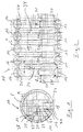
- Figure 1 shows a schematic cross-sectional view of a deflection compensating roller 10.
- This comprises a circumferential roller shell 12, a yoke 14 axially penetrating the roller shell 12 and several, each in the axial direction Hydrostatic and / or hydrodynamic support elements 16 (cf. also FIG. 2) which are at a distance a from one another and by means of which the roller jacket 12 is supported on the yoke 14 with the formation of an intermediate fluid cushion.
- the roller jacket 12 is rigid and can be displaced with respect to the yoke 14 parallel to the press plane P running through the support elements 16 and the axis of the deflection compensation roller 10.
- the deflection compensation roller 10 used as the top roller interacts with a bottom roller 18.
- a plurality of fluid wiping elements 20 distributed over the axial length of the roller shell 12 are provided on the inner circumference of the roller shell 12. These are arranged in a row parallel to the roll axis on the left side of the yoke 14 in FIG. 1 in the upper half of the roll.
- the distances a between the support elements 16 and, on the other hand, the distances b between the fluid wiping elements 20 are each the same, but the two values a and b are different.
- the axial length l of the fluid wiping elements 20, which are offset by half a pitch T of the support source arrangement with respect to the support sources 16, is somewhat larger in the present case than the distance a between the support elements 16.
- the piston-like support elements 16 are provided with hydrostatic pockets 24 which extend over the respective pressure chamber 26 (see FIG. 1) are fed, through which the relevant support element 16 can be acted upon.
- a fluid wiping element 20 is also provided between a respective axial end of the roller shell 12 and the adjacent support element 16. It can also be seen from FIG. 2 that the fluid wiping elements 20 act specifically on the fluid rings 34 formed by the support sources 16. These spread only slightly in the axial direction in the course of a roller revolution.
- the thickness of which can be, for example, in the range from 50 to 100 ⁇ m.
- the fluid wiping elements 16 are arranged, designed and / or acted on in such a way that they let through a respective fluid film with a thickness in the range of approximately 10 to 100 ⁇ m.
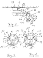
- FIG. 3 shows an embodiment variant of a fluid wiping element 20 which is arranged on an arm 34 of a two-armed lever 36 and is held against the inner surface of the roller shell 12 by the force of gravity G acting on the other lever arm 38.
- the two-armed lever 36 is over a joint 40 is attached to a support element 42, which in turn is attached to the yoke 14.
- the lever arm 38 is provided with an additional mass m at its end.
- the mass m provided at the end of the lever arm 38 causes the fluid wiping element 20 to be pivoted away in front of the inner surface of the roller shell 12 and thus remains ineffective.
- the pivot axis of the two-armed lever 36 defined by the joint 40 extends parallel to the roller axis.
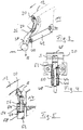
- FIG. 4 shows another embodiment variant of a fluid wiping element 20 which is pressed against the inner surface of the roll shell by spring force.
- the blade-like fluid wiping element 20 is preferably fastened to a plunger 44 which is pivotable about an axis B perpendicular to the roller axis and which is arranged in a guide sleeve 46, the bottom 48 of which it penetrates with its end facing away from the fluid wiping element 20.
- a compression spring 50 is inserted, which is pushed onto the plunger 44 and on the one hand on the bottom 48 of the guide sleeve 46 and on the other hand is supported on a widened extension 52 of the plunger 44, on which the blade-like fluid wiping element 20 is attached so as to be pivotable about the axis B.
- the compression spring 50 By means of the compression spring 50, the fluid wiping element 20 is thus pressed against the inner surface of the roll shell.
- the blade-like fluid scraper elements 20 can be slightly inclined with respect to the pressing plane P towards the inner circumference of the roll shell 12, as is shown in FIG. 1.
- the angle of inclination is about 33 °.
- the fluid wiping elements 20 are each provided with an inclined surface 28 facing the inner surface of the roller shell 12, through which there is a wedge gap between the inner circumference of the roller shell 12 and the respective fluid wiping element 20 held against it (see FIGS. 4 and 1).
- the fluid wiping elements 20 are only effective when the roller jacket 12 rotates in a direction R (see FIG. 1), while they allow fluid to pass through when the roller jacket 12 rotates in the opposite direction due to the hydrodynamic effect caused by the wedge gap.
- the deflection compensation roller in question is used in particular as an upper roller, in which the roller shell rotates in the direction designated by "R" in FIG. 1, so that the fluid wiping elements 20 are effective.
- these fluid wiping elements 20 let fluid pass through due to the hydrodynamic effect caused by the wedge gap between the inclined surface 28 and the roll casing.
- the fluid wiping elements 20 are, for example, resilient in the manner described against the inner surface of the Roll shell 12 held, they remain ineffective when using the deflection compensating roller 10 shown in Figure 1 as a lower roller, in which the direction of rotation of the roller shell 12 with respect to these fluid wiping elements 20 reverses.
- the deflection compensation roller 10 shown in FIGS. 1 and 2 can thus be used both as an upper roller and as a lower roller.
- the support elements 16 themselves serve as wiping elements.
- FIG. 4 two different positions of the fluid wiping element 20 are shown with solid and dashed lines, which result from a displacement of the roller shell relative to the yoke.
- two generally axially aligned rows of such wiping elements 20 can also be provided, whereby the fluid wiping elements 20 of the two rows with their inclined surfaces 28 are then arranged in different ways so that in one of them In the direction of the rotating roller jacket only the fluid wiping elements 20 of the one row and in the opposite direction rotating roller jacket only the fluid wiping elements 20 of the other row are effective.
- Such an arrangement of two rows of fluid wiping elements 20 is particularly advantageous in the case that the deflection compensation roller in question should be usable as a top roller for two sister machines in a mirror-inverted arrangement.
- the two rows of fluid wiping elements 20 are then arranged on opposite sides of the yoke.
- FIG. 5 shows a further embodiment variant of a fluid wiping element 20 with an associated piston / cylinder unit 54, by means of which it can be pressed against the inner surface of the roller shell 12.
- the fluid wiping element 20 is fastened to the outer end of a piston rod 56 so as to be pivotable about an axis A which extends at least substantially in the circumferential direction, to the other end of which the piston 60 provided in the cylinder 58 is fastened.
- the cylinder 58 is in turn firmly attached to the yoke 14.
- the piston 60 can be acted upon via the lower pressure chamber 62 of the cylinder 58 such that the fluid wiping element 20 is pressed against the inner surface of the roller shell 12 via the piston rod 56.
- a compression spring 64 is inserted, which is pushed onto the piston rod 56 and is supported on the one hand on the piston 60 and on the other hand on the upper end wall of the cylinder 58 provided with a through opening for the piston rod 56.
- Such a fluid wiping element 20 can thus also be controlled externally in particular.
- the force with which the fluid wiping element 20 is pressed against the inner surface of the roll shell 12 can also be adjusted or varied without any problems.
- the respective pressure spaces 62 are to be acted upon with a corresponding pressure fluid, whereupon the fluid wiping elements 20 are pressed against the force of the compression springs 64 on the roller shell 12. If, on the other hand, the fluid wiping elements 20 are to remain ineffective, for example when the deflection compensation roller is used as the lower roller, then the pressure spaces 62 are merely to be kept free of pressure or to be relieved.
- the compression springs 64 then ensure that the fluid wiping elements 20 are held at a sufficient distance from the inner surface of the roll shell 12.
- two rows of such fluid wiping elements 20, each generally axially formed, can also be provided instead of one.
- the two rows of fluid wiping elements are arranged on the two opposite sides of the yoke 14.
- Each row of fluid wiping elements 20 is in turn assigned at least one underlying fluid receptacle 22 in order to remove the fluid with the aid of gravity (cf. also FIG. 1).
- the deflection compensation rollers 10 shown in FIGS. 7 and 8 each serve as the top roller, which cooperates with a bottom roller 18 to form a respective press nip.
- the roller arrangements shown in FIGS. 7 and 8 are mirror-inverted arrangements, which means that the roller shell 12 in one case in one direction R, in FIG. 7 counterclockwise, and in the other case in the opposite direction R ', that is turns clockwise (see Figure 8).
- fluid is wiped off the inner surface of the roll shell 12 only by the left row of fluid wiping elements 20.
- the associated cylinder / piston units 54 are acted upon accordingly, so that the fluid wiping elements 20 counter to the force of the return springs be pressed against the roll shell 12.
- the fluid wiping elements 20 of the right row remain ineffective.
- the relevant cylinder / piston units 54 are therefore not acted upon, so that the fluid wiping elements 20 are held in the starting position by the force of the return springs, in which they are at a sufficient distance from the inner surface of the roller shell 12.
- the left fluid wiping elements 20 of the deflection compensation roller 10 which in turn is used as the top roller, remain ineffective.
- the relevant cylinder / piston units 54 are depressurized, so that the fluid wiping elements 20 are held by the compression springs in the starting position in which they are arranged at a distance from the inner surface of the roll shell 12.
- one and the same deflection compensation roller 10 can be used both for the arrangement according to FIG. 7 and for the arrangement according to FIG. 8. All that is required is a different control of the fluid wiping elements 20.
- the respective contact pressure can in turn be influenced from the outside.
- FIG. 6 shows a further embodiment of a fluid wiping element 20, which is arranged on an arm 34 of a two-armed lever 36 and is pressed against the inner surface of the roller shell 12 by the force of gravity acting on the other lever arm 38.
- the two-armed lever 36 is in turn attached via a joint 40 to a carrier element 42 fastened to the yoke.
- the pivot axis defined by the joint 40 no longer extends parallel, but perpendicular to the roller axis, i.e. in Figure 6 perpendicular to the plane of the drawing.
- the fluid wiping element 20 has a blade-like design and is also pivotably attached to the lever arm 34.
- the relevant pivot axis S also extends perpendicular to the roller axis and essentially in the circumferential direction.
- the free end of the lever arm 38 is in turn provided with a mass m in order to obtain the best possible gravity-assisted contact pressure.
- the lever 36 shown once with solid lines and once with dashed lines, is shown in two different pivot positions, which result from different positions of the roller shell 12 relative to the yoke.
- the fluid wiping element 20 lies completely against the inner surface of the roller shell 12, which is possible due to the mounting of the fluid wiping element 20 on the lever arm 34 which can be pivoted about the axis S.
- the mass m causes the fluid wiping element 20 to be pressed against the inner surface of the roller shell 12 by a corresponding pivoting of the lever 36.
- the lever 36 is pivoted when the roller is used as the lower roller due to the mass m so that the fluid wiping element 20 is held at a sufficient distance from the inner surface of the roller shell 12.
- the maximum stroke of the fluid wiping element 20 can be, for example, approximately 40 mm.
Landscapes
- Physics & Mathematics (AREA)
- Fluid Mechanics (AREA)
- Engineering & Computer Science (AREA)
- General Engineering & Computer Science (AREA)
- Mechanical Engineering (AREA)
- Rolls And Other Rotary Bodies (AREA)
- Paper (AREA)
- Machines For Manufacturing Corrugated Board In Mechanical Paper-Making Processes (AREA)
Applications Claiming Priority (2)
| Application Number | Priority Date | Filing Date | Title |
|---|---|---|---|
| DE19616802 | 1996-04-26 | ||
| DE19616802A DE19616802A1 (de) | 1996-04-26 | 1996-04-26 | Durchbiegungsausgleichswalze |
Publications (3)
| Publication Number | Publication Date |
|---|---|
| EP0803606A2 true EP0803606A2 (fr) | 1997-10-29 |
| EP0803606A3 EP0803606A3 (fr) | 1998-12-23 |
| EP0803606B1 EP0803606B1 (fr) | 2005-01-12 |
Family
ID=7792589
Family Applications (1)
| Application Number | Title | Priority Date | Filing Date |
|---|---|---|---|
| EP97102072A Expired - Lifetime EP0803606B1 (fr) | 1996-04-26 | 1997-02-10 | Rouleau à réglage de la flexion |
Country Status (6)
| Country | Link |
|---|---|
| US (1) | US5846173A (fr) |
| EP (1) | EP0803606B1 (fr) |
| JP (1) | JP4051101B2 (fr) |
| AT (1) | ATE287006T1 (fr) |
| CA (1) | CA2203327C (fr) |
| DE (2) | DE19616802A1 (fr) |
Families Citing this family (13)
| Publication number | Priority date | Publication date | Assignee | Title |
|---|---|---|---|---|
| FI2920U1 (fi) * | 1997-02-28 | 1997-05-29 | Valmet Corp | Järjestely kuormituskengillä varustetussa taipumakompensoidussa telassa |
| FI103071B1 (fi) * | 1997-08-19 | 1999-04-15 | Valmet Corp | Taivutettava tela rainamaista materiaalia varten |
| FI114334B (fi) * | 1998-09-23 | 2004-09-30 | Metso Paper Inc | Laitteisto taipumasäädettävän telan yhteydessä ja menetelmä öljyvirtauksen ohjauksessa taipumasäädettävän telan yhteydessä |
| DE19903843C1 (de) * | 1999-02-01 | 2000-07-06 | Voith Sulzer Papiertech Patent | Walze für eine Walzenmaschine |
| FI115790B (fi) * | 1999-07-06 | 2005-07-15 | Metso Paper Inc | Menetelmä ja sovitelma öljyn poistamiseksi taipumakompensoidusta telasta |
| US6921450B2 (en) * | 2001-10-31 | 2005-07-26 | Marquip, Llc | Soft contact roll for a single facer |
| DE10249483B4 (de) * | 2002-10-24 | 2005-05-19 | Voith Paper Patent Gmbh | Biegeausgleichswalze und Verfahren zum Betreiben einer Biegeausgleichswalze |
| JP2005221027A (ja) * | 2004-02-06 | 2005-08-18 | Mitsubishi Heavy Ind Ltd | ロール装置用油回収装置 |
| DE102005022065A1 (de) * | 2005-05-12 | 2006-11-16 | Voith Patent Gmbh | Presswalze |
| FI20065507L (fi) * | 2006-08-04 | 2008-02-05 | Metso Paper Inc | Paperi-/kartonkikoneen tai jälkikäsittelykoneen taipumakompensoitu tela |
| DE102006056695A1 (de) * | 2006-11-29 | 2008-06-05 | Andritz Küsters Gmbh | Kalander zur Behandlung einer Warenbahn |
| US20090045029A1 (en) * | 2007-08-16 | 2009-02-19 | Deur Delwyn G | Conveyor roller and cartridge bearing assembly for same |
| CN111173840B (zh) | 2015-06-30 | 2021-10-26 | 美国圣戈班性能塑料公司 | 滑动轴承 |
Family Cites Families (10)
| Publication number | Priority date | Publication date | Assignee | Title |
|---|---|---|---|---|
| CH606604A5 (fr) * | 1975-11-04 | 1978-11-15 | Escher Wyss Ag | |
| DE2744524C2 (de) * | 1977-10-04 | 1979-07-26 | Kuesters, Eduard, 4150 Krefeld | Walze für die Druckbehandlung von Warenbahnen |
| AT368563B (de) * | 1980-03-25 | 1982-10-25 | Escher Wyss Ag | Hydrostatisches stuetzelement, insbesondere fuer eine durchbiegungseinstellwalze zur druckbehandlung von materialbahnen, insbesondere papierbahnen |
| DE3528333A1 (de) * | 1985-08-07 | 1987-02-19 | Kuesters Eduard | Walze |
| FR2590650B1 (fr) * | 1985-11-22 | 1988-02-26 | Clecim Sa | Cylindre a frette tournante deformable notamment pour un laminoir |
| DE3813598C1 (fr) * | 1988-04-22 | 1989-11-23 | Eduard Kuesters, Maschinenfabrik, Gmbh & Co Kg, 4150 Krefeld, De | |
| DE3820974C3 (de) * | 1988-06-22 | 1996-03-21 | Kuesters Eduard Maschf | Dichtungsglied bzw. Walze |
| DE4123115A1 (de) * | 1991-07-12 | 1993-01-14 | Voith Gmbh J M | Hydrostatisch gestuetzte durchbiegungsausgleichswalze, insbesondere fuer papiermaschinen |
| US5189775A (en) * | 1992-02-25 | 1993-03-02 | The Black Clawson Company | Zone controlled deflection compensated roll |
| DE4420104C2 (de) * | 1994-06-09 | 1997-04-24 | Voith Sulzer Papiermasch Gmbh | Stützelement |
-
1996
- 1996-04-26 DE DE19616802A patent/DE19616802A1/de not_active Ceased
-
1997
- 1997-02-10 EP EP97102072A patent/EP0803606B1/fr not_active Expired - Lifetime
- 1997-02-10 AT AT97102072T patent/ATE287006T1/de not_active IP Right Cessation
- 1997-02-10 DE DE59712159T patent/DE59712159D1/de not_active Expired - Lifetime
- 1997-04-18 US US08/837,471 patent/US5846173A/en not_active Expired - Fee Related
- 1997-04-22 CA CA002203327A patent/CA2203327C/fr not_active Expired - Fee Related
- 1997-04-25 JP JP10852897A patent/JP4051101B2/ja not_active Expired - Fee Related
Also Published As
| Publication number | Publication date |
|---|---|
| DE59712159D1 (de) | 2005-02-17 |
| CA2203327C (fr) | 2006-09-19 |
| DE19616802A1 (de) | 1997-10-30 |
| EP0803606A3 (fr) | 1998-12-23 |
| EP0803606B1 (fr) | 2005-01-12 |
| ATE287006T1 (de) | 2005-01-15 |
| CA2203327A1 (fr) | 1997-10-26 |
| JPH1047339A (ja) | 1998-02-17 |
| JP4051101B2 (ja) | 2008-02-20 |
| US5846173A (en) | 1998-12-08 |
Similar Documents
| Publication | Publication Date | Title |
|---|---|---|
| DE69109324T2 (de) | Presswalze. | |
| EP0555752B1 (fr) | Outil de cintrage rotatif à graissage permanent | |
| DE3138365A1 (de) | Durchbiegungseinstellwalze | |
| EP0803606B1 (fr) | Rouleau à réglage de la flexion | |
| DE1461066B2 (de) | Walze fuer die druckbehandlung von papierbahnen | |
| DE3528333C2 (fr) | ||
| WO2003078077A1 (fr) | Systeme de dosage a racle | |
| DE4015245C2 (de) | Durchbiegungseinstellwalze | |
| DE102012001956A1 (de) | Beschichtungssystem für flexible Bahnen | |
| DE2001484A1 (de) | Hyd?atische Eno? fuer Pumpen und Motoren | |
| EP0840860B1 (fr) | Cylindre ou element de support d'un cylindre | |
| DE102012201378A1 (de) | Vorrichtung und Verfahren zur Anstellung einer Rakel an eine Mantelfläche einer rotierbaren Walze | |
| DE10045515B4 (de) | Rakel-Dosiersystem | |
| DE69604874T2 (de) | Stützvorrichtung für die Seitenwände einer Walzenstranggiessanlage zum Herstellen metallischer Bänder | |
| EP0812994B1 (fr) | Rouleau avec compensation de la déflection | |
| DE2838427A1 (de) | Walze fuer die druckbehandlung von materialbahnen, insbesondere papierbahnen | |
| DE19523828C1 (de) | Hydraulische Axialkolbenmaschine | |
| DE3011669C2 (de) | Preßwalze mit einer Einrichtung zum Korrigieren der Durchbiegung des Walzenmantels | |
| CH626959A5 (fr) | ||
| DE3637108A1 (de) | Pressenwalze, die insbesondere zur behandlung einer papierbahn oder dergleichen dient | |
| DE2831142C2 (de) | Durchbiegungseinstellwalze | |
| DE69924466T2 (de) | Abstreifvorrichtung für flüssigkeiten | |
| DE2905543C2 (de) | Walze für die Druckbehandlung von Warenbahnen | |
| DE4440267A1 (de) | Verfahren zur Steuerung einer Walze | |
| DE2801363A1 (de) | Anordnung bei einem schraubenkompressor zur herabsetzung der axialkraft |
Legal Events
| Date | Code | Title | Description |
|---|---|---|---|
| PUAI | Public reference made under article 153(3) epc to a published international application that has entered the european phase |
Free format text: ORIGINAL CODE: 0009012 |
|
| AK | Designated contracting states |
Kind code of ref document: A2 Designated state(s): AT DE FI SE |
|
| PUAL | Search report despatched |
Free format text: ORIGINAL CODE: 0009013 |
|
| AK | Designated contracting states |
Kind code of ref document: A3 Designated state(s): AT DE FI SE |
|
| RAP1 | Party data changed (applicant data changed or rights of an application transferred) |
Owner name: VOITH SULZER PAPIERTECHNIK PATENT GMBH |
|
| 17P | Request for examination filed |
Effective date: 19990623 |
|
| RAP1 | Party data changed (applicant data changed or rights of an application transferred) |
Owner name: VOITH PAPER PATENT GMBH |
|
| GRAP | Despatch of communication of intention to grant a patent |
Free format text: ORIGINAL CODE: EPIDOSNIGR1 |
|
| GRAS | Grant fee paid |
Free format text: ORIGINAL CODE: EPIDOSNIGR3 |
|
| GRAA | (expected) grant |
Free format text: ORIGINAL CODE: 0009210 |
|
| AK | Designated contracting states |
Kind code of ref document: B1 Designated state(s): AT DE FI SE |
|
| REF | Corresponds to: |
Ref document number: 59712159 Country of ref document: DE Date of ref document: 20050217 Kind code of ref document: P |
|
| REG | Reference to a national code |
Ref country code: SE Ref legal event code: TRGR |
|
| PLBE | No opposition filed within time limit |
Free format text: ORIGINAL CODE: 0009261 |
|
| STAA | Information on the status of an ep patent application or granted ep patent |
Free format text: STATUS: NO OPPOSITION FILED WITHIN TIME LIMIT |
|
| 26N | No opposition filed |
Effective date: 20051013 |
|
| PGFP | Annual fee paid to national office [announced via postgrant information from national office to epo] |
Ref country code: AT Payment date: 20100212 Year of fee payment: 14 |
|
| PGFP | Annual fee paid to national office [announced via postgrant information from national office to epo] |
Ref country code: SE Payment date: 20110214 Year of fee payment: 15 |
|
| PG25 | Lapsed in a contracting state [announced via postgrant information from national office to epo] |
Ref country code: AT Free format text: LAPSE BECAUSE OF NON-PAYMENT OF DUE FEES Effective date: 20110210 |
|
| PG25 | Lapsed in a contracting state [announced via postgrant information from national office to epo] |
Ref country code: SE Free format text: LAPSE BECAUSE OF NON-PAYMENT OF DUE FEES Effective date: 20120211 |
|
| PGFP | Annual fee paid to national office [announced via postgrant information from national office to epo] |
Ref country code: FI Payment date: 20130213 Year of fee payment: 17 Ref country code: DE Payment date: 20130219 Year of fee payment: 17 |
|
| REG | Reference to a national code |
Ref country code: DE Ref legal event code: R119 Ref document number: 59712159 Country of ref document: DE |
|
| PG25 | Lapsed in a contracting state [announced via postgrant information from national office to epo] |
Ref country code: FI Free format text: LAPSE BECAUSE OF NON-PAYMENT OF DUE FEES Effective date: 20140210 |
|
| REG | Reference to a national code |
Ref country code: DE Ref legal event code: R119 Ref document number: 59712159 Country of ref document: DE Effective date: 20140902 |
|
| PG25 | Lapsed in a contracting state [announced via postgrant information from national office to epo] |
Ref country code: DE Free format text: LAPSE BECAUSE OF NON-PAYMENT OF DUE FEES Effective date: 20140902 |