EP0803426B1 - Running gear, especially bogie - Google Patents
Running gear, especially bogie Download PDFInfo
- Publication number
- EP0803426B1 EP0803426B1 EP96106712A EP96106712A EP0803426B1 EP 0803426 B1 EP0803426 B1 EP 0803426B1 EP 96106712 A EP96106712 A EP 96106712A EP 96106712 A EP96106712 A EP 96106712A EP 0803426 B1 EP0803426 B1 EP 0803426B1
- Authority
- EP
- European Patent Office
- Prior art keywords
- car body
- guide rods
- connecting rods
- rods
- body according
- Prior art date
- Legal status (The legal status is an assumption and is not a legal conclusion. Google has not performed a legal analysis and makes no representation as to the accuracy of the status listed.)
- Expired - Lifetime
Links
Images
Classifications
-
- B—PERFORMING OPERATIONS; TRANSPORTING
- B61—RAILWAYS
- B61F—RAIL VEHICLE SUSPENSIONS, e.g. UNDERFRAMES, BOGIES OR ARRANGEMENTS OF WHEEL AXLES; RAIL VEHICLES FOR USE ON TRACKS OF DIFFERENT WIDTH; PREVENTING DERAILING OF RAIL VEHICLES; WHEEL GUARDS, OBSTRUCTION REMOVERS OR THE LIKE FOR RAIL VEHICLES
- B61F5/00—Constructional details of bogies; Connections between bogies and vehicle underframes; Arrangements or devices for adjusting or allowing self-adjustment of wheel axles or bogies when rounding curves
- B61F5/38—Arrangements or devices for adjusting or allowing self- adjustment of wheel axles or bogies when rounding curves, e.g. sliding axles, swinging axles
-
- B—PERFORMING OPERATIONS; TRANSPORTING
- B61—RAILWAYS
- B61F—RAIL VEHICLE SUSPENSIONS, e.g. UNDERFRAMES, BOGIES OR ARRANGEMENTS OF WHEEL AXLES; RAIL VEHICLES FOR USE ON TRACKS OF DIFFERENT WIDTH; PREVENTING DERAILING OF RAIL VEHICLES; WHEEL GUARDS, OBSTRUCTION REMOVERS OR THE LIKE FOR RAIL VEHICLES
- B61F5/00—Constructional details of bogies; Connections between bogies and vehicle underframes; Arrangements or devices for adjusting or allowing self-adjustment of wheel axles or bogies when rounding curves
- B61F5/02—Arrangements permitting limited transverse relative movements between vehicle underframe or bolster and bogie; Connections between underframes and bogies
- B61F5/16—Centre bearings or other swivel connections between underframes and bolsters or bogies
Definitions
- the invention relates to a car body with a chassis with at least one sprung axle or Shaft, especially bogie, for rail vehicles, such as. B. funiculars.
- Such trolleys are known from WO 89/12566 and EP 0365 489 A2 and have the disadvantage that heavy bogie frames are required, and that for comfortable cross suspension and complicated for self-steering of the axles Devices must be arranged. Lead with poor substructure Deviations from the ideal rail position for bogie deformation or reduced driving comfort and increased wear.
- the invention has set itself the task of the disadvantages mentioned encounter and create a lightweight design for chassis. Due to the Use of radially displaceable spring-damper elements, which are the side or above the wheels, the vertical forces are directly in the Carriage body or directed into the bogie frame. With the spring-damper elements it is preferably air springs. The longitudinal and lateral forces are suspended or damped handlebars in the central pivot or headed directly into the car body. A major advantage is that the invention both the longitudinal and the transverse forces or their resilient Effects are dampened.
- the invention is characterized in that the axis / s or shaft / s by Handlebars arranged radially around a pivot point connected to the car body is / are and that the running axis / n or shaft / n through preferably parallel to the track arranged connecting rods with the car body or with each other is / are connected, whereby horizontal forces corresponding to the execution of the Handlebars and connecting rods in the arranged on the car body Pivot are guided undamped or initiated and that the vertical support of the wheels against the car body over the Barrel or shaft or the connecting rods or over the handlebars Spring elements, preferably air springs.
- Other essential features of the invention are specified in subclaims 2 - 8.
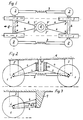
- Fig. 1 and 2 shows a bogie in elevation and plan
- Fig. 3 the Elevation of an axle undercarriage.
- Fig. 1 shows in plan a bogie of a rail vehicle in which the individual running axles 6 via damped or sprung in the axial direction Handlebar 4 are connected to the pivot 5 of the bogie.
- the handlebars 4 are optionally sprung and / or damped in the axial direction and have if necessary, at their connections to the individual components 6 and 5 elastic eyes 7, 7 'or are the bolt connections in elastic sleeves stored so that slight deformations within the connection during the Driving can be compensated.
- the handlebars 4 can also be used as shock absorbers be trained.
- the wheels 1 of the axes 6 are in the vertical direction Spring-damper elements 2 (Fig. 2) which are designed, for example, as an air spring are supported.
- the single ones Wheels 1 consecutive wheels 6 are by a resilient and / or damped Connecting rod 3 connected, for example, by a telescopic tube, in particular in suspended and / or damped in the axial direction, or a connecting rod with at least an elastically lined eye is formed.
- Both the connecting rods 3 and the links 4 are arranged in pairs, the links 4 being inclined to one another in plan otherwise essentially parallel and the connecting rods 3 of the axes 6 to each other are provided in parallel, in particular in the direction of travel 8.
- the handlebars 4 are fastened to a sleeve 10 which surrounds the component 5 in the form of a pivot vertical direction on component 5 is vertically displaceable, so that the car weight only is introduced into the chassis via the springs 2.
- both the connecting rods 3 and the handlebar 4 of rigid elements are formed that have little freedom of movement at the support point exhibit.
- at least one of the components 3 or 4 is preferably made with elastic Lanyards stored, or designed directly as a telescope, which means longer spring travel be made possible. In most cases, the lining of the eyes with one is sufficient elastic mass.
- the handlebars 4 and / or the connecting rods 3 as a telescopic damper element can be changed by changing the hydraulic pressure in the individual damper elements influence the spring stiffness or damper constant, so that the inclination of the car body can be influenced during rapid cornering, for example by reducing the hydraulic pressure on the inside of the curve and on the Outside the curve is increased compared to normal pressure.
- These measures can increase the maximum cornering speed.
- the use is essential to the invention of radially displaceable springs, preferably of air springs which move laterally or over the Wheels are arranged.
- the arrangement of the handlebars in a triangle to the central pivot point essential, the handlebars can also be unsprung, for example the connecting bolts are stored in elastic sleeves.
- the construction is not limited to the use of a bogie, it can also be used uniaxial trolleys (Fig. 3) are used, in which the handlebars 4 at one central point in the car body 9 and the half connecting rods 3 between the car body 9 and axis 6 are articulated. These measures equalize the Barrel axis 6 to the rail conditions without major deformations in the car body or introduced into the chassis frame.
- the invention enables a defined radial self-steering axis adjustment depending on of the existing transverse force using spring-loaded and possibly damped Connecting rods 3 and the handlebar assembly described above.
Abstract
Description
Die Erfindung betrifft einen Wagenaufbau mit einem Fahrwerk mit mindestens einer gefederten Laufachse oder Welle, insbesondere Drehgestell, für Schienenfahrzeuge, wie z. B. Standseilbahnen. Derartige Fahrwerke sind aus der WO 89/12566 bzw.EP 0365 489 A2 bekannt und haben den Nachteil, daß schwere Drehgestellrahmen benötigt werden, und daß für eine komfortable Querfederung und für ein Selbstlenken der Achsen komplizierte Vorrichtungen angeordnet werden müssen. Bei schlechtem Unterbau führen Abweichungen von der idealen Schienenlage zur Drehgestellverformung bzw. zu vermindertem Fahrkomfort und erhöhtem Verschleiß.The invention relates to a car body with a chassis with at least one sprung axle or Shaft, especially bogie, for rail vehicles, such as. B. funiculars. Such trolleys are known from WO 89/12566 and EP 0365 489 A2 and have the disadvantage that heavy bogie frames are required, and that for comfortable cross suspension and complicated for self-steering of the axles Devices must be arranged. Lead with poor substructure Deviations from the ideal rail position for bogie deformation or reduced driving comfort and increased wear.
Die Erfindung hat es sich zur Aufgabe gestellt, den genannten Nachteilen zu begegnen und eine leichte Bauweise für Fahrwerke zu schaffen. Aufgrund der Verwendung von radial verschieblichen Feder-Dämpfer-Elementen, welche sich seitlich bzw. über den Rädern befinden, werden die Vertikalkräfte direkt in den Wagenaufbau bzw. in den Drehgestellrahmen geleitet. Bei den Feder-Dämpfer-Elementen handelt es sich vorzugsweise um Luftfedern. Die Längs- und Querkräfte werden über gefederte bzw. gedämpfte Lenker in den zentralen Drehpunkt bzw. direkt in den Wagenaufbau geleitet. Ein wesentlicher Vorteil besteht darin, daß bei der Erfindung sowohl die Längs- als auch die Querkräfte bzw. ihre federnden Auswirkungen gedämpft werden.The invention has set itself the task of the disadvantages mentioned encounter and create a lightweight design for chassis. Due to the Use of radially displaceable spring-damper elements, which are the side or above the wheels, the vertical forces are directly in the Carriage body or directed into the bogie frame. With the spring-damper elements it is preferably air springs. The longitudinal and lateral forces are suspended or damped handlebars in the central pivot or headed directly into the car body. A major advantage is that the invention both the longitudinal and the transverse forces or their resilient Effects are dampened.
Die Erfindung ist dadurch gekennzeichnet, daß die Laufachse/n oder Welle/n durch radial um einen Drehpunkt angeordnete Lenker mit dem Wagenaufbau verbunden ist/sind und daß die Laufachse/n oder Welle/n durch vorzugsweise parallel zur Spur angeordnete Verbindungsstangen mit dem Wagenaufbau bzw. untereinander verbunden ist/sind, wodurch Horizontalkräfte entsprechend der Ausführung der Lenker und der Verbindungsstangen in den am Wagenaufbau angeordneten Drehpunkt ungedämpft geführt oder gedämpft eingeleitet werden und daß die vertikale Abstützung der Laufräder gegenüber dem Wagenaufbau über die Laufachse bzw. Welle oder die Verbindungsstangen oder über die Lenker über Federelemente, vorzugsweise Luftfedern, erfolgt. Weitere wesentliche Erfindungsmerkmale sind in den Unteransprüchen 2 - 8 angegeben.The invention is characterized in that the axis / s or shaft / s by Handlebars arranged radially around a pivot point connected to the car body is / are and that the running axis / n or shaft / n through preferably parallel to the track arranged connecting rods with the car body or with each other is / are connected, whereby horizontal forces corresponding to the execution of the Handlebars and connecting rods in the arranged on the car body Pivot are guided undamped or initiated and that the vertical support of the wheels against the car body over the Barrel or shaft or the connecting rods or over the handlebars Spring elements, preferably air springs. Other essential features of the invention are specified in subclaims 2 - 8.
Die Erfindung ist in der angeschlossenen Fig. 1-3 beispielsweise und schematisch dargestellt. Fig. 1 und 2 zeigt ein Drehgestell im Auf- und Grundriß und Fig. 3 den Aufriß eines Achsfahrwerkes.The invention is for example and schematically in the connected Fig. 1-3 shown. Fig. 1 and 2 shows a bogie in elevation and plan and Fig. 3 the Elevation of an axle undercarriage.
Fig. 1 zeigt im Grundriß ein Drehgestell eines Schienenfahrzeuges bei dem die
einzelnen Laufachsen 6 über in Achsrichtung gedämpft oder gefedert angeordnete
Lenker 4 mit dem Drehzapfen 5 des Drehgestelles verbunden sind. Die Lenker 4
sind wahlweise in Achsrichtung gefedert und/oder gedämpft und haben
gegebenenfalls an ihren Verbindungen zu den einzelnen Bauteilen 6 und 5
elastische Augen 7, 7' bzw. sind die Bolzenverbindungen in elastischen Hülsen
gelagert, sodaß geringfügige Verformungen innerhalb der Verbindung während des
Fahrens ausgeglichen werden können. Die Lenker 4 können auch als Stoßdämpfer
ausgebildet sein. Die Laufräder 1 der Laufachsen 6 sind in vertikaler Richtung durch
Feder-Dämpfer-Elemente 2 (Fig. 2) die beispielsweise als Luftfeder ausgebildet
sind, abgestützt. Die einzelnen
Laufräder 1 aufeinanderfolgender Laufachsen 6 sind durch eine federnde und/oder gedämpfte
Verbindungsstange 3 verbunden, die beispielsweise von einem Teleskoprohr, insbesondere in
in Achsrichtung gefedert und/oder gedämpft, bzw. einer Verbindungsstange mit mindestens
einem elastisch ausgekleidetem Auge gebildet ist. Sowohl die Verbindungsstangen 3 als auch
die Lenker 4 sind paarweise angeordnet, wobei die Lenker 4 im Grundriß zueinander geneigt
sonst im wesentlichen parallel und die Verbindungsstangen 3 der Laufachsen 6 zueinander
parallel, insbesondere in Fahrrichtung 8, vorgesehen sind. Durch diese Maßnahmen wird
praktisch eine Einzelradfederung in einem Drehgestell erreicht, sodaß Ungenauigkeiten im
Schienenaufbau bzw. durch schlechten Unterbau ausgeglichen werden können.Fig. 1 shows in plan a bogie of a rail vehicle in which the
individual running axles 6 via damped or sprung in the axial direction
Handlebar 4 are connected to the
Um Zwangsspannungen in den Lenkern 4 auszuschalten, sind in einer optimalen Ausführung
die Lenker 4 an einer Hülse 10 befestigt, die um den als Drehzapfen ausgebildeten Bauteil 5 in
vertikaler Richtung an Bauteil 5 vertikal verschiebbar gelagert ist, sodaß das Wagengewicht nur
über die Federn 2 in das Fahrwerk eingebracht wird.In order to switch off forced voltages in the
Im Rahmen der Erfindung können sowohl die Verbindungsstangen 3 als auch die Lenker 4 von
starren Elementen gebildet werden, die an der Auflagerstelle geringe Beweglichkeitsfreiheiten
aufweisen. Vorzugsweise wird jedoch mindestens einer der Bauteile 3 oder 4 mit elastischen
Verbindungsmitteln gelagert, oder direkt als Teleskop ausgebildet, wodurch größere Federwege
ermöglicht werden. In den meisten Fällen genügt die Auskleidung der Augen mit einer
elastischen Masse. Im Falle der Ausbildung der Lenker 4 und/oder der Verbindungsstangen 3
als teleskopierbares Dämpferelement läßt sich durch Veränderung des Hydraulikdruckes in den
einzelnen Dämpfer-Elementen die Federsteifigkeit bzw. Dämpferkonstante beeinflussen, sodaß
bei raschen Kurvenfahrten die Schrägstellung des Wagenkastens beeinflußt werden kann,
indem beispielsweise der Hydraulikdruck auf der Kurveninnenseite erniedrigt und auf der
Kurvenaußenseite gegenüber dem Normaldruck erhöht wird. Durch diese Maßnahmen läßt sich
die maximale Kurvengeschwindigkeit erhöhen. Wesentlich für die Erfindung ist die Verwendung
von radial verschiebbaren Federn vorzugsweise von Luftfedern, welche seitlich bzw. über den
Rädern angeordnet sind. Ferner ist die Anordnung der Lenker im Dreieck zum zentralen Drehpunkt
wesentlich, wobei die Lenker auch ungefedert ausgebildet sein können, indem beispielsweise
die Anschlußbolzen in elastischen Hülsen gelagert sind.In the context of the invention, both the connecting
Die Konstruktion ist nicht auf die Verwendung eines Drehgestells beschränkt, sie kann auch bei
einachsigen Fahrwerken (Fig. 3) verwendet werden, bei welchen die Lenker 4 an einem
zentralen Punkt im Wagenaufbau 9 und die halben Verbindungsstangen 3 zwischen Wagenaufbau
9 und Laufachse 6 gelenkig angeordnet sind. Durch diese Maßnahmen gleicht sich die
Laufachse 6 den Schienengegebenheiten an, ohne daß größere Verformungen in den Wagenkasten
bzw. in den Fahrgestellrahmen eingeleitet werden. The construction is not limited to the use of a bogie, it can also be used
uniaxial trolleys (Fig. 3) are used, in which the
Die Erfindung ermöglicht eine definierte radiale selbstlenkende Achseinstellung in Abhängigkeit
von der vorhandenen Querkraft unter Verwendung von gefederten und eventuell gedämpften
Verbindungsstangen 3 und der oben beschriebenen Lenkeranordnung. Es besteht die Möglichkeit
der Überlagerung der radialen Achseinstellung durch entsprechende Steuerung der Lenker
bzw. Verbindungsstangen. Aufgrund der symmetrischen Bauweise lassen sich die gleichen Bauteile
sowohl für ein Drehgestell (mit zwei Laufachsen) als auch für ein Achsfahrwerk (mit einer
Achse) verwenden, wobei beim Letzteren die halbierten Verbindungsstangen mit dem Wagenkasten
bzw. dem Fahrgestellrahmen gelenkig verbunden werden.The invention enables a defined radial self-steering axis adjustment depending on
of the existing transverse force using spring-loaded and possibly damped
Connecting
Claims (8)
- A car body comprising a running gear that includes at least one spring-suspended running axle (6) or shaft, especially bogie, for rail vehicles, such as cableways, characterised in that said running axle(s) (6) or shaft(s) is/are connected to said car body (9) or is/are interconnected by guide rods situated radially about a pivot point (5), and that said running axle(s) (6) or shaft(s) is/are connected to said car body (9) or is/are interconnected by connecting rods (3) which preferably extend parallely to the track whereby horizontal forces are either passed undamped or lead into said pivoting point (5) located on said car body (9) in a damped manner according to the construction of said guide rods (4) and connecting rods (3), and that the vertical support of the travelling wheels with respect to said car body (9) is effected by resilient elements, preferably pneumatic cushioning, via said running axle (6) or shaft or said connecting rods (3) or said guide rods (4).
- Car body according to claim 1, characterised in that said guide rods (4)for each running axle (6) are inclined towards each other in pairs symmetrically to the vehicle axis, a plurality of them being optionally superposed or adjacent to each other, the guide rods (4), in case of a plurality of them, being preferably situated parallel, but also under an angle.
- Car body according to claim 1, characterised in that said guide rods (4) are elastic and/or dampened in axial direction.
- Car body according to claim 1, characterised in that said connecting rods (3) are elastic and/or dampened in axial direction.
- Car body according to claim 1, characterised in that said guide rods (4)and said connecting rods (3) are arranged so as to be elastic and/or damped.
- Car body according to claim 1, characterised in that at least part of said guide rods and connecting rods (3 and 4) are comprised with controllable elasticity or dampening symmetrically to the direction of journey (8) so that, for example, the axle position of the rail vehicle, in the case of different bend radius' of the rails, is controllable by varying the hydraulic pressure in the individual guide rods and connecting rods (3, 4).
- Car body according to claim 1, characterised in that said guide rods (4) are born on a sleeve (10) about the component (5) formed as a journal, and that said sleeve (10) is moveably guided in vertical direction on said journal.
- Car body according to claim 1, characterised in that pivoting of said running axle (6) with respect to said car body (9) is damped by arranging a shock-absorber between said running axle (6) or connecting rod (3) or guide rod (4) and said car body (9) which acts on a lever arm with respect to said pivot point (5).
Priority Applications (4)
| Application Number | Priority Date | Filing Date | Title |
|---|---|---|---|
| DE59604686T DE59604686D1 (en) | 1996-04-27 | 1996-04-27 | Chassis, especially bogie |
| AT96106712T ATE190574T1 (en) | 1996-04-27 | 1996-04-27 | CHASSIS, ESPECIALLY BOGIE |
| EP96106712A EP0803426B1 (en) | 1996-04-27 | 1996-04-27 | Running gear, especially bogie |
| ES96106712T ES2145950T3 (en) | 1996-04-27 | 1996-04-27 | ROLLED TRAIN, ESPECIALLY FOR VEHICLES ON RAILS. |
Applications Claiming Priority (1)
| Application Number | Priority Date | Filing Date | Title |
|---|---|---|---|
| EP96106712A EP0803426B1 (en) | 1996-04-27 | 1996-04-27 | Running gear, especially bogie |
Publications (2)
| Publication Number | Publication Date |
|---|---|
| EP0803426A1 EP0803426A1 (en) | 1997-10-29 |
| EP0803426B1 true EP0803426B1 (en) | 2000-03-15 |
Family
ID=8222726
Family Applications (1)
| Application Number | Title | Priority Date | Filing Date |
|---|---|---|---|
| EP96106712A Expired - Lifetime EP0803426B1 (en) | 1996-04-27 | 1996-04-27 | Running gear, especially bogie |
Country Status (4)
| Country | Link |
|---|---|
| EP (1) | EP0803426B1 (en) |
| AT (1) | ATE190574T1 (en) |
| DE (1) | DE59604686D1 (en) |
| ES (1) | ES2145950T3 (en) |
Families Citing this family (4)
| Publication number | Priority date | Publication date | Assignee | Title |
|---|---|---|---|---|
| DK1226058T3 (en) * | 1999-11-03 | 2004-07-26 | Andreas Schaefer-Enkeler | Bogie for rail vehicles |
| DE102007025163A1 (en) * | 2007-05-29 | 2008-12-04 | Bombardier Transportation Gmbh | Rail vehicle with single-stage suspension |
| PL224900B1 (en) * | 2013-10-15 | 2017-02-28 | Politechnika Warszawska | System of wheel sets linkage of the course-keeping carriage |
| TWI581995B (en) * | 2014-07-31 | 2017-05-11 | Nippon Steel & Sumitomo Metal Corp | Railway vehicle trolley and railway vehicle with the trolley |
Family Cites Families (4)
| Publication number | Priority date | Publication date | Assignee | Title |
|---|---|---|---|---|
| US2861522A (en) * | 1956-11-13 | 1958-11-25 | Transit Res Corp | Light-weight rail truck |
| GB1306080A (en) * | 1969-10-13 | 1973-02-07 | ||
| DE3706180A1 (en) * | 1987-02-26 | 1988-09-08 | Messerschmitt Boelkow Blohm | CHASSIS FOR A RAIL VEHICLE |
| FI82424C (en) * | 1989-05-24 | 1991-03-11 | Valmet Oy | BOGGIEKONSTRUKTION FOER JAERNVAEGSVAGN. |
-
1996
- 1996-04-27 AT AT96106712T patent/ATE190574T1/en active
- 1996-04-27 EP EP96106712A patent/EP0803426B1/en not_active Expired - Lifetime
- 1996-04-27 ES ES96106712T patent/ES2145950T3/en not_active Expired - Lifetime
- 1996-04-27 DE DE59604686T patent/DE59604686D1/en not_active Expired - Fee Related
Also Published As
| Publication number | Publication date |
|---|---|
| ATE190574T1 (en) | 2000-04-15 |
| DE59604686D1 (en) | 2000-04-20 |
| ES2145950T3 (en) | 2000-07-16 |
| EP0803426A1 (en) | 1997-10-29 |
Similar Documents
| Publication | Publication Date | Title |
|---|---|---|
| EP0031008B1 (en) | Bogie for rail vehicles | |
| EP0565676B1 (en) | Running gear for low-platform waggons | |
| EP1610995B1 (en) | Running gear for a railway vehicle provided with an improved transversal suspension | |
| EP0017856B1 (en) | Suspension for transport means | |
| DE4311521C1 (en) | Support against unsteadiness in rail vehicle - has cross inclination control with length-alterable, adjustable connecting piece controlled by drive component | |
| EP0547188B1 (en) | Bogie for high-speed railway vehicles | |
| DE2027885A1 (en) | Axle suspension, in particular rear axle suspension for motor vehicles | |
| DE19826448C2 (en) | Running gear for a rail vehicle | |
| DE2142523A1 (en) | WHEEL SUSPENSION FOR VEHICLES, IN PARTICULAR MOTOR VEHICLES | |
| EP1592570B1 (en) | Wheel suspension for motor vehicles | |
| CH676220A5 (en) | ||
| EP0598353B1 (en) | Running gear for low-platform trains | |
| EP0649782B1 (en) | Railway vehicle and railway train for such a vehicle | |
| EP0016469B1 (en) | Device for resiliently supporting a torsionally rigid superstructure on a torsionally yieldable chassis frame of load-carrying vehicles | |
| DE102017200006A1 (en) | Neige vehicle | |
| EP0803426B1 (en) | Running gear, especially bogie | |
| AT404010B (en) | Truck, in particular pivoted bogie for a rail vehicle such as the wagon of a funicular railway | |
| EP0439574B1 (en) | Driven running gear with steerable individual units | |
| EP0507146B1 (en) | Railway vehicle especially low floor vehicle | |
| DE4214066A1 (en) | Bogie for rail vehicle - consists of independent struts, connected by coupling member, with individual wheels suspended from strut ends via primary springs | |
| DE1010092B (en) | Drive arrangement for a rail articulated train | |
| EP2803514A1 (en) | Suspension device | |
| DE1138645B (en) | Rear suspension, especially for motor vehicles | |
| DE3742599A1 (en) | Device for adjusting the height of a vehicle wheel | |
| EP1277603A2 (en) | Multi link independent wheel suspension, in particular suspension of a steerable front wheel of a motor vehicle |
Legal Events
| Date | Code | Title | Description |
|---|---|---|---|
| PUAI | Public reference made under article 153(3) epc to a published international application that has entered the european phase |
Free format text: ORIGINAL CODE: 0009012 |
|
| AK | Designated contracting states |
Kind code of ref document: A1 Designated state(s): AT CH DE ES FR IT LI |
|
| 17P | Request for examination filed |
Effective date: 19970909 |
|
| 17Q | First examination report despatched |
Effective date: 19981210 |
|
| GRAG | Despatch of communication of intention to grant |
Free format text: ORIGINAL CODE: EPIDOS AGRA |
|
| GRAG | Despatch of communication of intention to grant |
Free format text: ORIGINAL CODE: EPIDOS AGRA |
|
| GRAG | Despatch of communication of intention to grant |
Free format text: ORIGINAL CODE: EPIDOS AGRA |
|
| GRAH | Despatch of communication of intention to grant a patent |
Free format text: ORIGINAL CODE: EPIDOS IGRA |
|
| GRAH | Despatch of communication of intention to grant a patent |
Free format text: ORIGINAL CODE: EPIDOS IGRA |
|
| GRAA | (expected) grant |
Free format text: ORIGINAL CODE: 0009210 |
|
| RAP1 | Party data changed (applicant data changed or rights of an application transferred) |
Owner name: LEITNER AUSTRIA GMBH |
|
| AK | Designated contracting states |
Kind code of ref document: B1 Designated state(s): AT CH DE ES FR IT LI |
|
| REF | Corresponds to: |
Ref document number: 190574 Country of ref document: AT Date of ref document: 20000415 Kind code of ref document: T |
|
| REG | Reference to a national code |
Ref country code: CH Ref legal event code: NV Representative=s name: ISLER & PEDRAZZINI AG Ref country code: CH Ref legal event code: EP |
|
| RAP2 | Party data changed (patent owner data changed or rights of a patent transferred) |
Owner name: LEITNER INTERNATIONAL B.V. |
|
| REF | Corresponds to: |
Ref document number: 59604686 Country of ref document: DE Date of ref document: 20000420 |
|
| ET | Fr: translation filed | ||
| ITF | It: translation for a ep patent filed |
Owner name: MODIANO & ASSOCIATI S.R.L. |
|
| REG | Reference to a national code |
Ref country code: ES Ref legal event code: FG2A Ref document number: 2145950 Country of ref document: ES Kind code of ref document: T3 |
|
| REG | Reference to a national code |
Ref country code: CH Ref legal event code: PFA Free format text: LEITNER INTERNATIONAL B.V. TRANSFER- HIGH TECHNOLOGY INVESTMENTS B.V. |
|
| PLBE | No opposition filed within time limit |
Free format text: ORIGINAL CODE: 0009261 |
|
| STAA | Information on the status of an ep patent application or granted ep patent |
Free format text: STATUS: NO OPPOSITION FILED WITHIN TIME LIMIT |
|
| REG | Reference to a national code |
Ref country code: FR Ref legal event code: CD |
|
| REG | Reference to a national code |
Ref country code: ES Ref legal event code: PC2A |
|
| 26N | No opposition filed | ||
| REG | Reference to a national code |
Ref country code: CH Ref legal event code: PCAR Free format text: ISLER & PEDRAZZINI AG;POSTFACH 1772;8027 ZUERICH (CH) |
|
| PGFP | Annual fee paid to national office [announced via postgrant information from national office to epo] |
Ref country code: DE Payment date: 20090629 Year of fee payment: 14 |
|
| PG25 | Lapsed in a contracting state [announced via postgrant information from national office to epo] |
Ref country code: DE Free format text: LAPSE BECAUSE OF NON-PAYMENT OF DUE FEES Effective date: 20101103 |
|
| REG | Reference to a national code |
Ref country code: FR Ref legal event code: PLFP Year of fee payment: 20 |
|
| PGFP | Annual fee paid to national office [announced via postgrant information from national office to epo] |
Ref country code: ES Payment date: 20150310 Year of fee payment: 20 |
|
| PGFP | Annual fee paid to national office [announced via postgrant information from national office to epo] |
Ref country code: CH Payment date: 20150414 Year of fee payment: 20 |
|
| PGFP | Annual fee paid to national office [announced via postgrant information from national office to epo] |
Ref country code: FR Payment date: 20150408 Year of fee payment: 20 Ref country code: AT Payment date: 20150325 Year of fee payment: 20 Ref country code: IT Payment date: 20150422 Year of fee payment: 20 |
|
| REG | Reference to a national code |
Ref country code: CH Ref legal event code: PL |
|
| REG | Reference to a national code |
Ref country code: AT Ref legal event code: MK07 Ref document number: 190574 Country of ref document: AT Kind code of ref document: T Effective date: 20160427 |
|
| REG | Reference to a national code |
Ref country code: ES Ref legal event code: FD2A Effective date: 20160803 |
|
| PG25 | Lapsed in a contracting state [announced via postgrant information from national office to epo] |
Ref country code: ES Free format text: LAPSE BECAUSE OF EXPIRATION OF PROTECTION Effective date: 20160428 |