EP0803380A1 - Identifizierungsetikettenhalter und Hängeordner mit einem solchen Halter - Google Patents
Identifizierungsetikettenhalter und Hängeordner mit einem solchen Halter Download PDFInfo
- Publication number
- EP0803380A1 EP0803380A1 EP97420068A EP97420068A EP0803380A1 EP 0803380 A1 EP0803380 A1 EP 0803380A1 EP 97420068 A EP97420068 A EP 97420068A EP 97420068 A EP97420068 A EP 97420068A EP 0803380 A1 EP0803380 A1 EP 0803380A1
- Authority
- EP
- European Patent Office
- Prior art keywords
- support
- sheath
- label
- notches
- lug
- Prior art date
- Legal status (The legal status is an assumption and is not a legal conclusion. Google has not performed a legal analysis and makes no representation as to the accuracy of the status listed.)
- Granted
Links
- 239000000463 material Substances 0.000 abstract description 9
- 239000004743 Polypropylene Substances 0.000 abstract description 2
- -1 polypropylene Polymers 0.000 abstract description 2
- 229920001155 polypropylene Polymers 0.000 abstract description 2
- 229920002457 flexible plastic Polymers 0.000 abstract 1
- 230000008901 benefit Effects 0.000 description 5
- 230000000694 effects Effects 0.000 description 5
- 241001080024 Telles Species 0.000 description 4
- 229920003023 plastic Polymers 0.000 description 4
- 230000003100 immobilizing effect Effects 0.000 description 3
- 230000000149 penetrating effect Effects 0.000 description 3
- 239000004033 plastic Substances 0.000 description 3
- 238000000605 extraction Methods 0.000 description 2
- 239000011521 glass Substances 0.000 description 2
- 238000003780 insertion Methods 0.000 description 2
- 230000037431 insertion Effects 0.000 description 2
- 238000009434 installation Methods 0.000 description 2
- 239000000725 suspension Substances 0.000 description 2
- 239000000470 constituent Substances 0.000 description 1
- 230000006866 deterioration Effects 0.000 description 1
- 238000004519 manufacturing process Methods 0.000 description 1
- 230000036961 partial effect Effects 0.000 description 1
- 230000002829 reductive effect Effects 0.000 description 1
- 230000000284 resting effect Effects 0.000 description 1
- 230000000717 retained effect Effects 0.000 description 1
- 230000007704 transition Effects 0.000 description 1
Images


Classifications
-
- B—PERFORMING OPERATIONS; TRANSPORTING
- B42—BOOKBINDING; ALBUMS; FILES; SPECIAL PRINTED MATTER
- B42F—SHEETS TEMPORARILY ATTACHED TOGETHER; FILING APPLIANCES; FILE CARDS; INDEXING
- B42F21/00—Indexing means; Indexing tabs or protectors therefor
- B42F21/04—Tabs permanently fastened to sheets, papers, cards, or suspension files
- B42F21/045—Tabs permanently fastened to sheets, papers, cards, or suspension files for suspension files
Definitions
- the invention relates to a hanging folder identification label support and a hanging folder comprising such a support.
- each provide an identification label This being carried by a support generally made of a plastic material and connected to at least one of the main faces of the suspended file constituted by a sheet of cardboard. It is essential for the comfort of the user that these identification labels are easily readable.
- the ease of reading an identification label essentially depends on its width.
- the width of the label defines the width of the support and, in the case where thin files are used, the width of the label support is greater than that of the hanging file itself.
- a cabinet or a cupboard containing hanging files can be accessed in a direction which is not perpendicular to its front face. This is particularly the case when the cupboard or cupboard in question is installed in a corner of a room or when the user accesses the hanging files from a determined location, for example defined by his office chair, which is not exactly in front of the cupboard or cupboard in question. In this case, its angle of vision of the identification labels of the hanging files does not correspond with the orthogonal direction for which the label supports of the prior art are defined.
- the transparent sheaths of the label supports have a geometry capable of producing, in a direction included in their plane of symmetry, a magnifying glass effect allowing better readability of the labels.
- the user who accesses the hanging file at an angle does not benefit from this magnifying effect and may be hampered by the reflection of light on the external surface of the sheaths of the supports in question.
- the invention solves all of these problems and aims to provide an identification label support allowing the suspension of files on the shelves of a cabinet or cupboard with maximum density while the readability of the labels can be improved by increasing their width.
- Another object of the invention is to allow good readability of the identification labels of the suspended files, including in the case where the user accesses the suspended files at an angle.
- the invention relates to a hanging folder identification label support comprising a transparent sheath and a body connected to the folder, characterized in that said sheath is orientable by pivoting about a substantially vertical axis.
- the sheath and the label it contains can be oriented so as not to be perpendicular to the main faces of the hanging file, so that the transverse size of the label support is reduced, which facilitates the installation of a large number of files suspended under a shelf.
- the label support comprises means for immobilizing the sheath in a position oriented relative to its pivot axis, so that the sheath is held in the position chosen by the user .
- these immobilization means may comprise a plurality of notches capable of cooperating with at least one locking lug, these notches being for example arranged side by side in a plane substantially perpendicular to the pivot axis of the sheath.
- the sheath can be provided with at least one extension carrying the notches while the body of the support carries at least one locking lug.
- the body comprises two parts connected together by a hinge defining the pivot axis.
- the sheath can be provided with notches on one end while the body comprises at its adjacent end notches, a tab carrying a locking lug.
- the sheath is provided with at least one extension carrying a lug while the body of the label support carries the notches.
- the notches can extend over most of the height of the support of the invention.
- the invention also relates to a hanging file comprising a support according to the invention.
- FIG. 1 there is shown a cabinet 1 comprising several hanging files 2, this cabinet being arranged in a corner of a room formed by two walls 3 and 4.
- the hanging files 2 each comprise a support 5 into which an identification label 10 can be slipped on which are carried the references or the title of the documents contained in each hanging file 2.
- the supports 5 are orientable by pivoting about a substantially vertical axis, so that the label supports located on the left of the cabinet 1 can be rotated so as to be substantially perpendicular to the direction F 'which facilitates their reading by a user observing them in this direction.
- each support 5 in a direction parallel to the bottom of the cabinet 1 is less than the width of each support 5 since it corresponds to the width of each support 5 multiplied by the cosine of the angle a of orientation of the support 5 relative to a plane parallel to the bottom of the cabinet 1 passing through the axis of pivoting of the supports.
- This therefore allows a substantial saving of space, since the files located in the part of the cabinet in which the supports 5 are oriented obliquely can be installed with a high density, and this, including in the case where the label support and the label have a width greater than the proper width of each hanging file.
- the width of the labels usually used for hanging files is 6.35 mm (1/4 inch), which corresponds to the line spacing setting 1.5 on a typewriter classic.
- Each of these labels is surrounded by a transparent sheath 6 whose external dimensions define the transverse size of the support 5.
- the invention allows not only a better readability of the identification labels of the hanging files, but also the reduction in the size of the hanging files in a plane parallel to the bottom of the cabinet in which they are installed.
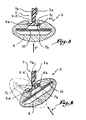
- Figure 1 of label holder is shown in more detail in Figure 2. It essentially comprises a transparent sheath 6 and a body 7 which is mounted on one of the main faces 2 a cardboard folder suspended by any suitable means and , for example, by means of two rivets 8 and 9 passing through a main veil 7 a of the body 7.
- This body 7 also includes a tongue 7 b disposed substantially perpendicular to the veil 7 a and connected to the latter by a strip 7 c of material , thinner than the web 7 a and forming a substantially vertical pivot axis XX '.
- the material of the body 7 is chosen so that the strip 7 c has an elasticity such that it allows the pivoting of the tongue 7 b around the axis XX '.
- polypropylene is particularly suitable for this purpose and the strip 7c can be obtained by pinching the web 7 is achieved in this material.
- the lateral ends of the tongue 7 b are able to cooperate with two longitudinal grooves 6 a and 6 b of the transparent sheath 6.
- the sheath 6 is installed on the body 7 by sliding the tongue 7 b in the grooves 6 a and 6 b until the lower end 6 c of the sheath 6 is substantially at the same height as the lower end of the tongue 7 b .
- the sheath 6 is capable of the same pivoting movements around the axis XX 'as the tongue 7 b .
- An identification label 10 is installed in the sheath 6, by insertion in its upper part in a direction F ", and can be read through the front face of the sheath 6 whose thickness E makes it possible to create a magnifying glass effect .
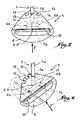
- the sheath 6 and the label 10 can be oriented so that the label is perpendicular to a direction of observation F normal to the bottom of the cabinet 1 or to a direction F 'oblique to this background, and this, by pivoting about the axis XX'.
- the hanging files installed in the right part of the cabinet 1 in FIG. 1 can have a label support in the position of Figure 3 while the hanging files installed in the left part of the cabinet 1 may have a label support in the position of Figure 4. It is understood that, depending on the direction of observation of the support label, the sheath can be pivoted in the opposite direction to reach the position shown in phantom in Figure 4.
- the label support comprises means for immobilizing the sheath in a position oriented relative to its pivot axis. It is indeed important that, when the sheath 6 has been put in place in the position of FIG. 4, it does not automatically return to its position in FIG. 3 under the effect of the elasticity of the strip 7 c .
- the sheath 6 comprises in its upper part an extension 11 provided with three notches 12, 13 and 14 arranged on a part of the extension 11 forming an arc of a circle.
- the veil 7 a comprises, for its part, an end forming a lug 7 d capable of penetrating one of the notches 12 to 14. Referring more particularly to FIGS.
- the lug 7 d is engaged in the central notch 13 when the label must be visible in the direction F, that is to say when the label 10 must be substantially parallel to the bottom of the cabinet 1 in which the suspended file in question is installed. This position is visible in FIG. 5.
- the lug 7 d is engaged in one of the lateral notches, in the example the notch 14.
- a symmetrical position shown in broken lines can be obtained by orienting the sheath 6 in the opposite direction.
- the transition from one position to another is obtained by exerting traction on the sheath 6 so as to release the lug 7 d from the notch 12, 13 or 14 into which it enters.
- This relative movement of the notches relative to the lug 7 d is possible thanks to the elasticity of the materials used for the body 7 and the sheath 6.
- the label support of FIG. 1 comprises second means immobilizing the sheath 6 in a position oriented relative to the axis XX '.
- These second means consist of three notches 22, 23 and 24 formed at the end 6c of the sheath 6, while the body 7 comprises at its lower end a tab 7 e which carries a second lug 7 f .
- Figures 7 and 8 show the position of the lug 7 f respectively in the notch 22 or in the notch 23 depending on the orientation of the label support chosen by the user.
- the user wishes to change the orientation of the sheath 6, he can disengage the lug 7 d from the notch 22 23 or 24 by slightly lifting the sheath 6 and causing the sheath 6 to carry out the desired movement before pushing towards bottom sheath 6 so that a notch covers the lug 7 d .
- the self-weight of the sheath 6 is a factor of stability of the assembly obtained by the cooperation of the lug 7 f and the notch 22, 23 or 24 in which it is engaged.
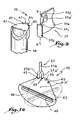
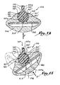
- Figures 9 and 10 show a second embodiment of the invention in which elements similar to those of the embodiment of Figures 1 to 8 bear an identical reference increased by 50.
- the support 55 of this embodiment differs from the previous one essentially in that its body 57 carries in its upper part two pins 57 d and 57 of offset relative to the axis of symmetry of a veil 57 a of the body 57, so that they each simultaneously penetrate into a notch belonging to a series of four notches 62 to 65 formed on the arcuate edge of an extension 61 of a transparent sheath 56.
- This embodiment has the particular advantage that, due to the double immobilization resulting from the two lugs 57 d and 57 d ' , the label support of the invention is very firmly held in the position chosen by the user, for reading a label 60, by rotation of the sheath 56 and a tab e 57 b around a pivot axis XX 'materialized by a band 57 c forming hinge.
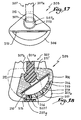
- FIG. 11 shows a third embodiment of the invention in which the elements similar to those of the embodiment of FIGS. 1 to 8 bear identical references increased by 100.
- the support 105 of this embodiment differs from the preceding essentially in that the orientable nature of a sheath 106, in which a label 110 is housed, is obtained thanks to the geometry of the body 107 of this support.
- the body 107 comprises an extension 107b of generally cylindrical shape and provided with grooves or notches 112, 113, 114, 112 ', 113' and 114. These grooves, which are distributed over an arc of a circle formed by the surface of the section of the extension 107 b , extend over the major part of the height of the body 107, that is to say of the support 105.
- the transparent plastic sheath 106 comprises two extensions 111 and 111 'each carrying a lug 117, respectively 117 '.
- Each of the lugs 117 or 117 ' is intended to penetrate one of the grooves 112 to 114 and 112' to 114 '.
- the pins 117 and 117 ′ may extend over the major part of the height of the sheath 106 or be present only over a part of the latter.
- the axis of symmetry of the extension 107b coincides with the pivot axis XX 'of the sheath 106.
- the operation is as follows: When it is necessary to set up the sheath 106 on the body 107, the latter is driven in a vertical translational movement so that the pins 117 and 117 'penetrate into two notches or diametrically opposite grooves.
- the user wishes to orient the sheath 106 relative to the axis XX 'passing through the center of the extension 107 b , he exerts a torque with respect to this axis on the sheath 106 whose extensions 111 and 111' are deformed because of the elastic properties of the material used for its manufacture, which makes it possible to disengage the pins 117 and 117 ′ from the grooves in which they are engaged.
- the pins 117 and 117 'in a second set of grooves or notches When the angular position corresponding to the engagement of the pins 117 and 117 'in a second set of grooves or notches is reached, the pins penetrate into the corresponding grooves under the effect of the elasticity of the extensions 111 and 111 '.
- the device of the invention can thus easily be brought from the position shown in FIG. 12 to one of the positions shown in solid lines or in broken lines in FIG. 13.
- one end 118 ′ of the extension 111 ′ abuts against the web 107 a of the body 107 when the sheath 106 is in an oblique position relative to the main faces of the hanging file on which the support of the invention is mounted.
- This end stop 118 ′ which can be produced over most of the height of the support 105, gives good mechanical stability to the device and avoids deterioration of the latter in the case where a user exercises on the sheath 106 a torque which would tend to make it exceed the position shown in solid lines in FIG. 13.
- the end 118 of the extension 111 also constitutes a stop in the position represented in dashed lines in FIG. 13.
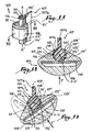
- Figures 14 and 15 show a fourth embodiment of the invention, the constituent elements similar to those of the embodiment of Figures 1 to 8 bear identical references increased by 150.
- the support 155 of this embodiment differs from the previous one essentially in that lugs 167 and 167 'carried by extensions 161 and 161' of a transparent sheath 156 are arranged at the ends of the extensions 161 and 161 'furthest from a label 160. This extreme position of the lugs 167 and 167 'makes it possible to take full advantage of the elastic properties of the plastic material of the extensions 161 and 161' when the sheath 156 is moved from one position to the other.
- the sheath 156 when the sheath 156 is in an oblique position as shown in FIG. 15, one of the lugs 167 or 167 ′ is in abutment against the web 157 a of the body 157 and therefore fills the depending on the end 118 or 118 ′ of the previous embodiment.
- This embodiment therefore constitutes a simplification compared to the previous one while the advantages are retained.
- the grooves or notches 162 to 164 and 162 'to 164' may or may not extend over the major part of the height of the support 155, just as the pins 167 and 167 'can extend over all this height or on a part of it or be made up of several aligned elements capable of penetrating simultaneously into a groove.
- each extension 161 and 161 ' comprises several lugs, for example two, capable of simultaneously penetrating two different grooves in the manner of the embodiment of Figures 9 and 10.
- the translucent sheath carries a single lug on an extension while the extension of the body carries a single series of grooves, the second extension having an internal cylindrical shape capable of cooperating with a cylindrical external shape of the extension of the body.
- Figures 16 to 18 show a fifth embodiment of the invention in which elements similar to those of the embodiment of Figures 1 to 8 bear an identical reference increased by 200.
- the support 205 of this embodiment comprises a body 207 mounted on one side 202a of a file suspended by means of two rivets 208 and 209.
- a transparent sheath 6 is capable of receiving a label 210 by insertion in a direction F "'.
- the body 207 essentially consists of a veil 207 a resting against the face 202 a , a cylindrical rod 207 b extending substantially parallel to the edge of the face 202 a and a tab 207 e extending perpendicularly to the stem 207 b , in the lower part of the body 207.
- the cylindrical rod 207 b On the major part of its height, the cylindrical rod 207 b is connected to the web 207 a .
- the rod 207 b has an end 207 c disengaged from the web 207 a .
- the transparent sheath 206 is made of plastic material and comprises two extensions 211 and 211 ′ capable of enclosing the cylindrical rod 207 b . To do this, the opposite parts of the extensions 211 and 211 ′ each carry a groove in an arc of a circle whose radius is substantially equal to that of the rod 207 b . In its upper part, the sheath 206 carries an extension 212 pierced with a cylindrical orifice 213.
- the body 207 comprises, at its upper part, a finger 207 h extending, from the veil 207 a , in the direction of the end 207 c of rod 207 b .
- the operation is as follows: when it is necessary to put the sheath 206 on the body 207, the latter is driven in a downward vertical translation movement along the axis XX 'of the rod 207 b up to 'at that its lower end 206 c abuts against the tab 207 e .
- the extension 212 is inserted by force between the finger 207 h and the end 207 c .
- the orifice 213 then covers the end 207 c of the rod 207 b .
- the sheath 206 can pivot around the axis XX' to reach the orientation desired by the user while the finger 207 h allows s' oppose the extraction of the sheath 206 upwards in FIG. 16.
- the tab 207 e carries, on an extension 207 q , a lug 207 f oriented towards the rod 207 b , that is to say towards the sheath 206 when the latter is in place on the support.
- the sheath 206 is provided, on its external face, near its lower end 206 c , with a groove 214 into which the lug 207 f penetrates when the sheath is in place.
- the lug 207 f also opposes a possible upward movement of the sheath 206 when it is in place.
- the immobilization of the sheath 206 is carried out only by the finger 207 h or by the lug 207 g .
- the notches 215 to 219 are provided in an arc at the bottom of the groove 214 so that the lug 207 f is able to penetrate into one of them as a function of the position of the sheath 206 around the axis XX 'and immobilize the sheath in this position.
- the notches 215 to 219 may or may not open out into the internal space of the sheath 206 where the label 210 is housed.
- the supports shown in the appended figures include three, four, five or six notches, but the invention is applicable regardless of the number of these notches.
- This number and the position of the notches are determined as a function of the orientation or orientations sought for the sheath. In particular, several oblique positions with angles of 20, 35 and 50 ° can be obtained by a judicious choice, within the reach of those skilled in the art, the number and the position of the notches and / or lugs.
Landscapes
- Details Of Rigid Or Semi-Rigid Containers (AREA)
- Purses, Travelling Bags, Baskets, Or Suitcases (AREA)
- Mirrors, Picture Frames, Photograph Stands, And Related Fastening Devices (AREA)
- Toys (AREA)
- Packaging For Recording Disks (AREA)
Applications Claiming Priority (2)
| Application Number | Priority Date | Filing Date | Title |
|---|---|---|---|
| FR9605520 | 1996-04-26 | ||
| FR9605520A FR2747963B1 (fr) | 1996-04-26 | 1996-04-26 | Support d'etiquette d'identification et dossier suspendu comprenant un tel support |
Publications (2)
| Publication Number | Publication Date |
|---|---|
| EP0803380A1 true EP0803380A1 (de) | 1997-10-29 |
| EP0803380B1 EP0803380B1 (de) | 1999-10-13 |
Family
ID=9491784
Family Applications (1)
| Application Number | Title | Priority Date | Filing Date |
|---|---|---|---|
| EP97420068A Expired - Lifetime EP0803380B1 (de) | 1996-04-26 | 1997-04-24 | Identifizierungsetikettenhalter und Hängeordner mit einem solchen Halter |
Country Status (7)
| Country | Link |
|---|---|
| US (1) | US5890307A (de) |
| EP (1) | EP0803380B1 (de) |
| AU (1) | AU713709B2 (de) |
| DE (1) | DE69700612T2 (de) |
| DK (1) | DK0803380T3 (de) |
| ES (1) | ES2137766T3 (de) |
| FR (1) | FR2747963B1 (de) |
Families Citing this family (5)
| Publication number | Priority date | Publication date | Assignee | Title |
|---|---|---|---|---|
| US20050199685A1 (en) * | 2001-10-22 | 2005-09-15 | Canadian Environmental Office Products Inc. | Suspended file folder |
| US7610707B1 (en) | 2004-06-21 | 2009-11-03 | Payne Edward A | Combined file flagging devices and label holders |
| FR2919823B1 (fr) * | 2007-08-10 | 2010-03-19 | Oblique L | Support d'etiquette pour dossier suspendu et dossier suspendu equipe d'un tel support d'etiquette |
| US7966758B2 (en) * | 2008-06-16 | 2011-06-28 | Susan Scott Watts | Positionable file tab |
| DE102008062947A1 (de) | 2008-12-23 | 2010-06-24 | Esselte Leitz Gmbh & Co. Kg | Kennzeichnungsreiter |
Citations (3)
| Publication number | Priority date | Publication date | Assignee | Title |
|---|---|---|---|---|
| FR1349479A (fr) * | 1962-12-14 | 1964-01-17 | Pupitre de lecture pour dossiers suspendus ou autre à visibilité totale | |
| FR2254952A5 (en) * | 1973-12-13 | 1975-07-11 | Classement Ste Lyonnaise | Carrier bar for suspension filing system - has transparent label cover and reinforcing rod snapping onto hooked strip |
| US4232461A (en) * | 1979-03-19 | 1980-11-11 | Crawford Larry B | Phonograph record album index tabs |
Family Cites Families (11)
| Publication number | Priority date | Publication date | Assignee | Title |
|---|---|---|---|---|
| US1329569A (en) * | 1917-03-26 | 1920-02-03 | Acme Card System Co | Guide-card |
| US2151359A (en) * | 1936-05-12 | 1939-03-21 | Globe Wernicke Co | Tab insert |
| US2248355A (en) * | 1940-10-17 | 1941-07-08 | Charles L Barkley | Angular tab guide |
| US2357070A (en) * | 1943-07-03 | 1944-08-29 | Diebold Inc | File folder and index tab construction |
| US2480686A (en) * | 1944-08-14 | 1949-08-30 | G J Aigner Company | Index strip holder |
| US2545014A (en) * | 1947-04-17 | 1951-03-13 | Remington Rand Inc | Magnifying index tab |
| US2675636A (en) * | 1950-05-20 | 1954-04-20 | Whitney K Munson | Indexing device |
| US3062217A (en) * | 1961-10-09 | 1962-11-06 | Jr William T Woodhouse | Index tab holder |
| US3164917A (en) * | 1962-05-03 | 1965-01-12 | Ralph C Harper | Index tab |
| US3248814A (en) * | 1963-10-16 | 1966-05-03 | Zwolinski Edward | Index tabs |
| US3626619A (en) * | 1968-01-31 | 1971-12-14 | Harold W Boedeker | Guide tab |
-
1996
- 1996-04-26 FR FR9605520A patent/FR2747963B1/fr not_active Expired - Fee Related
-
1997
- 1997-04-24 DE DE69700612T patent/DE69700612T2/de not_active Expired - Fee Related
- 1997-04-24 US US08/842,401 patent/US5890307A/en not_active Expired - Fee Related
- 1997-04-24 ES ES97420068T patent/ES2137766T3/es not_active Expired - Lifetime
- 1997-04-24 DK DK97420068T patent/DK0803380T3/da active
- 1997-04-24 EP EP97420068A patent/EP0803380B1/de not_active Expired - Lifetime
- 1997-04-28 AU AU19137/97A patent/AU713709B2/en not_active Ceased
Patent Citations (3)
| Publication number | Priority date | Publication date | Assignee | Title |
|---|---|---|---|---|
| FR1349479A (fr) * | 1962-12-14 | 1964-01-17 | Pupitre de lecture pour dossiers suspendus ou autre à visibilité totale | |
| FR2254952A5 (en) * | 1973-12-13 | 1975-07-11 | Classement Ste Lyonnaise | Carrier bar for suspension filing system - has transparent label cover and reinforcing rod snapping onto hooked strip |
| US4232461A (en) * | 1979-03-19 | 1980-11-11 | Crawford Larry B | Phonograph record album index tabs |
Also Published As
| Publication number | Publication date |
|---|---|
| DK0803380T3 (da) | 2000-04-25 |
| DE69700612D1 (de) | 1999-11-18 |
| AU1913797A (en) | 1997-10-30 |
| FR2747963B1 (fr) | 1998-06-12 |
| HK1001389A1 (en) | 1998-06-19 |
| US5890307A (en) | 1999-04-06 |
| ES2137766T3 (es) | 1999-12-16 |
| FR2747963A1 (fr) | 1997-10-31 |
| AU713709B2 (en) | 1999-12-09 |
| DE69700612T2 (de) | 2000-05-04 |
| EP0803380B1 (de) | 1999-10-13 |
Similar Documents
| Publication | Publication Date | Title |
|---|---|---|
| BE1005811A5 (fr) | Boitier pour disques compacts ou similaires. | |
| EP2816926B1 (de) | Schutzhülle für mindestens zwei kreditkarten oder dergleichen | |
| EP0206859B1 (de) | Scharnier zum Verbinden von gelenkig miteinander verbundenen Platten oder dgl. | |
| EP3448197B1 (de) | Lager- und ausstellvorrichtung zum lagern und ausstellen einer vielzahl von länglichen handwerkzeugen | |
| WO1997040483A1 (fr) | Dispositif pour maintenir une feuille de papier | |
| EP0362056B1 (de) | Tragbarer Registerkasten | |
| FR2610183A1 (fr) | Chevalet de conference | |
| EP0803380B1 (de) | Identifizierungsetikettenhalter und Hängeordner mit einem solchen Halter | |
| CH620160A5 (de) | ||
| FR2729248A1 (fr) | Boitier pour disque compact notamment | |
| EP1226584A1 (de) | Behälter für cd-platte | |
| EP0273844A1 (de) | Blätterblockhalterung | |
| FR2537320A1 (fr) | Cassette pour disque optique | |
| FR2653929A1 (fr) | Mobile d'actionnement a cle pour interrupteur de securite. | |
| EP1559103A1 (de) | Schutzbehälter für einen plattenförmigen träger numerischer daten | |
| EP3801371B1 (de) | Vorrichtung zur aufbewahrung von orthodontischen zangen | |
| EP0470908B1 (de) | Schauvorrichtung aus Elementen mit in einer Fläche änderungsfähigen, relativen Positionen | |
| WO2008080896A1 (fr) | Dispositif de rangement d'au moins un disque compact | |
| EP1069813B1 (de) | Frontplatte für eine elektronische Baugruppe, elektronische Baugruppe, und deren Einschub- oder Ausziehverfahren aus einem Baugruppenträger | |
| EP0286511B1 (de) | Schreibvorrichtung für ein Registriergerät mit zwei Diagrammscheiben | |
| EP0064927A1 (de) | Gestell für einen mit Bildschirm versehenen Empfänger | |
| BE1003839A5 (fr) | Coffret pour au moins un disque a haute densite d'information. | |
| CH678047A5 (en) | Card dispenser | |
| FR2549971A1 (fr) | Appareil pour visionner des vues par transparence | |
| WO2020012119A1 (fr) | Couteau de type cutter permettant un remplacement securise de la lame |
Legal Events
| Date | Code | Title | Description |
|---|---|---|---|
| PUAI | Public reference made under article 153(3) epc to a published international application that has entered the european phase |
Free format text: ORIGINAL CODE: 0009012 |
|
| AK | Designated contracting states |
Kind code of ref document: A1 Designated state(s): BE CH DE DK ES FR GB IE IT LI NL PT |
|
| 17P | Request for examination filed |
Effective date: 19980110 |
|
| GRAG | Despatch of communication of intention to grant |
Free format text: ORIGINAL CODE: EPIDOS AGRA |
|
| 17Q | First examination report despatched |
Effective date: 19990125 |
|
| GRAG | Despatch of communication of intention to grant |
Free format text: ORIGINAL CODE: EPIDOS AGRA |
|
| GRAH | Despatch of communication of intention to grant a patent |
Free format text: ORIGINAL CODE: EPIDOS IGRA |
|
| GRAH | Despatch of communication of intention to grant a patent |
Free format text: ORIGINAL CODE: EPIDOS IGRA |
|
| RAP1 | Party data changed (applicant data changed or rights of an application transferred) |
Owner name: L'OBLIQUE |
|
| GRAA | (expected) grant |
Free format text: ORIGINAL CODE: 0009210 |
|
| AK | Designated contracting states |
Kind code of ref document: B1 Designated state(s): BE CH DE DK ES FR GB IE IT LI NL PT |
|
| REG | Reference to a national code |
Ref country code: CH Ref legal event code: EP |
|
| REF | Corresponds to: |
Ref document number: 69700612 Country of ref document: DE Date of ref document: 19991118 |
|
| REG | Reference to a national code |
Ref country code: ES Ref legal event code: FG2A Ref document number: 2137766 Country of ref document: ES Kind code of ref document: T3 |
|
| ITF | It: translation for a ep patent filed | ||
| GBT | Gb: translation of ep patent filed (gb section 77(6)(a)/1977) |
Effective date: 19991217 |
|
| REG | Reference to a national code |
Ref country code: IE Ref legal event code: FG4D Free format text: FRENCH |
|
| REG | Reference to a national code |
Ref country code: PT Ref legal event code: SC4A Free format text: AVAILABILITY OF NATIONAL TRANSLATION Effective date: 19991217 |
|
| REG | Reference to a national code |
Ref country code: DK Ref legal event code: T3 |
|
| PLBE | No opposition filed within time limit |
Free format text: ORIGINAL CODE: 0009261 |
|
| STAA | Information on the status of an ep patent application or granted ep patent |
Free format text: STATUS: NO OPPOSITION FILED WITHIN TIME LIMIT |
|
| 26N | No opposition filed | ||
| REG | Reference to a national code |
Ref country code: GB Ref legal event code: IF02 |
|
| PGFP | Annual fee paid to national office [announced via postgrant information from national office to epo] |
Ref country code: DK Payment date: 20030317 Year of fee payment: 7 |
|
| PGFP | Annual fee paid to national office [announced via postgrant information from national office to epo] |
Ref country code: DE Payment date: 20030723 Year of fee payment: 7 |
|
| PG25 | Lapsed in a contracting state [announced via postgrant information from national office to epo] |
Ref country code: DK Free format text: LAPSE BECAUSE OF NON-PAYMENT OF DUE FEES Effective date: 20040430 |
|
| PG25 | Lapsed in a contracting state [announced via postgrant information from national office to epo] |
Ref country code: DE Free format text: LAPSE BECAUSE OF NON-PAYMENT OF DUE FEES Effective date: 20041103 |
|
| PGFP | Annual fee paid to national office [announced via postgrant information from national office to epo] |
Ref country code: IE Payment date: 20050318 Year of fee payment: 9 |
|
| PGFP | Annual fee paid to national office [announced via postgrant information from national office to epo] |
Ref country code: CH Payment date: 20050412 Year of fee payment: 9 |
|
| PGFP | Annual fee paid to national office [announced via postgrant information from national office to epo] |
Ref country code: ES Payment date: 20050414 Year of fee payment: 9 |
|
| PGFP | Annual fee paid to national office [announced via postgrant information from national office to epo] |
Ref country code: PT Payment date: 20050419 Year of fee payment: 9 |
|
| PG25 | Lapsed in a contracting state [announced via postgrant information from national office to epo] |
Ref country code: IE Free format text: LAPSE BECAUSE OF NON-PAYMENT OF DUE FEES Effective date: 20060424 |
|
| PG25 | Lapsed in a contracting state [announced via postgrant information from national office to epo] |
Ref country code: ES Free format text: LAPSE BECAUSE OF NON-PAYMENT OF DUE FEES Effective date: 20060425 |
|
| PG25 | Lapsed in a contracting state [announced via postgrant information from national office to epo] |
Ref country code: LI Free format text: LAPSE BECAUSE OF NON-PAYMENT OF DUE FEES Effective date: 20060430 Ref country code: CH Free format text: LAPSE BECAUSE OF NON-PAYMENT OF DUE FEES Effective date: 20060430 |
|
| PG25 | Lapsed in a contracting state [announced via postgrant information from national office to epo] |
Ref country code: PT Free format text: LAPSE BECAUSE OF NON-PAYMENT OF DUE FEES Effective date: 20061024 |
|
| REG | Reference to a national code |
Ref country code: CH Ref legal event code: PL |
|
| REG | Reference to a national code |
Ref country code: PT Ref legal event code: MM4A Free format text: LAPSE DUE TO NON-PAYMENT OF FEES Effective date: 20061024 |
|
| REG | Reference to a national code |
Ref country code: IE Ref legal event code: MM4A |
|
| REG | Reference to a national code |
Ref country code: ES Ref legal event code: FD2A Effective date: 20060425 |
|
| PGFP | Annual fee paid to national office [announced via postgrant information from national office to epo] |
Ref country code: GB Payment date: 20130521 Year of fee payment: 17 |
|
| PGFP | Annual fee paid to national office [announced via postgrant information from national office to epo] |
Ref country code: IT Payment date: 20130429 Year of fee payment: 17 Ref country code: BE Payment date: 20130530 Year of fee payment: 17 Ref country code: FR Payment date: 20130604 Year of fee payment: 17 Ref country code: NL Payment date: 20130419 Year of fee payment: 17 |
|
| REG | Reference to a national code |
Ref country code: NL Ref legal event code: V1 Effective date: 20141101 |
|
| GBPC | Gb: european patent ceased through non-payment of renewal fee |
Effective date: 20140424 |
|
| REG | Reference to a national code |
Ref country code: FR Ref legal event code: ST Effective date: 20141231 |
|
| PG25 | Lapsed in a contracting state [announced via postgrant information from national office to epo] |
Ref country code: GB Free format text: LAPSE BECAUSE OF NON-PAYMENT OF DUE FEES Effective date: 20140424 |
|
| PG25 | Lapsed in a contracting state [announced via postgrant information from national office to epo] |
Ref country code: NL Free format text: LAPSE BECAUSE OF NON-PAYMENT OF DUE FEES Effective date: 20141101 Ref country code: FR Free format text: LAPSE BECAUSE OF NON-PAYMENT OF DUE FEES Effective date: 20140430 |
|
| PG25 | Lapsed in a contracting state [announced via postgrant information from national office to epo] |
Ref country code: IT Free format text: LAPSE BECAUSE OF NON-PAYMENT OF DUE FEES Effective date: 20140424 |
|
| PG25 | Lapsed in a contracting state [announced via postgrant information from national office to epo] |
Ref country code: BE Free format text: LAPSE BECAUSE OF NON-PAYMENT OF DUE FEES Effective date: 20140430 |