EP0803301A1 - Verfahren zur Herstellung eines Gegenstandes durch superplastische Formung und Diffusionsschweissung - Google Patents
Verfahren zur Herstellung eines Gegenstandes durch superplastische Formung und Diffusionsschweissung Download PDFInfo
- Publication number
- EP0803301A1 EP0803301A1 EP97400905A EP97400905A EP0803301A1 EP 0803301 A1 EP0803301 A1 EP 0803301A1 EP 97400905 A EP97400905 A EP 97400905A EP 97400905 A EP97400905 A EP 97400905A EP 0803301 A1 EP0803301 A1 EP 0803301A1
- Authority
- EP
- European Patent Office
- Prior art keywords
- sheets
- molds
- stack
- expandable frame
- welding
- Prior art date
- Legal status (The legal status is an assumption and is not a legal conclusion. Google has not performed a legal analysis and makes no representation as to the accuracy of the status listed.)
- Granted
Links
- 238000009792 diffusion process Methods 0.000 title claims abstract description 38
- 238000004519 manufacturing process Methods 0.000 title claims abstract description 26
- 230000002093 peripheral effect Effects 0.000 claims abstract description 61
- 238000000034 method Methods 0.000 claims abstract description 44
- 238000003825 pressing Methods 0.000 claims abstract description 10
- 238000003466 welding Methods 0.000 claims description 62
- 230000004888 barrier function Effects 0.000 claims description 12
- 238000002347 injection Methods 0.000 claims description 6
- 239000007924 injection Substances 0.000 claims description 6
- 238000009966 trimming Methods 0.000 claims description 4
- 239000011159 matrix material Substances 0.000 claims description 2
- 229910052751 metal Inorganic materials 0.000 abstract description 6
- 239000002184 metal Substances 0.000 abstract description 6
- 239000007787 solid Substances 0.000 abstract 2
- 238000010438 heat treatment Methods 0.000 description 10
- 238000005520 cutting process Methods 0.000 description 6
- 230000000694 effects Effects 0.000 description 5
- 239000000463 material Substances 0.000 description 3
- 230000008569 process Effects 0.000 description 3
- 230000009471 action Effects 0.000 description 2
- 230000009467 reduction Effects 0.000 description 2
- 229910001069 Ti alloy Inorganic materials 0.000 description 1
- RTAQQCXQSZGOHL-UHFFFAOYSA-N Titanium Chemical compound [Ti] RTAQQCXQSZGOHL-UHFFFAOYSA-N 0.000 description 1
- 229910045601 alloy Inorganic materials 0.000 description 1
- 239000000956 alloy Substances 0.000 description 1
- 230000008901 benefit Effects 0.000 description 1
- 230000000295 complement effect Effects 0.000 description 1
- 230000001186 cumulative effect Effects 0.000 description 1
- 230000008034 disappearance Effects 0.000 description 1
- 238000006073 displacement reaction Methods 0.000 description 1
- 230000000977 initiatory effect Effects 0.000 description 1
- 230000004044 response Effects 0.000 description 1
- 239000000243 solution Substances 0.000 description 1
- 230000007480 spreading Effects 0.000 description 1
- 238000003892 spreading Methods 0.000 description 1
- 239000003351 stiffener Substances 0.000 description 1
- 239000010936 titanium Substances 0.000 description 1
- 229910052719 titanium Inorganic materials 0.000 description 1
- 238000005493 welding type Methods 0.000 description 1
Images


Classifications
-
- B—PERFORMING OPERATIONS; TRANSPORTING
- B21—MECHANICAL METAL-WORKING WITHOUT ESSENTIALLY REMOVING MATERIAL; PUNCHING METAL
- B21D—WORKING OR PROCESSING OF SHEET METAL OR METAL TUBES, RODS OR PROFILES WITHOUT ESSENTIALLY REMOVING MATERIAL; PUNCHING METAL
- B21D26/00—Shaping without cutting otherwise than using rigid devices or tools or yieldable or resilient pads, i.e. applying fluid pressure or magnetic forces
- B21D26/02—Shaping without cutting otherwise than using rigid devices or tools or yieldable or resilient pads, i.e. applying fluid pressure or magnetic forces by applying fluid pressure
- B21D26/053—Shaping without cutting otherwise than using rigid devices or tools or yieldable or resilient pads, i.e. applying fluid pressure or magnetic forces by applying fluid pressure characterised by the material of the blanks
- B21D26/055—Blanks having super-plastic properties
-
- B—PERFORMING OPERATIONS; TRANSPORTING
- B23—MACHINE TOOLS; METAL-WORKING NOT OTHERWISE PROVIDED FOR
- B23K—SOLDERING OR UNSOLDERING; WELDING; CLADDING OR PLATING BY SOLDERING OR WELDING; CUTTING BY APPLYING HEAT LOCALLY, e.g. FLAME CUTTING; WORKING BY LASER BEAM
- B23K20/00—Non-electric welding by applying impact or other pressure, with or without the application of heat, e.g. cladding or plating
- B23K20/02—Non-electric welding by applying impact or other pressure, with or without the application of heat, e.g. cladding or plating by means of a press ; Diffusion bonding
- B23K20/023—Thermo-compression bonding
-
- B—PERFORMING OPERATIONS; TRANSPORTING
- B23—MACHINE TOOLS; METAL-WORKING NOT OTHERWISE PROVIDED FOR
- B23K—SOLDERING OR UNSOLDERING; WELDING; CLADDING OR PLATING BY SOLDERING OR WELDING; CUTTING BY APPLYING HEAT LOCALLY, e.g. FLAME CUTTING; WORKING BY LASER BEAM
- B23K20/00—Non-electric welding by applying impact or other pressure, with or without the application of heat, e.g. cladding or plating
- B23K20/18—Zonal welding by interposing weld-preventing substances between zones not to be welded
Definitions
- the invention mainly relates to a method of manufacturing a single piece from a stack of sheets made of a metal such as a titanium alloy making it possible to implement the techniques of superplastic forming and diffusion welding, commonly called SPF-DB techniques (from English “Superplastic Forming and Diffusion Bonding").
- the invention also relates to a tool making it possible to implement this method.
- the method and the tooling according to the invention can be used in all fields of application of the SPF-DB techniques. Among these fields, the aerospace industry will be mentioned in particular.
- SPF-DB techniques use the properties of certain materials, such as titanium and its alloys, to be able to be permanently and significantly elongated without risk of breakage, when pressure is applied to a sheet of this material, at high temperature. (about 930 ° C). This technique also uses the ability of the same materials to weld by diffusion under the same conditions of temperature and pressure.
- the SPF-DB technique consists of placing a stack between two half-molds of sheets in which care has been taken to insert welding barriers between the regions of the sheets which must not be welded. After closing the mold, at least one diffusion welding operation and at least one superplastic forming operation are generally carried out. The order and number of these operations depends essentially on the geometric characteristics of the parts to be manufactured.
- Diffusion welding operations consist of heating the sheets and applying pressure thereon ensuring their welding in regions not protected by a welding barrier.
- the welding pressure is applied either by injecting a gas under pressure between the stack of sheets and one of the half-molds, or by injecting a gas under pressure between some of the sheets, depending on the type of welding that we want to achieve.
- the superplastic forming operations are carried out by heating the sheets and applying a forming pressure to them. To this end, a pressurized gas is injected between the sheets of the stack. This gas injection has the effect of pressing the sheets against the walls of the two half-molds, except in the regions previously welded by diffusion, so as to form cells.
- the heating of the sheets is carried out either by using a mold fitted with heating means such as heating resistors, or by placing the mold in a heating appliance such as an oven.
- Document US-A-4,426,032 also describes a manufacturing process using SPF-DB techniques. This process differs in particular from that which is described in document US-A-5,055,143 by the fact that the two half-molds are not pressed one against the other but simply linked to each other by bolts defining between them a maximum spacing, and by the fact that a deformable pressure plate is interposed between one of the half-molds and a stack of two sheets intended to form the part.
- the peripheral seal is ensured by an inflatable seal formed in a peripheral region of the stack of sheets intended to be cut during the final trimming of the part. This inflatable seal is produced by welding the two sheets of the stack according to two continuous peripheral weld lines, spaced from each other.
- diffusion welding of the plates of the stack is obtained by introducing a pressurized gas between the pressure plate and the adjacent half-mold, so as to press the sheets of the stack between the pressure plate and the other half-mold.
- the final thickness of the part therefore depends, as in document US-A-5,055,143, on the creep of the metal which occurs during the diffusion welding operation.
- document US-A-4 087 037 proposes a method and a tool for manufacturing parts according to SPF-DB techniques, in which the forming operations are carried out before the diffusion welding operations, which makes it possible to eliminate the welding barriers usually placed in the stack of sheets.
- a deformable pressure plate is interposed between the stack of sheets and one of the half-molds and these are held against each other by means of pliers.
- the application of diffusion welding pressure is ensured by means of a first inflatable bladder which is interposed between the pressure plate and the adjacent half-mold.
- a second inflatable bladder, of annular shape can be interposed between a peripheral region of the stack of sheets and the half-mold adjacent to the first bladder.
- the subject of the invention is a method and a tool making it possible to manufacture a single piece by SPF-DB techniques, in such a way that the thickness of the piece obtained is controlled with great precision, both when the piece is relatively flat only when it has a significant curvature or curve.
- a method of manufacturing a single piece is proposed, using superplastic forming and diffusion welding techniques, according to which a stack of sheets is placed between two half-molds, pressure is applied to these two. half-molds, so as to pinch a peripheral region of the stack between them until the two half-molds come into mechanical abutment, and at least one pressure is applied by injecting gas between the two half-molds welding and forming, to get said one-piece piece, characterized by the fact that an expandable frame is placed between the peripheral region of the sheet stack and one of the half-molds, this frame is clamped with this peripheral region between the two half-molds, then the expandable frame is inflated while maintaining the half-molds in mechanical abutment, so as to weld the sheets by diffusion along the peripheral region of the stack, before applying the welding and forming pressure.
- an expandable frame is used formed of two superimposed sheets previously welded along internal and external peripheral weld lines and a welding barrier is interposed between the frame and the stack.
- the sheets of the stack and the sheets of the expandable frame are then welded simultaneously along the outer peripheral weld line.
- the two half-molds are separated, then the part obtained and the sheets of the expandable frame are cut simultaneously inside the outer peripheral weld line, so as to separate the expandable frame of the part obtained and to simultaneously carry out a final trimming of the latter.
- two half-molds are used which respectively have a punch shape and a die shape.
- the invention also relates to a tool for manufacturing a single piece, using techniques forming and diffusion welding, comprising two half-molds equipped with mechanical abutment surfaces capable of coming into abutment against one another, means for pressing the two half-molds against one another until the coming to bear mechanical stops, and gas injection means between the two half-molds, capable of applying at least one welding and forming pressure on the sheets of a stack of sheets placed between the two half-molds , to obtain a single piece, characterized in that it further comprises an expandable frame, capable of being placed between a peripheral region of the stack of sheets and one of the half-molds, and means for inflating this expandable frame.
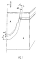
- FIGS. 1 to 4 the various stages of the manufacture of a hollow one-piece part are shown, constituted by a panel of substantially flat geometry, reinforced internally by stiffeners.
- This geometry constitutes only an example intended to illustrate in a simple way the method according to the invention.
- a tool which comprises a mold 10 formed by two half-molds 12 and 14, the facing surfaces 16 and 18 of which define an imprint complementary to the external shape of the part to be manufactured, when the two half-molds 12 and 14 are joined. More precisely, each of the half-molds 12 and 14 has a projecting peripheral rim terminated by a plane mechanical abutment surface 20, 22. These abutment surfaces 20 and 22 are arranged so that they can come to bear one against the other, as shown in Figures 2 and 3, to give the formed impression between the surfaces 16 and 18 a precise well-defined thickness.
- Pressure application means are associated with the mold 10 so as to allow a predetermined pressure to be applied to the two half-molds, until they come to bear. abutment surfaces 20 and 22 against each other.
- These pressure application means may in particular be constituted by a press or by any equivalent device capable of applying an appropriate pressure to the external faces of the half-molds 12 and 14 opposite their surfaces 16 and 18.
- the tool also includes heating means, not illustrated in the figure.
- These heating means can in particular be constituted by electrical resistances embedded in the half-molds 12 and 14 or by an oven or an equivalent device, in which the mold 10 is placed. They make it possible to raise the temperature inside this mold up to a value (for example, around 930 ° C.) compatible with the use of the SPF-DB technique.
- the thickness of the space delimited between these planar surfaces 17 and 19 is slightly less than the cumulative thickness of a stack of sheets 26 and a frame expandable 28 capable of being placed in this space.
- the stack of sheets 26 is intended to form the single piece that it is desired to manufacture.
- Welding barriers (not shown) are interposed between the different sheets 26 of the stack, at the locations for which welding of the sheets is not desired.
- the stack is formed of three sheets 26. A different number of sheets 26 can of course be used depending on the characteristics of the part that it is desired to produce.
- the expandable frame 28 is formed of two superposed sheets 30, previously welded together along a line 32 of continuous inner peripheral weld and along a line 34 of continuous outer peripheral weld.
- the line 34 of continuous external peripheral weld extends in the thickness of the stack of sheets 26, so as to ensure an initial relative positioning of the expandable frame 28 relative to the stack of sheets 26 as well as a relative initial positioning of the sheets of this stack.
- the continuous weld lines 32 and 34 define between the two sheets 30 of the expandable frame 28 an enclosed space 35 into which a pressurized gas can be injected through a passage 36 ( Figure 2). This gas injection inflates the expandable frame 28, as will be explained later.
- This welding barrier 38 has the function of preventing the welding of the adjacent sheets of the stack of sheets 26 and of the expandable frame 28 during inflation of the latter.
- a welding barrier can also be placed between the sheets 30 of the expandable frame 28, in the enclosed space 35.
- the expandable frame 28 constitutes one of the elements of the tool according to the invention.
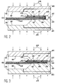
- the tool according to the invention further comprises and in a known manner passages as illustrated at 40 and 42 in FIG. 3, making it possible to inject a gas under pressure in the appropriate regions inside the mold 10, so as to ensure the application of welding pressures by diffusion and superplastic forming.
- the arrangement of these passages 40 and 42 essentially depends on the geometry of the part that one wishes to produce. This arrangement, the development of which is familiar to users of SPF-DB techniques, is not part of the invention.
- the operator cuts the sheets 26 from which the one-piece piece is to be manufactured, so that the dimensions of these sheets slightly exceed the final dimensions of the piece.
- the operator also cuts the sheets 30 intended to form the expandable frame 28. Generally, this cutting is carried out so that the outer contour of the expandable frame 28 is substantially identical to the outer contour of the sheets 26. As will be explained later, the outer contour of the sheets 30 forming the expandable frame 28 may however have more complex shapes when the contour of the workpiece has recessed parts. Likewise, the inner contour of the sheets 30 intended to form the expandable frame 28 is cut so that these sheets 30 have a generally uniform width. In some cases, the inner contour of the sheets 30 may however have protruding parts, as will also be explained below.
- the inner 32 and outer 34 weld lines are made, after taking care to interpose the welding barrier 38 between the adjacent sheets 26 and 30 and appropriate welding barriers (not shown) between the sheets 26.
- the expandable frame 28 is formed and it constitutes, with the stack of sheets 26, a unitary assembly which can be placed between the two half-molds 12 and 14 after their opening.
- the peripheral region of the stack of sheets 26 as well as the expandable frame 28 are then placed between the surfaces 17 and 19 of the two half-molds 12 and 14. Under these conditions, the abutment surfaces 20 and 22 formed on these two half -mussels remain spaced from each other by a certain distance ( Figure 1).
- the heating means (not shown) are then used to raise the temperature in the mold 10 to the value necessary for forming. superplastic and diffusion welding.
- this temperature for example, approximately 930 ° C.
- a pressure sufficient to ensure diffusion welding is applied to the two half-molds 12 and 14, using the pressure means symbolized by the arrows 24. peripheral regions of the plates 26 which are then pinched between the surfaces 17 and 19 of the two half-molds.
- the temperature and pressure applied to the peripheral region of the stack of sheets 26 as well as to the expandable frame 28 have the effect of initiating the diffusion welding of the sheets 26 in this peripheral region. This results in a creep of the metal outwards and a reduction in the thickness of the sheets 26 in this peripheral region. This phenomenon continues until the abutment surfaces 20 and 22 come to bear, illustrated in FIG. 2.
- the expandable frame 28 is inflated by injection of a gas under pressure through the passage 36.
- the start of inflation can be controlled either in response to the signal delivered by a sensor detecting the contact between the surfaces 20 and 22, or by a time delay system implemented as soon as the pressure is applied to the half-molds 12 and 14.
- the inflation of the expandable frame 28 makes it possible to continue applying the pressure necessary for welding the sheets 26 by diffusion, in their peripheral region, after the abutment surfaces 20 and 22 have come into contact. voluntarily exaggerated in FIG. 2 the effect of this inflation on the sheets 26.
- pressurized gas into the expandable frame 28 continues for a time sufficient to ensure completion of the welding by diffusion of the sheets 26 in their peripheral region.
- first of all the diffusion welding of the different sheets 26 is carried out, in the zones to be welded situated inside the region. peripheral of the stack, by injection of gas under pressure through the passages 40.
- the superplastic forming is then carried out by injecting between the sheets 26 a gas under pressure through the passage 42.
- FIG. 4 represents the part obtained when these various operations are finished, after opening the mold 10. More precisely, it can be seen in this FIG. 4 that a simultaneous cutting of the sheets 26 and 30 along a cutting line 43 located inside of the outer peripheral welding line 34 34 and near this line simultaneously makes it possible to separate the expandable frame 28 from the part 44 and to carry out the final trimming of the latter.
- the expandable frame 28 thus constitutes a disposable tool.
- the superplastic forming of the part has the effect of pressing the outer sheets of the stack of sheets 26 against the surfaces 16 and 18 of the two half-molds 12 and 14 while the latter are in abutment against one another by their abutment surface 20 and 22. Consequently, the thickness of the part 44 obtained can be determined with great precision and perfectly reproducible.
- this advantage is particularly important when the one-piece part which it is desired to manufacture is not a planar or substantially planar panel but a part of curved shape, having a curvature which can be significant. .
- the half-mold 12 is in the form of a punch while the half-mold 14 is in the form of a matrix.
- the two surfaces 17 and 19 of these half-molds, between which the expandable frame 28 and the peripheral region of the stack of sheets 26 are pinched, are then strongly inclined relative to the direction of relative movement of the two half -moulds 12 and 14 under the action of the pressure means symbolized by the arrows 24.
- the abutment surfaces 20 and 22 remain flat surfaces oriented in a direction perpendicular to this direction of relative movement of the two half-molds.
- the tooling and the method according to the invention make it possible, as we have seen previously, to carry out superplastic forming by applying the external sheets of the stack of sheets 26 against surfaces 16 and 18 whose spacing is precisely fixed by the abutment of the abutment surfaces 20 and 22.
- the expandable frame 28 allows, as before, to complete the diffusion welding of the peripheral regions of the sheets 26, despite the disappearance of the pressure applied to these regions peripherals by the two half-molds when the abutment surfaces 20 and 22 come to bear against one another.
- FIGS. 6 and 7 There are shown by way of examples in FIGS. 6 and 7 two monobloc parts 44 capable of being manufactured by the method according to the invention.
- the part illustrated in FIG. 6 is a part having a strong curvature as well as a relatively smooth concave surface 46.
- the convex surface 48 of the part 44 obtained by superplastic forming, is protruding except on its peripheral region.
- the part 44 illustrated in FIG. 7 is a strongly curved part which has a projecting central part both on its convex face 48 and on its concave face 46.
- the rim of the projecting central parts can have a complex shape embodied here by a welding island 50.
- This welding island 50 extends towards the inside of the part the peripheral region in which all the sheets 26 are welded by diffusion.
- Such a shape can be obtained, in accordance with the invention, by giving the facing surfaces 16 and 18 of the two half-molds 12 and 14 the appropriate shapes and by extending inward the two sheets 30 forming the expandable frame 28, in order to produce the welding island 50 during the preliminary operation of welding the sheets in their peripheral region.
- the method according to the invention also makes it possible to manufacture one-piece parts having a tormented external contour, even in the case where the dimensions of a notch such as the notch 52 on FIG. 8 are too large for a diffusion welding of the different sheets 26 to be possible by the simple action of the pressure means 24 acting on the two half-molds 12 and 14.
- a stack of sheets 26 is placed in the mold having an outline without cutout and an expandable frame 28 of reduced and substantially uniform width is superimposed on this stack of sheets, which follows the outline of the part that is wants to manufacture.
- the shapes of the facing surfaces 16 and 18 of the half-molds 12 and 14 are then adapted to the shapes of the outline of the part to be manufactured.
- the expandable frame 28 After coming into abutment of the abutment surfaces 20 and 22 formed on the two half-molds, the expandable frame 28 is inflated according to the method described above. Due to the reduced width of the expandable frame 28, the pressure applied by this frame on the stack of sheets 26 is sufficient in all point to ensure efficient diffusion welding of the different sheets. When this welding is finished and thus delimits the final periphery of the part to be manufactured, the operations of superplastic forming and of diffusion welding are carried out in a conventional manner.
- the cutting of the sheets 26 of the stack and of the sheets 30 of the expandable frame 28 inside the outer peripheral weld line 34 (in broken lines in FIG. 8) and in the immediate vicinity of this line of welding makes it possible to obtain the one-piece part having the desired external profile.
- the cutting line 43 is illustrated in dashed lines in FIG. 8.
- the dimensioning of the part is therefore ensured with great precision and in a perfectly reproducible manner.
- the method and the tool in accordance with the invention can be used for the manufacture of parts of extremely varied dimensions and shapes.
- the number of sheets 26 of the stack initially placed in the mold can be any number greater than or equal to two.
Landscapes
- Engineering & Computer Science (AREA)
- Mechanical Engineering (AREA)
- Physics & Mathematics (AREA)
- Fluid Mechanics (AREA)
- Shaping Metal By Deep-Drawing, Or The Like (AREA)
- Pressure Welding/Diffusion-Bonding (AREA)
- Lining Or Joining Of Plastics Or The Like (AREA)
Applications Claiming Priority (2)
| Application Number | Priority Date | Filing Date | Title |
|---|---|---|---|
| FR9605249A FR2747949B1 (fr) | 1996-04-25 | 1996-04-25 | Procede et outillage de fabrication d'une piece monobloc par les techniques de formage superplastique et de soudage par diffusion |
| FR9605249 | 1996-04-25 |
Publications (2)
| Publication Number | Publication Date |
|---|---|
| EP0803301A1 true EP0803301A1 (de) | 1997-10-29 |
| EP0803301B1 EP0803301B1 (de) | 2001-03-28 |
Family
ID=9491594
Family Applications (1)
| Application Number | Title | Priority Date | Filing Date |
|---|---|---|---|
| EP19970400905 Expired - Lifetime EP0803301B1 (de) | 1996-04-25 | 1997-04-22 | Verfahren zur Herstellung eines Gegenstandes durch superplastische Formung und Diffusionsschweissung |
Country Status (4)
| Country | Link |
|---|---|
| EP (1) | EP0803301B1 (de) |
| DE (1) | DE69704388T2 (de) |
| ES (1) | ES2159381T3 (de) |
| FR (1) | FR2747949B1 (de) |
Cited By (3)
| Publication number | Priority date | Publication date | Assignee | Title |
|---|---|---|---|---|
| CN113333935A (zh) * | 2021-04-30 | 2021-09-03 | 成都飞机工业(集团)有限责任公司 | 一种曲腹板面钛合金超塑成形-扩散连接坯料制备方法 |
| CN114571190A (zh) * | 2022-03-08 | 2022-06-03 | 中国航空制造技术研究院 | 一种spf/db空心结构成形方法 |
| WO2024028552A1 (fr) * | 2022-08-02 | 2024-02-08 | Safran Nacelles | Procédé de fabrication de canalisations pour un échangeur de chaleur |
Families Citing this family (1)
| Publication number | Priority date | Publication date | Assignee | Title |
|---|---|---|---|---|
| CN101912919B (zh) * | 2010-07-16 | 2012-04-25 | 沈阳黎明航空发动机(集团)有限责任公司 | 一种气胀成形和热成形复合成形方法及其采用的装置 |
Citations (3)
| Publication number | Priority date | Publication date | Assignee | Title |
|---|---|---|---|---|
| US4087037A (en) * | 1976-07-09 | 1978-05-02 | Mcdonnell Douglas Corporation | Method of and tools for producing superplastically formed and diffusion bonded structures |
| JPS6297782A (ja) * | 1985-10-23 | 1987-05-07 | Kawasaki Heavy Ind Ltd | 金属板の接合および成形方法 |
| US5055143A (en) * | 1990-03-26 | 1991-10-08 | Mcdonnell Douglas Corporation | Re-entrant angle closure on superplastically formed structure |
-
1996
- 1996-04-25 FR FR9605249A patent/FR2747949B1/fr not_active Expired - Fee Related
-
1997
- 1997-04-22 ES ES97400905T patent/ES2159381T3/es not_active Expired - Lifetime
- 1997-04-22 EP EP19970400905 patent/EP0803301B1/de not_active Expired - Lifetime
- 1997-04-22 DE DE1997604388 patent/DE69704388T2/de not_active Expired - Lifetime
Patent Citations (3)
| Publication number | Priority date | Publication date | Assignee | Title |
|---|---|---|---|---|
| US4087037A (en) * | 1976-07-09 | 1978-05-02 | Mcdonnell Douglas Corporation | Method of and tools for producing superplastically formed and diffusion bonded structures |
| JPS6297782A (ja) * | 1985-10-23 | 1987-05-07 | Kawasaki Heavy Ind Ltd | 金属板の接合および成形方法 |
| US5055143A (en) * | 1990-03-26 | 1991-10-08 | Mcdonnell Douglas Corporation | Re-entrant angle closure on superplastically formed structure |
Non-Patent Citations (1)
| Title |
|---|
| PATENT ABSTRACTS OF JAPAN vol. 011, no. 310 (M - 630) 9 October 1987 (1987-10-09) * |
Cited By (4)
| Publication number | Priority date | Publication date | Assignee | Title |
|---|---|---|---|---|
| CN113333935A (zh) * | 2021-04-30 | 2021-09-03 | 成都飞机工业(集团)有限责任公司 | 一种曲腹板面钛合金超塑成形-扩散连接坯料制备方法 |
| CN114571190A (zh) * | 2022-03-08 | 2022-06-03 | 中国航空制造技术研究院 | 一种spf/db空心结构成形方法 |
| WO2024028552A1 (fr) * | 2022-08-02 | 2024-02-08 | Safran Nacelles | Procédé de fabrication de canalisations pour un échangeur de chaleur |
| FR3138689A1 (fr) * | 2022-08-02 | 2024-02-09 | Safran Nacelles | Procédé de fabrication de canalisations pour un échangeur de chaleur |
Also Published As
| Publication number | Publication date |
|---|---|
| DE69704388T2 (de) | 2001-10-31 |
| FR2747949B1 (fr) | 1998-07-17 |
| ES2159381T3 (es) | 2001-10-01 |
| EP0803301B1 (de) | 2001-03-28 |
| FR2747949A1 (fr) | 1997-10-31 |
| DE69704388D1 (de) | 2001-05-03 |
Similar Documents
| Publication | Publication Date | Title |
|---|---|---|
| EP0015202B1 (de) | Ringförmige Dichtung für das Giessen ophthalmischer oder optischer Linsen aus organischem Material und Verfahren zur Anwendung dieser Dichtung | |
| EP0669183B1 (de) | Schweissverfahren für zwei Teile einer Schaufel | |
| EP0894046B1 (de) | Verfahren zum herstellen eines fertigen bauteiles mit einem bereich der fähig ist ein durchgang zu bilden, fertiges bauteil und entsprechende einheit | |
| FR2806347A1 (fr) | Procede et systeme de moulage d'un materiau sandwich thermoplastique et article embouti ainsi produit | |
| EP3178631B1 (de) | Formvorrichtung zum warmformen durch ansaugen, produktionsverfahren, bei der sie zum einsatz kommt und hergestellter gegenstand | |
| FR2949699A1 (fr) | Procede de fabrication d'un module a zone creuse, de preference pour la circulation de fluide | |
| EP1171272B1 (de) | Formvorrichtung zum polymerisieren von profilierten teilen aus verbundwerkstoff | |
| EP1382436B1 (de) | Verfahren zum Formen eines Verbundwerkstoffgegenstandes und Vorrichtung zur Durchführung dieses Verfahrens | |
| EP2111333B1 (de) | Verfahren zur fixierung erster und zweiter thermoplastischer teile | |
| CA2475024C (fr) | Procede de fabrication de pieces par soudage par diffusion et par formage superplastique, et moule pour mettre en oeuvre un tel procede | |
| EP1190786B1 (de) | Verfahren zum Hochdruckumformen von Blechen und Vorrichtung zur Durchführung des Verfahrens | |
| EP0803301B1 (de) | Verfahren zur Herstellung eines Gegenstandes durch superplastische Formung und Diffusionsschweissung | |
| EP0433203B1 (de) | Verfahren und Vorrichtung zum Tiefziehen von konischen Behältern und nach diesem Verfahren hergestellter Behälter | |
| FR2692504A1 (fr) | Procédé et dispositif de formage à tiède d'un flan de tôle en acier. | |
| EP2955000A1 (de) | Formvorrichtung zum warmformen, und produktionsverfahren, bei der sie zum einsatz kommt, und hergestellter kleidungsteil | |
| WO1999041058A1 (fr) | Procede de pliage de profiles comportant un corps creux et une feuille de revetement et profile plie par ce procede | |
| EP0707533B1 (de) | Verfahren zur herstellung eines mehrschichtigen gegenstandes durch giessen und form zur herstellung eines solchen gegenstandes | |
| EP1125720A1 (de) | Verfahren und Vorrichtiung zur Herstellung eines dekorierten Gegenstandes | |
| FR2754199A1 (fr) | Procede de fabrication, par soudage par diffusion et deformation superplastique, d'une piece comportant une cavite et application a la creation de raidisseurs dans une structure constitutive d'aeronef | |
| EP1095840B1 (de) | Kraftfahrzeuglenkrad und Verfahren zu seiner Herstellung | |
| WO2000050182A1 (fr) | Bague a retreindre, procede de fabrication et installation de fabrication. | |
| WO2026022308A1 (fr) | Procédé de thermocompression pour fabriquer une pièce en matériau composite à matrice polymère thermoplastique | |
| FR2866827A1 (fr) | Procede de placage d'une couche souple sur un element rigide et procede de decoration dudit element rigide | |
| FR2543130A1 (fr) | Procede et matrice pour le bombage d'une plaque de verre mince, et plaque de verre mince ainsi bombee | |
| FR2845309A1 (fr) | Moule de thermoformage, comprenant un dispositif de maintien du flan a thermoformer |
Legal Events
| Date | Code | Title | Description |
|---|---|---|---|
| PUAI | Public reference made under article 153(3) epc to a published international application that has entered the european phase |
Free format text: ORIGINAL CODE: 0009012 |
|
| AK | Designated contracting states |
Kind code of ref document: A1 Designated state(s): BE DE ES GB IT NL |
|
| 17P | Request for examination filed |
Effective date: 19980402 |
|
| GRAG | Despatch of communication of intention to grant |
Free format text: ORIGINAL CODE: EPIDOS AGRA |
|
| 17Q | First examination report despatched |
Effective date: 20000616 |
|
| GRAG | Despatch of communication of intention to grant |
Free format text: ORIGINAL CODE: EPIDOS AGRA |
|
| GRAH | Despatch of communication of intention to grant a patent |
Free format text: ORIGINAL CODE: EPIDOS IGRA |
|
| GRAH | Despatch of communication of intention to grant a patent |
Free format text: ORIGINAL CODE: EPIDOS IGRA |
|
| GRAA | (expected) grant |
Free format text: ORIGINAL CODE: 0009210 |
|
| AK | Designated contracting states |
Kind code of ref document: B1 Designated state(s): BE DE ES GB IT NL |
|
| ITF | It: translation for a ep patent filed | ||
| REF | Corresponds to: |
Ref document number: 69704388 Country of ref document: DE Date of ref document: 20010503 |
|
| GBT | Gb: translation of ep patent filed (gb section 77(6)(a)/1977) |
Effective date: 20010503 |
|
| RAP2 | Party data changed (patent owner data changed or rights of a patent transferred) |
Owner name: AEROSPATIALE MATRA |
|
| RAP2 | Party data changed (patent owner data changed or rights of a patent transferred) |
Owner name: MATRA HAUTES TECHNOLOGIES |
|
| REG | Reference to a national code |
Ref country code: ES Ref legal event code: FG2A Ref document number: 2159381 Country of ref document: ES Kind code of ref document: T3 |
|
| RAP2 | Party data changed (patent owner data changed or rights of a patent transferred) |
Owner name: AEROSPATIALE MATRA TECHNOLOGIES |
|
| RAP2 | Party data changed (patent owner data changed or rights of a patent transferred) |
Owner name: EUROPEAN AERONAUTIC DEFENCE AND SPACE COMPANY - EA |
|
| NLT2 | Nl: modifications (of names), taken from the european patent patent bulletin |
Owner name: AEROSPATIALE MATRA |
|
| NLT2 | Nl: modifications (of names), taken from the european patent patent bulletin |
Owner name: AEROSPATIALE MATRA TECHNOLOGIES;EUROPEAN AERONAUTI |
|
| REG | Reference to a national code |
Ref country code: GB Ref legal event code: IF02 |
|
| PLBE | No opposition filed within time limit |
Free format text: ORIGINAL CODE: 0009261 |
|
| STAA | Information on the status of an ep patent application or granted ep patent |
Free format text: STATUS: NO OPPOSITION FILED WITHIN TIME LIMIT |
|
| 26N | No opposition filed | ||
| REG | Reference to a national code |
Ref country code: ES Ref legal event code: PC2A |
|
| PGFP | Annual fee paid to national office [announced via postgrant information from national office to epo] |
Ref country code: NL Payment date: 20050403 Year of fee payment: 9 |
|
| PG25 | Lapsed in a contracting state [announced via postgrant information from national office to epo] |
Ref country code: NL Free format text: LAPSE BECAUSE OF NON-PAYMENT OF DUE FEES Effective date: 20061101 |
|
| NLV4 | Nl: lapsed or anulled due to non-payment of the annual fee |
Effective date: 20061101 |
|
| PGFP | Annual fee paid to national office [announced via postgrant information from national office to epo] |
Ref country code: ES Payment date: 20100427 Year of fee payment: 14 |
|
| PGFP | Annual fee paid to national office [announced via postgrant information from national office to epo] |
Ref country code: IT Payment date: 20100426 Year of fee payment: 14 Ref country code: DE Payment date: 20100423 Year of fee payment: 14 |
|
| PGFP | Annual fee paid to national office [announced via postgrant information from national office to epo] |
Ref country code: BE Payment date: 20100419 Year of fee payment: 14 |
|
| PGFP | Annual fee paid to national office [announced via postgrant information from national office to epo] |
Ref country code: GB Payment date: 20100420 Year of fee payment: 14 |
|
| BERE | Be: lapsed |
Owner name: EUROPEAN AERONAUTIC DEFENCE AND SPACE CY *EADS FRA Effective date: 20110430 |
|
| REG | Reference to a national code |
Ref country code: DE Ref legal event code: R119 Ref document number: 69704388 Country of ref document: DE |
|
| REG | Reference to a national code |
Ref country code: DE Ref legal event code: R119 Ref document number: 69704388 Country of ref document: DE |
|
| GBPC | Gb: european patent ceased through non-payment of renewal fee |
Effective date: 20110422 |
|
| PG25 | Lapsed in a contracting state [announced via postgrant information from national office to epo] |
Ref country code: BE Free format text: LAPSE BECAUSE OF NON-PAYMENT OF DUE FEES Effective date: 20110430 |
|
| PG25 | Lapsed in a contracting state [announced via postgrant information from national office to epo] |
Ref country code: IT Free format text: LAPSE BECAUSE OF NON-PAYMENT OF DUE FEES Effective date: 20110422 Ref country code: GB Free format text: LAPSE BECAUSE OF NON-PAYMENT OF DUE FEES Effective date: 20110422 |
|
| REG | Reference to a national code |
Ref country code: ES Ref legal event code: FD2A Effective date: 20120604 |
|
| PG25 | Lapsed in a contracting state [announced via postgrant information from national office to epo] |
Ref country code: ES Free format text: LAPSE BECAUSE OF NON-PAYMENT OF DUE FEES Effective date: 20110423 |
|
| PG25 | Lapsed in a contracting state [announced via postgrant information from national office to epo] |
Ref country code: DE Free format text: LAPSE BECAUSE OF NON-PAYMENT OF DUE FEES Effective date: 20111031 |