EP0803301A1 - Method of manufacturing an article by superplastic forming and diffusion bonding - Google Patents
Method of manufacturing an article by superplastic forming and diffusion bonding Download PDFInfo
- Publication number
- EP0803301A1 EP0803301A1 EP97400905A EP97400905A EP0803301A1 EP 0803301 A1 EP0803301 A1 EP 0803301A1 EP 97400905 A EP97400905 A EP 97400905A EP 97400905 A EP97400905 A EP 97400905A EP 0803301 A1 EP0803301 A1 EP 0803301A1
- Authority
- EP
- European Patent Office
- Prior art keywords
- sheets
- molds
- stack
- expandable frame
- welding
- Prior art date
- Legal status (The legal status is an assumption and is not a legal conclusion. Google has not performed a legal analysis and makes no representation as to the accuracy of the status listed.)
- Granted
Links
- 238000009792 diffusion process Methods 0.000 title claims abstract description 38
- 238000004519 manufacturing process Methods 0.000 title claims abstract description 26
- 230000002093 peripheral effect Effects 0.000 claims abstract description 61
- 238000000034 method Methods 0.000 claims abstract description 44
- 238000003825 pressing Methods 0.000 claims abstract description 10
- 238000003466 welding Methods 0.000 claims description 62
- 230000004888 barrier function Effects 0.000 claims description 12
- 238000002347 injection Methods 0.000 claims description 6
- 239000007924 injection Substances 0.000 claims description 6
- 238000009966 trimming Methods 0.000 claims description 4
- 239000011159 matrix material Substances 0.000 claims description 2
- 229910052751 metal Inorganic materials 0.000 abstract description 6
- 239000002184 metal Substances 0.000 abstract description 6
- 239000007787 solid Substances 0.000 abstract 2
- 238000010438 heat treatment Methods 0.000 description 10
- 238000005520 cutting process Methods 0.000 description 6
- 230000000694 effects Effects 0.000 description 5
- 239000000463 material Substances 0.000 description 3
- 230000008569 process Effects 0.000 description 3
- 230000009471 action Effects 0.000 description 2
- 230000009467 reduction Effects 0.000 description 2
- 229910001069 Ti alloy Inorganic materials 0.000 description 1
- RTAQQCXQSZGOHL-UHFFFAOYSA-N Titanium Chemical compound [Ti] RTAQQCXQSZGOHL-UHFFFAOYSA-N 0.000 description 1
- 229910045601 alloy Inorganic materials 0.000 description 1
- 239000000956 alloy Substances 0.000 description 1
- 230000008901 benefit Effects 0.000 description 1
- 230000000295 complement effect Effects 0.000 description 1
- 230000001186 cumulative effect Effects 0.000 description 1
- 230000008034 disappearance Effects 0.000 description 1
- 238000006073 displacement reaction Methods 0.000 description 1
- 230000000977 initiatory effect Effects 0.000 description 1
- 230000004044 response Effects 0.000 description 1
- 239000000243 solution Substances 0.000 description 1
- 230000007480 spreading Effects 0.000 description 1
- 238000003892 spreading Methods 0.000 description 1
- 239000003351 stiffener Substances 0.000 description 1
- 239000010936 titanium Substances 0.000 description 1
- 229910052719 titanium Inorganic materials 0.000 description 1
- 238000005493 welding type Methods 0.000 description 1
Images


Classifications
-
- B—PERFORMING OPERATIONS; TRANSPORTING
- B21—MECHANICAL METAL-WORKING WITHOUT ESSENTIALLY REMOVING MATERIAL; PUNCHING METAL
- B21D—WORKING OR PROCESSING OF SHEET METAL OR METAL TUBES, RODS OR PROFILES WITHOUT ESSENTIALLY REMOVING MATERIAL; PUNCHING METAL
- B21D26/00—Shaping without cutting otherwise than using rigid devices or tools or yieldable or resilient pads, i.e. applying fluid pressure or magnetic forces
- B21D26/02—Shaping without cutting otherwise than using rigid devices or tools or yieldable or resilient pads, i.e. applying fluid pressure or magnetic forces by applying fluid pressure
- B21D26/053—Shaping without cutting otherwise than using rigid devices or tools or yieldable or resilient pads, i.e. applying fluid pressure or magnetic forces by applying fluid pressure characterised by the material of the blanks
- B21D26/055—Blanks having super-plastic properties
-
- B—PERFORMING OPERATIONS; TRANSPORTING
- B23—MACHINE TOOLS; METAL-WORKING NOT OTHERWISE PROVIDED FOR
- B23K—SOLDERING OR UNSOLDERING; WELDING; CLADDING OR PLATING BY SOLDERING OR WELDING; CUTTING BY APPLYING HEAT LOCALLY, e.g. FLAME CUTTING; WORKING BY LASER BEAM
- B23K20/00—Non-electric welding by applying impact or other pressure, with or without the application of heat, e.g. cladding or plating
- B23K20/02—Non-electric welding by applying impact or other pressure, with or without the application of heat, e.g. cladding or plating by means of a press ; Diffusion bonding
- B23K20/023—Thermo-compression bonding
-
- B—PERFORMING OPERATIONS; TRANSPORTING
- B23—MACHINE TOOLS; METAL-WORKING NOT OTHERWISE PROVIDED FOR
- B23K—SOLDERING OR UNSOLDERING; WELDING; CLADDING OR PLATING BY SOLDERING OR WELDING; CUTTING BY APPLYING HEAT LOCALLY, e.g. FLAME CUTTING; WORKING BY LASER BEAM
- B23K20/00—Non-electric welding by applying impact or other pressure, with or without the application of heat, e.g. cladding or plating
- B23K20/18—Zonal welding by interposing weld-preventing substances between zones not to be welded
Definitions
- the invention mainly relates to a method of manufacturing a single piece from a stack of sheets made of a metal such as a titanium alloy making it possible to implement the techniques of superplastic forming and diffusion welding, commonly called SPF-DB techniques (from English “Superplastic Forming and Diffusion Bonding").
- the invention also relates to a tool making it possible to implement this method.
- the method and the tooling according to the invention can be used in all fields of application of the SPF-DB techniques. Among these fields, the aerospace industry will be mentioned in particular.
- SPF-DB techniques use the properties of certain materials, such as titanium and its alloys, to be able to be permanently and significantly elongated without risk of breakage, when pressure is applied to a sheet of this material, at high temperature. (about 930 ° C). This technique also uses the ability of the same materials to weld by diffusion under the same conditions of temperature and pressure.
- the SPF-DB technique consists of placing a stack between two half-molds of sheets in which care has been taken to insert welding barriers between the regions of the sheets which must not be welded. After closing the mold, at least one diffusion welding operation and at least one superplastic forming operation are generally carried out. The order and number of these operations depends essentially on the geometric characteristics of the parts to be manufactured.
- Diffusion welding operations consist of heating the sheets and applying pressure thereon ensuring their welding in regions not protected by a welding barrier.
- the welding pressure is applied either by injecting a gas under pressure between the stack of sheets and one of the half-molds, or by injecting a gas under pressure between some of the sheets, depending on the type of welding that we want to achieve.
- the superplastic forming operations are carried out by heating the sheets and applying a forming pressure to them. To this end, a pressurized gas is injected between the sheets of the stack. This gas injection has the effect of pressing the sheets against the walls of the two half-molds, except in the regions previously welded by diffusion, so as to form cells.
- the heating of the sheets is carried out either by using a mold fitted with heating means such as heating resistors, or by placing the mold in a heating appliance such as an oven.
- Document US-A-4,426,032 also describes a manufacturing process using SPF-DB techniques. This process differs in particular from that which is described in document US-A-5,055,143 by the fact that the two half-molds are not pressed one against the other but simply linked to each other by bolts defining between them a maximum spacing, and by the fact that a deformable pressure plate is interposed between one of the half-molds and a stack of two sheets intended to form the part.
- the peripheral seal is ensured by an inflatable seal formed in a peripheral region of the stack of sheets intended to be cut during the final trimming of the part. This inflatable seal is produced by welding the two sheets of the stack according to two continuous peripheral weld lines, spaced from each other.
- diffusion welding of the plates of the stack is obtained by introducing a pressurized gas between the pressure plate and the adjacent half-mold, so as to press the sheets of the stack between the pressure plate and the other half-mold.
- the final thickness of the part therefore depends, as in document US-A-5,055,143, on the creep of the metal which occurs during the diffusion welding operation.
- document US-A-4 087 037 proposes a method and a tool for manufacturing parts according to SPF-DB techniques, in which the forming operations are carried out before the diffusion welding operations, which makes it possible to eliminate the welding barriers usually placed in the stack of sheets.
- a deformable pressure plate is interposed between the stack of sheets and one of the half-molds and these are held against each other by means of pliers.
- the application of diffusion welding pressure is ensured by means of a first inflatable bladder which is interposed between the pressure plate and the adjacent half-mold.
- a second inflatable bladder, of annular shape can be interposed between a peripheral region of the stack of sheets and the half-mold adjacent to the first bladder.
- the subject of the invention is a method and a tool making it possible to manufacture a single piece by SPF-DB techniques, in such a way that the thickness of the piece obtained is controlled with great precision, both when the piece is relatively flat only when it has a significant curvature or curve.
- a method of manufacturing a single piece is proposed, using superplastic forming and diffusion welding techniques, according to which a stack of sheets is placed between two half-molds, pressure is applied to these two. half-molds, so as to pinch a peripheral region of the stack between them until the two half-molds come into mechanical abutment, and at least one pressure is applied by injecting gas between the two half-molds welding and forming, to get said one-piece piece, characterized by the fact that an expandable frame is placed between the peripheral region of the sheet stack and one of the half-molds, this frame is clamped with this peripheral region between the two half-molds, then the expandable frame is inflated while maintaining the half-molds in mechanical abutment, so as to weld the sheets by diffusion along the peripheral region of the stack, before applying the welding and forming pressure.
- an expandable frame is used formed of two superimposed sheets previously welded along internal and external peripheral weld lines and a welding barrier is interposed between the frame and the stack.
- the sheets of the stack and the sheets of the expandable frame are then welded simultaneously along the outer peripheral weld line.
- the two half-molds are separated, then the part obtained and the sheets of the expandable frame are cut simultaneously inside the outer peripheral weld line, so as to separate the expandable frame of the part obtained and to simultaneously carry out a final trimming of the latter.
- two half-molds are used which respectively have a punch shape and a die shape.
- the invention also relates to a tool for manufacturing a single piece, using techniques forming and diffusion welding, comprising two half-molds equipped with mechanical abutment surfaces capable of coming into abutment against one another, means for pressing the two half-molds against one another until the coming to bear mechanical stops, and gas injection means between the two half-molds, capable of applying at least one welding and forming pressure on the sheets of a stack of sheets placed between the two half-molds , to obtain a single piece, characterized in that it further comprises an expandable frame, capable of being placed between a peripheral region of the stack of sheets and one of the half-molds, and means for inflating this expandable frame.
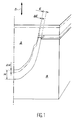
- FIGS. 1 to 4 the various stages of the manufacture of a hollow one-piece part are shown, constituted by a panel of substantially flat geometry, reinforced internally by stiffeners.
- This geometry constitutes only an example intended to illustrate in a simple way the method according to the invention.
- a tool which comprises a mold 10 formed by two half-molds 12 and 14, the facing surfaces 16 and 18 of which define an imprint complementary to the external shape of the part to be manufactured, when the two half-molds 12 and 14 are joined. More precisely, each of the half-molds 12 and 14 has a projecting peripheral rim terminated by a plane mechanical abutment surface 20, 22. These abutment surfaces 20 and 22 are arranged so that they can come to bear one against the other, as shown in Figures 2 and 3, to give the formed impression between the surfaces 16 and 18 a precise well-defined thickness.
- Pressure application means are associated with the mold 10 so as to allow a predetermined pressure to be applied to the two half-molds, until they come to bear. abutment surfaces 20 and 22 against each other.
- These pressure application means may in particular be constituted by a press or by any equivalent device capable of applying an appropriate pressure to the external faces of the half-molds 12 and 14 opposite their surfaces 16 and 18.
- the tool also includes heating means, not illustrated in the figure.
- These heating means can in particular be constituted by electrical resistances embedded in the half-molds 12 and 14 or by an oven or an equivalent device, in which the mold 10 is placed. They make it possible to raise the temperature inside this mold up to a value (for example, around 930 ° C.) compatible with the use of the SPF-DB technique.
- the thickness of the space delimited between these planar surfaces 17 and 19 is slightly less than the cumulative thickness of a stack of sheets 26 and a frame expandable 28 capable of being placed in this space.
- the stack of sheets 26 is intended to form the single piece that it is desired to manufacture.
- Welding barriers (not shown) are interposed between the different sheets 26 of the stack, at the locations for which welding of the sheets is not desired.
- the stack is formed of three sheets 26. A different number of sheets 26 can of course be used depending on the characteristics of the part that it is desired to produce.
- the expandable frame 28 is formed of two superposed sheets 30, previously welded together along a line 32 of continuous inner peripheral weld and along a line 34 of continuous outer peripheral weld.
- the line 34 of continuous external peripheral weld extends in the thickness of the stack of sheets 26, so as to ensure an initial relative positioning of the expandable frame 28 relative to the stack of sheets 26 as well as a relative initial positioning of the sheets of this stack.
- the continuous weld lines 32 and 34 define between the two sheets 30 of the expandable frame 28 an enclosed space 35 into which a pressurized gas can be injected through a passage 36 ( Figure 2). This gas injection inflates the expandable frame 28, as will be explained later.
- This welding barrier 38 has the function of preventing the welding of the adjacent sheets of the stack of sheets 26 and of the expandable frame 28 during inflation of the latter.
- a welding barrier can also be placed between the sheets 30 of the expandable frame 28, in the enclosed space 35.
- the expandable frame 28 constitutes one of the elements of the tool according to the invention.
- the tool according to the invention further comprises and in a known manner passages as illustrated at 40 and 42 in FIG. 3, making it possible to inject a gas under pressure in the appropriate regions inside the mold 10, so as to ensure the application of welding pressures by diffusion and superplastic forming.
- the arrangement of these passages 40 and 42 essentially depends on the geometry of the part that one wishes to produce. This arrangement, the development of which is familiar to users of SPF-DB techniques, is not part of the invention.
- the operator cuts the sheets 26 from which the one-piece piece is to be manufactured, so that the dimensions of these sheets slightly exceed the final dimensions of the piece.
- the operator also cuts the sheets 30 intended to form the expandable frame 28. Generally, this cutting is carried out so that the outer contour of the expandable frame 28 is substantially identical to the outer contour of the sheets 26. As will be explained later, the outer contour of the sheets 30 forming the expandable frame 28 may however have more complex shapes when the contour of the workpiece has recessed parts. Likewise, the inner contour of the sheets 30 intended to form the expandable frame 28 is cut so that these sheets 30 have a generally uniform width. In some cases, the inner contour of the sheets 30 may however have protruding parts, as will also be explained below.
- the inner 32 and outer 34 weld lines are made, after taking care to interpose the welding barrier 38 between the adjacent sheets 26 and 30 and appropriate welding barriers (not shown) between the sheets 26.
- the expandable frame 28 is formed and it constitutes, with the stack of sheets 26, a unitary assembly which can be placed between the two half-molds 12 and 14 after their opening.
- the peripheral region of the stack of sheets 26 as well as the expandable frame 28 are then placed between the surfaces 17 and 19 of the two half-molds 12 and 14. Under these conditions, the abutment surfaces 20 and 22 formed on these two half -mussels remain spaced from each other by a certain distance ( Figure 1).
- the heating means (not shown) are then used to raise the temperature in the mold 10 to the value necessary for forming. superplastic and diffusion welding.
- this temperature for example, approximately 930 ° C.
- a pressure sufficient to ensure diffusion welding is applied to the two half-molds 12 and 14, using the pressure means symbolized by the arrows 24. peripheral regions of the plates 26 which are then pinched between the surfaces 17 and 19 of the two half-molds.
- the temperature and pressure applied to the peripheral region of the stack of sheets 26 as well as to the expandable frame 28 have the effect of initiating the diffusion welding of the sheets 26 in this peripheral region. This results in a creep of the metal outwards and a reduction in the thickness of the sheets 26 in this peripheral region. This phenomenon continues until the abutment surfaces 20 and 22 come to bear, illustrated in FIG. 2.
- the expandable frame 28 is inflated by injection of a gas under pressure through the passage 36.
- the start of inflation can be controlled either in response to the signal delivered by a sensor detecting the contact between the surfaces 20 and 22, or by a time delay system implemented as soon as the pressure is applied to the half-molds 12 and 14.
- the inflation of the expandable frame 28 makes it possible to continue applying the pressure necessary for welding the sheets 26 by diffusion, in their peripheral region, after the abutment surfaces 20 and 22 have come into contact. voluntarily exaggerated in FIG. 2 the effect of this inflation on the sheets 26.
- pressurized gas into the expandable frame 28 continues for a time sufficient to ensure completion of the welding by diffusion of the sheets 26 in their peripheral region.
- first of all the diffusion welding of the different sheets 26 is carried out, in the zones to be welded situated inside the region. peripheral of the stack, by injection of gas under pressure through the passages 40.
- the superplastic forming is then carried out by injecting between the sheets 26 a gas under pressure through the passage 42.
- FIG. 4 represents the part obtained when these various operations are finished, after opening the mold 10. More precisely, it can be seen in this FIG. 4 that a simultaneous cutting of the sheets 26 and 30 along a cutting line 43 located inside of the outer peripheral welding line 34 34 and near this line simultaneously makes it possible to separate the expandable frame 28 from the part 44 and to carry out the final trimming of the latter.
- the expandable frame 28 thus constitutes a disposable tool.
- the superplastic forming of the part has the effect of pressing the outer sheets of the stack of sheets 26 against the surfaces 16 and 18 of the two half-molds 12 and 14 while the latter are in abutment against one another by their abutment surface 20 and 22. Consequently, the thickness of the part 44 obtained can be determined with great precision and perfectly reproducible.
- this advantage is particularly important when the one-piece part which it is desired to manufacture is not a planar or substantially planar panel but a part of curved shape, having a curvature which can be significant. .
- the half-mold 12 is in the form of a punch while the half-mold 14 is in the form of a matrix.
- the two surfaces 17 and 19 of these half-molds, between which the expandable frame 28 and the peripheral region of the stack of sheets 26 are pinched, are then strongly inclined relative to the direction of relative movement of the two half -moulds 12 and 14 under the action of the pressure means symbolized by the arrows 24.
- the abutment surfaces 20 and 22 remain flat surfaces oriented in a direction perpendicular to this direction of relative movement of the two half-molds.
- the tooling and the method according to the invention make it possible, as we have seen previously, to carry out superplastic forming by applying the external sheets of the stack of sheets 26 against surfaces 16 and 18 whose spacing is precisely fixed by the abutment of the abutment surfaces 20 and 22.
- the expandable frame 28 allows, as before, to complete the diffusion welding of the peripheral regions of the sheets 26, despite the disappearance of the pressure applied to these regions peripherals by the two half-molds when the abutment surfaces 20 and 22 come to bear against one another.
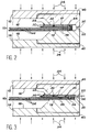
- FIGS. 6 and 7 There are shown by way of examples in FIGS. 6 and 7 two monobloc parts 44 capable of being manufactured by the method according to the invention.
- the part illustrated in FIG. 6 is a part having a strong curvature as well as a relatively smooth concave surface 46.
- the convex surface 48 of the part 44 obtained by superplastic forming, is protruding except on its peripheral region.
- the part 44 illustrated in FIG. 7 is a strongly curved part which has a projecting central part both on its convex face 48 and on its concave face 46.
- the rim of the projecting central parts can have a complex shape embodied here by a welding island 50.
- This welding island 50 extends towards the inside of the part the peripheral region in which all the sheets 26 are welded by diffusion.
- Such a shape can be obtained, in accordance with the invention, by giving the facing surfaces 16 and 18 of the two half-molds 12 and 14 the appropriate shapes and by extending inward the two sheets 30 forming the expandable frame 28, in order to produce the welding island 50 during the preliminary operation of welding the sheets in their peripheral region.
- the method according to the invention also makes it possible to manufacture one-piece parts having a tormented external contour, even in the case where the dimensions of a notch such as the notch 52 on FIG. 8 are too large for a diffusion welding of the different sheets 26 to be possible by the simple action of the pressure means 24 acting on the two half-molds 12 and 14.
- a stack of sheets 26 is placed in the mold having an outline without cutout and an expandable frame 28 of reduced and substantially uniform width is superimposed on this stack of sheets, which follows the outline of the part that is wants to manufacture.
- the shapes of the facing surfaces 16 and 18 of the half-molds 12 and 14 are then adapted to the shapes of the outline of the part to be manufactured.
- the expandable frame 28 After coming into abutment of the abutment surfaces 20 and 22 formed on the two half-molds, the expandable frame 28 is inflated according to the method described above. Due to the reduced width of the expandable frame 28, the pressure applied by this frame on the stack of sheets 26 is sufficient in all point to ensure efficient diffusion welding of the different sheets. When this welding is finished and thus delimits the final periphery of the part to be manufactured, the operations of superplastic forming and of diffusion welding are carried out in a conventional manner.
- the cutting of the sheets 26 of the stack and of the sheets 30 of the expandable frame 28 inside the outer peripheral weld line 34 (in broken lines in FIG. 8) and in the immediate vicinity of this line of welding makes it possible to obtain the one-piece part having the desired external profile.
- the cutting line 43 is illustrated in dashed lines in FIG. 8.
- the dimensioning of the part is therefore ensured with great precision and in a perfectly reproducible manner.
- the method and the tool in accordance with the invention can be used for the manufacture of parts of extremely varied dimensions and shapes.
- the number of sheets 26 of the stack initially placed in the mold can be any number greater than or equal to two.
Landscapes
- Engineering & Computer Science (AREA)
- Mechanical Engineering (AREA)
- Physics & Mathematics (AREA)
- Fluid Mechanics (AREA)
- Shaping Metal By Deep-Drawing, Or The Like (AREA)
- Pressure Welding/Diffusion-Bonding (AREA)
- Lining Or Joining Of Plastics Or The Like (AREA)
Abstract
Description
L'invention concerne principalement un procédé de fabrication d'une pièce monobloc à partir d'un empilement de tôles réalisée dans un métal tel qu'un alliage de titane permettant de mettre en oeuvre les techniques de formage superplastique et de soudage par diffusion, communément appelées techniques SPF-DB (de l'anglais "Superplastic Forming and Diffusion Bonding").The invention mainly relates to a method of manufacturing a single piece from a stack of sheets made of a metal such as a titanium alloy making it possible to implement the techniques of superplastic forming and diffusion welding, commonly called SPF-DB techniques (from English "Superplastic Forming and Diffusion Bonding").
L'invention concerne également un outillage permettant de mettre en oeuvre ce procédé.The invention also relates to a tool making it possible to implement this method.
Le procédé et l'outillage selon l'invention peuvent être utilisés dans tous les domaines d'application des techniques SPF-DB. Parmi ces domaines, on citera en particulier l'industrie aérospatiale.The method and the tooling according to the invention can be used in all fields of application of the SPF-DB techniques. Among these fields, the aerospace industry will be mentioned in particular.
Les techniques SPF-DB utilisent les propriétés de certains matériaux, tels que le titane et ses alliages de pouvoir s'allonger de façon permanente et importante sans risque de cassure, lorsqu'une pression est appliquée sur une tôle de ce matériau, à température élevée (environ 930°C). Cette technique utilise également l'aptitude des mêmes matériaux à se souder par diffusion dans les mêmes conditions de température et de pression.SPF-DB techniques use the properties of certain materials, such as titanium and its alloys, to be able to be permanently and significantly elongated without risk of breakage, when pressure is applied to a sheet of this material, at high temperature. (about 930 ° C). This technique also uses the ability of the same materials to weld by diffusion under the same conditions of temperature and pressure.
Plus précisément, la technique SPF-DB consiste à placer entre deux demi-moules un empilement de tôles dans lequel on a pris soin d'insérer des barrières de soudage entre les régions des tôles qui ne doivent pas être soudées. Après la fermeture du moule, on effectue généralement au moins une opération de soudage par diffusion et au moins une opération de formage superplastique. L'ordre et le nombre de ces opérations dépendent essentiellement des caractéristiques géométriques des pièces à fabriquer.More specifically, the SPF-DB technique consists of placing a stack between two half-molds of sheets in which care has been taken to insert welding barriers between the regions of the sheets which must not be welded. After closing the mold, at least one diffusion welding operation and at least one superplastic forming operation are generally carried out. The order and number of these operations depends essentially on the geometric characteristics of the parts to be manufactured.
Les opérations de soudage par diffusion consistent à chauffer les tôles et à appliquer sur celles-ci une pression assurant leur soudage dans les régions non protégées par une barrière de soudage. L'application de la pression de soudage se fait soit en injectant un gaz sous pression entre l'empilement de tôles et l'un des demi-moules, soit en injectant un gaz sous pression entre certaines des tôles, selon le type de soudage que l'on désire réaliser.Diffusion welding operations consist of heating the sheets and applying pressure thereon ensuring their welding in regions not protected by a welding barrier. The welding pressure is applied either by injecting a gas under pressure between the stack of sheets and one of the half-molds, or by injecting a gas under pressure between some of the sheets, depending on the type of welding that we want to achieve.
Les opérations de formage superplastique sont réalisées quant à elles en chauffant les tôles et en leur appliquant une pression de formage. A cet effet, on injecte un gaz sous pression entre les tôles de l'empilement. Cette injection de gaz à pour effet de plaquer les tôles contre les parois des deux demi-moules, sauf dans les régions préalablement soudées par diffusion, de façon à former des alvéoles.The superplastic forming operations are carried out by heating the sheets and applying a forming pressure to them. To this end, a pressurized gas is injected between the sheets of the stack. This gas injection has the effect of pressing the sheets against the walls of the two half-molds, except in the regions previously welded by diffusion, so as to form cells.
Le chauffage des tôles est effectué soit en utilisant un moule équipé de moyens de chauffage tels que des résistances chauffantes, soit en plaçant le moule dans un appareil de chauffage tel qu'un four.The heating of the sheets is carried out either by using a mold fitted with heating means such as heating resistors, or by placing the mold in a heating appliance such as an oven.
Pour que les opérations de soudage par diffusion et de formage superplastique puissent s'effectuer de façon satisfaisante, le gaz injecté ne doit pas pouvoir s'échapper du moule ou des alvéoles. Comme l'illustre notamment le document US-A-5 055 143, lorsque la pièce à fabriquer comporte une bordure sur toute sa périphérie, cette étanchéité est généralement obtenue en appliquant une pression sur les deux demi-moules, de façon à pincer entre eux la région périphérique de l'empilement de tôles. Cette opération est faite tout en chauffant les tôles, de telle sorte que l'obtention de l'étanchéité est accompagnée d'un soudage par diffusion des régions périphériques des tôles.For the diffusion welding and superplastic forming operations to be carried out satisfactorily, the injected gas must not be able to escape from the mold or the cells. As illustrated in particular by document US-A-5,055,143, when the workpiece has a border over its entire periphery, this seal is generally obtained by applying pressure to the two half-molds, so as to pinch the peripheral region of the stack of sheets. This is done while heating the sheets, so that obtaining the seal is accompanied by diffusion welding of the peripheral regions of the sheets.
Au cours de cette opération préliminaire à l'application de la technique SPF-DB, il se produit un fluage du métal vers l'extérieur entre les deux demi-moules, sur le bord périphérique de l'empilement de tôle. Ce fluage a pour conséquence une diminution de l'épaisseur de l'empilement de tôles dans sa région périphérique pincée entre les deux demi-moules. Ces derniers se rapprochent donc l'un de l'autre sur une distance indéterminée, qui dépend essentiellement du fluage des tôles. Par conséquent, l'écartement entre les deux demi-moules, qui détermine l'épaisseur de la pièce fabriquée, reste très imprécis.During this preliminary operation to the application of the SPF-DB technique, a creep of the metal towards the outside occurs between the two half-molds, on the peripheral edge of the sheet stack. This creep results in a reduction in the thickness of the stack of sheets in its peripheral region pinched between the two half-molds. The latter therefore approach each other over an indefinite distance, which essentially depends on the creep of the sheets. Consequently, the spacing between the two half-molds, which determines the thickness of the manufactured part, remains very imprecise.
Ce phénomène dû au fluage, déjà sensible sur des pièces sensiblement planes ou présentant un galbe très faible, s'accentue d'autant plus que le galbe ou la courbure de la pièce fabriquée augmente. En effet, à une variation relativement limitée de l'écartement entre les deux demi-moules dans la région périphérique correspond alors une variation d'autant plus importante de leur écartement dans la partie centrale du moule que la région périphérique est inclinée par rapport à la direction de déplacement relatif des demi-moules.This phenomenon due to creep, already noticeable on substantially flat parts or having a very low curve, becomes more marked the more the curve or the curvature of the manufactured part increases. In fact, a relatively limited variation in the spacing between the two half-molds in the peripheral region then corresponds to an even greater variation in their spacing in the central part of the mold that the peripheral region is inclined relative to the direction of relative movement of the mold halves.
Comme on l'a décrit en référence à la figure 4 dans le document US-A-5 055 143, on peut prévoir d'équiper les deux demi-moules de surfaces de butée mécaniques qui viennent en appui l'une contre l'autre lorsqu'on applique une pression sur ces deux demi-moules.As described with reference to FIG. 4 in document US-A-5,055,143, provision may be made to equip the two half-molds with mechanical abutment surfaces which come to bear against one another when applying pressure on these two half-molds.
Cependant, des essais ont montré que cette solution n'est pas satisfaisante. En effet, si elle permet bien de déterminer avec précision l'épaisseur de la pièce fabriquée, elle a pour conséquence que la pression exercée sur les zones périphériques des tôles est supprimée dès que les deux demi-moules arrivent en appui l'un contre l'autre. Par conséquent, le soudage des tôles par diffusion dans cette région périphérique est immédiatement interrompu. La qualité du soudage est donc mauvaise et ne permet pas d'assurer dans des conditions satisfaisantes la mise en oeuvre ultérieure de la technique SPF-DB.However, tests have shown that this solution is not satisfactory. Indeed, if it makes it possible to determine with precision the thickness of the manufactured part, it has the consequence that the pressure exerted on the peripheral zones of the sheets is removed as soon as the two half-molds come to bear one against the 'other. Consequently, the welding of the sheets by diffusion in this peripheral region is immediately interrupted. The quality of the welding is therefore poor and does not allow the satisfactory implementation of the SPF-DB technique to be carried out under satisfactory conditions.
Le document US-A-4 426 032 décrit également un procédé de fabrication mettant en oeuvre les techniques SPF-DB. Ce procédé se distingue notamment de celui qui est décrit dans le document US-A-5 055 143 par le fait que les deux demi-moules ne sont pas pressés l'un contre l'autre mais simplement liés l'un à l'autre par des boulons définissant entre eux un écartement maximal, et par le fait qu'une plaque de pression déformable est interposée entre l'un des demi-moules et un empilement de deux tôles destiné à former la pièce. L'étanchéité périphérique est assurée par un joint gonflable formé dans une région périphérique de l'empilement de tôles destinée à être découpée lors du détourage final de la pièce. Ce joint gonflable est réalisé en soudant les deux tôles de l'empilement selon deux lignes de soudure périphériques continues, espacées l'une de l'autre. Son gonflage a pour effet d'écarter les deux demi-moules pour les amener en appui contre les boulons qui les relient, et de plaquer une région périphérique de la plaque de pression contre le demi-moule adjacent à cette plaque. L'intérieur du moule est alors isolé de l'extérieur et les techniques SPF-DB peuvent être mises en oeuvre.Document US-A-4,426,032 also describes a manufacturing process using SPF-DB techniques. This process differs in particular from that which is described in document US-A-5,055,143 by the fact that the two half-molds are not pressed one against the other but simply linked to each other by bolts defining between them a maximum spacing, and by the fact that a deformable pressure plate is interposed between one of the half-molds and a stack of two sheets intended to form the part. The peripheral seal is ensured by an inflatable seal formed in a peripheral region of the stack of sheets intended to be cut during the final trimming of the part. This inflatable seal is produced by welding the two sheets of the stack according to two continuous peripheral weld lines, spaced from each other. Its inflation has the effect of spreading the two half-molds to bring them into abutment against the bolts which connect them, and of pressing a peripheral region of the pressure plate against the half-mold adjacent to this plate. The inside of the mold is then isolated from the outside and SPF-DB techniques can be used.
Dans ce procédé, le soudage par diffusion des plaques de l'empilement est obtenu en introduisant un gaz sous pression entre la plaque de pression et le demi-moule adjacent, de façon à presser les tôles de l'empilement entre la plaque de pression et l'autre demi-moule. L'épaisseur finale de la pièce dépend donc, comme dans le document US-A-5 055 143, du fluage du métal qui se produit lors de l'opération de soudage par diffusion.In this process, diffusion welding of the plates of the stack is obtained by introducing a pressurized gas between the pressure plate and the adjacent half-mold, so as to press the sheets of the stack between the pressure plate and the other half-mold. The final thickness of the part therefore depends, as in document US-A-5,055,143, on the creep of the metal which occurs during the diffusion welding operation.
De plus, le procédé décrit dans le document US-A-4 426 32 ne permet pas de réaliser simultanément l'étanchéité du moule et le soudage des tôles de l'empilement entre elles, par diffusion, dans la région périphérique.In addition, the method described in document US-A-4,426,32 does not make it possible to simultaneously seal the mold and weld the sheets of the stack to one another, by diffusion, in the peripheral region.
Enfin, la présence de la plaque de pression augmente le coût de l'outillage.Finally, the presence of the pressure plate increases the cost of the tool.
Par ailleurs, le document US-A-4 087 037 propose un procédé et un outillage de fabrication de pièces selon les techniques SPF-DB, dans lesquels les opérations de formage sont réalisées avant les opérations de soudage par diffusion, ce qui permet de supprimer les barrières de soudage habituellement placées dans l'empilement de tôles. Comme dans le document US-A-4 426 032, on interpose une plaque de pression déformable entre l'empilement de tôles et l'un des demi-moules et on maintient ces derniers l'un contre l'autre au moyen de pinces. L'application de la pression de soudage par diffusion est assurée au moyen d'une première vessie gonflable que l'on interpose entre la plaque de pression et le demi-moule adjacent. Pour empêcher le glissement des tôles lors du formage, une deuxième vessie gonflable, de forme annulaire peut être interposée entre une région périphérique de l'empilement de tôles et le demi-moule adjacent à la première vessie.Furthermore, document US-A-4 087 037 proposes a method and a tool for manufacturing parts according to SPF-DB techniques, in which the forming operations are carried out before the diffusion welding operations, which makes it possible to eliminate the welding barriers usually placed in the stack of sheets. As in document US-A-4 426 032, a deformable pressure plate is interposed between the stack of sheets and one of the half-molds and these are held against each other by means of pliers. The application of diffusion welding pressure is ensured by means of a first inflatable bladder which is interposed between the pressure plate and the adjacent half-mold. To prevent slipping of the sheets during forming, a second inflatable bladder, of annular shape can be interposed between a peripheral region of the stack of sheets and the half-mold adjacent to the first bladder.
Le procédé décrit dans ce document US-A-4 087 037 présente pratiquement les mêmes inconvénients que celui qui fait l'objet du document US-A-4 426 032.The process described in this document US-A-4 087 037 has practically the same drawbacks as that which is the subject of document US-A-4 426 032.
L'invention a pour objet un procédé et un outillage permettant de fabriquer une pièce monobloc par les techniques SPF-DB, d'une manière telle que l'épaisseur de la pièce obtenue soit maîtrisée avec une grande précision, aussi bien lorsque la pièce est relativement plane que lorsqu'elle présente une courbure ou un galbe important.The subject of the invention is a method and a tool making it possible to manufacture a single piece by SPF-DB techniques, in such a way that the thickness of the piece obtained is controlled with great precision, both when the piece is relatively flat only when it has a significant curvature or curve.
A cet effet, il est proposé un procédé de fabrication d'une pièce monobloc, par des techniques de formage superplastique et de soudage par diffusion, selon lequel on place un empilement de tôles entre deux demi-moules, on applique une pression sur ces deux demi-moules, de façon à pincer entre eux une région périphérique de l'empilement jusqu'à la venue en butée mécanique des deux demi-moules, et on applique, par injection de gaz entre les deux demi-moules, au moins une pression de soudage et de formage, pour obtenir ladite pièce monobloc, caractérisé par le fait qu'on place un cadre expansible entre la région périphérique de l'empilement de tôles et l'un des demi-moules, on pince ce cadre avec cette région périphérique entre les deux demi-moules, puis on gonfle le cadre expansible en maintenant les demi-moules en butée mécanique, de façon à souder les tôles par diffusion selon la région périphérique de l'empilement, avant d'appliquer la pression de soudage et de formage.To this end, a method of manufacturing a single piece is proposed, using superplastic forming and diffusion welding techniques, according to which a stack of sheets is placed between two half-molds, pressure is applied to these two. half-molds, so as to pinch a peripheral region of the stack between them until the two half-molds come into mechanical abutment, and at least one pressure is applied by injecting gas between the two half-molds welding and forming, to get said one-piece piece, characterized by the fact that an expandable frame is placed between the peripheral region of the sheet stack and one of the half-molds, this frame is clamped with this peripheral region between the two half-molds, then the expandable frame is inflated while maintaining the half-molds in mechanical abutment, so as to weld the sheets by diffusion along the peripheral region of the stack, before applying the welding and forming pressure.
Dans une forme de réalisation préférentielle de l'invention on utilise un cadre expansible formé de deux tôles superposées préalablement soudées selon des lignes de soudure périphériques intérieure et extérieure et on interpose une barrière de soudage entre le cadre et l'empilement.In a preferred embodiment of the invention, an expandable frame is used formed of two superimposed sheets previously welded along internal and external peripheral weld lines and a welding barrier is interposed between the frame and the stack.
De préférence, on soude alors simultanément les tôles de l'empilement et les tôles du cadre expansible selon la ligne de soudure périphérique extérieure.Preferably, the sheets of the stack and the sheets of the expandable frame are then welded simultaneously along the outer peripheral weld line.
Avantageusement, après avoir appliqué la pression de soudage et de formage, on sépare les deux demi-moules, puis on découpe simultanément la pièce obtenue et les tôles du cadre expansible à l'intérieur de la ligne de soudure périphérique extérieure, de façon à séparer le cadre expansible de la pièce obtenue et à réaliser simultanément un détourage final de cette dernière.Advantageously, after applying the welding and forming pressure, the two half-molds are separated, then the part obtained and the sheets of the expandable frame are cut simultaneously inside the outer peripheral weld line, so as to separate the expandable frame of the part obtained and to simultaneously carry out a final trimming of the latter.
Dans une forme de réalisation particulièrement avantageuse, on utilise deux demi- moules présentant respectivement une forme de poinçon et une forme de matrice.In a particularly advantageous embodiment, two half-molds are used which respectively have a punch shape and a die shape.
L'invention concerne également un outillage de fabrication d'une pièce monobloc, par des techniques de formage et de soudage par diffusion, comprenant deux demi-moules équipés de surfaces de butée mécaniques aptes à venir en appui les unes contre les autres, des moyens pour presser les deux demi-moules l'un contre l'autre jusqu'à la venue en appui des butées mécaniques, et des moyens d'injection de gaz entre les deux demi-moules, aptes à appliquer au moins une pression de soudage et de formage sur les tôles d'un empilement de tôles placé entre les deux demi-moules, pour obtenir une pièce monobloc, caractérisé par le fait qu'il comprend de plus un cadre expansible, apte à être placé entre une région périphérique de l'empilement de tôles et l'un des demi-moules, et des moyens pour gonfler ce cadre expansible.The invention also relates to a tool for manufacturing a single piece, using techniques forming and diffusion welding, comprising two half-molds equipped with mechanical abutment surfaces capable of coming into abutment against one another, means for pressing the two half-molds against one another until the coming to bear mechanical stops, and gas injection means between the two half-molds, capable of applying at least one welding and forming pressure on the sheets of a stack of sheets placed between the two half-molds , to obtain a single piece, characterized in that it further comprises an expandable frame, capable of being placed between a peripheral region of the stack of sheets and one of the half-molds, and means for inflating this expandable frame.
On décrira à présent, à titre d'exemples non limitatif, différents modes de mise en oeuvre de l'invention, en se référant aux dessins annexés, dans lesquels :
- les figure 1 à 3 sont des vues en coupe schématique illustrant trois étapes successives du procédé de fabrication selon l'invention, appliqué à la fabrication d'une pièce de géométrie sensiblement plane ;
- la figure 4 est une vue en perspective illustrant la dernière étape du procédé de fabrication illustré sur les figures 1 à 3 ;
- la figure 5 est une vue en coupe schématique comparable à la figure 3, illustrant une application du procédé selon l'invention a la fabrication d'une pièce galbée ;
- la figure 6 est une vue en perspective qui représente une pièce galbée obtenue par le procédé selon l'invention ;
- la figure 7 est une vue en perspective comparable à la figure 6, qui représente une autre pièce galbée obtenue par le procédé selon l'invention ; et
- la figure 8 est une vue en perspective illustrant un détail de la région périphérique d'une pièce de contour complexe obtenue par le procédé selon l'invention.
- Figures 1 to 3 are schematic sectional views illustrating three successive stages of the manufacturing process according to the invention, applied to the manufacture of a part of substantially planar geometry;
- Figure 4 is a perspective view illustrating the last step of the manufacturing process illustrated in Figures 1 to 3;
- Figure 5 is a schematic sectional view comparable to Figure 3, illustrating an application of the method according to the invention in the manufacture of a curved part;
- Figure 6 is a perspective view which shows a curved part obtained by the method according to the invention;
- Figure 7 is a perspective view comparable to Figure 6, which shows another curved part obtained by the method according to the invention; and
- FIG. 8 is a perspective view illustrating a detail of the peripheral region of a part with a complex contour obtained by the method according to the invention.
Sur les figures 1 à 4, on a représenté les différentes étapes de la fabrication d'une pièce creuse monobloc constituée par un panneau de géométrie sensiblement plane, renforcé intérieurement par des raidisseurs. Cette géométrie ne constitue qu'un exemple destiné à illustrer de façon simple le procédé selon l'invention.In FIGS. 1 to 4, the various stages of the manufacture of a hollow one-piece part are shown, constituted by a panel of substantially flat geometry, reinforced internally by stiffeners. This geometry constitutes only an example intended to illustrate in a simple way the method according to the invention.
Comme l'illustrent les figures 1 à 4, on utilise un outillage qui comprend un moule 10 formé de deux demi-moules 12 et 14 dont les surfaces 16 et 18 en vis-à-vis définissent une empreinte complémentaire de la forme extérieure de la pièce à fabriquer, lorsque les deux demi-moules 12 et 14 sont accolés. Plus précisément, chacun des demi-moules 12 et 14 comporte un rebord périphérique saillant terminé par une surface de butée mécanique plane 20, 22. Ces surfaces de butée 20 et 22 sont agencées de telle sorte qu'elles peuvent venir en appui l'une contre l'autre, comme l'illustrent les figures 2 et 3, pour donner à l'empreinte formée entre les surfaces 16 et 18 une épaisseur précise bien déterminée.As illustrated in FIGS. 1 to 4, a tool is used which comprises a
Des moyens d'application de pression, illustrés symboliquement par les flèches 24 sur les figures 1 à 3, sont associés au moule 10 de façon à permettre d'appliquer une pression prédéterminée sur les deux demi-moules, jusqu'à la venue en appui des surfaces de butée 20 et 22 l'une contre l'autre. Ces moyens d'application de pression peuvent notamment être constitués par une presse ou par tout dispositif équivalent susceptible d'appliquer une pression approprié sur les faces extérieures des demi-moules 12 et 14 opposées à leurs surfaces 16 et 18.Pressure application means, symbolically illustrated by the
L'outillage comprend également des moyens de chauffage, non illustrés sur la figure. Ces moyens de chauffage peuvent notamment être constitués par des résistances électriques noyées dans les demi-moules 12 et 14 ou par un four ou un dispositif équivalent, dans lequel est placé le moule 10. Ils permettent d'élever la température à l'intérieur de ce moule jusqu'à une valeur (par exemple, environ 930°C) compatible avec l'utilisation de la technique SPF-DB.The tool also includes heating means, not illustrated in the figure. These heating means can in particular be constituted by electrical resistances embedded in the half-
Les régions périphériques des surfaces 16 et 18 des demi-moules 12 et 14, situées au voisinage immédiat des surfaces de butée 20 et 22, forment des surfaces planes et parallèles 17 et 19, orientées perpendiculairement à la direction de déplacement des demi-moules 12 et 14 dans la forme de réalisation illustrée sur les figures 1 à 3. Lorsque les surfaces de butée 20 et 22 sont en appui l'une contre l'autre l'épaisseur de l'espace délimité entre ces surfaces planes 17 et 19 est légèrement inférieure à l'épaisseur cumulée d'un empilement de tôles 26 et d'un cadre expansible 28 susceptibles d'être placé dans cet espace.The peripheral regions of the
L'empilement de tôles 26 est destiné à former la pièce monobloc que l'on désire fabriquer. Des barrières de soudage (non représentées) sont interposées entre les différentes tôles 26 de l'empilement, aux emplacements pour lesquels un soudage des tôles n'est pas souhaité. Dans la forme de réalisation illustrée, l'empilement est formé de trois tôles 26. Un nombre de tôles 26 différent peut bien entendu être utilisé en fonction des caractéristiques de la pièce que l'on désire réaliser.The stack of
Le cadre expansible 28 est formé de deux tôles 30 superposées, préalablement soudées entre elles selon une ligne 32 de soudure périphérique intérieure continue et selon une ligne 34 de soudure périphérique extérieure continue. Dans la forme de réalisation représentée, la ligne 34 de soudure périphérique extérieure continue se prolonge dans l'épaisseur de l'empilement de tôles 26, de façon à assurer un positionnement initial relatif du cadre expansible 28 par rapport à l'empilement de tôles 26 ainsi qu'un positionnement initial relatif des tôles de cet empilement. Les lignes de soudure continues 32 et 34 définissent entre les deux tôles 30 du cadre expansible 28 un espace clos 35 dans lequel un gaz sous pression peut être injecté par un passage 36 (figure 2). Cette injection de gaz permet de gonfler le cadre expansible 28, comme on l'expliquera ultérieurement.The
Lors de la mise en place de l'empilement de tôles 26 et du cadre expansible 28 dans le moule 10, on prend soin d'interposer entre eux une barrière de soudage illustrée schématiquement en 38 sur les figures 1 à 3. Cette barrière de soudage 38 a pour fonction d'empêcher le soudage des tôles adjacentes de l'empilement de tôles 26 et du cadre expansible 28 lors du gonflage de ce dernier. Pour des raisons comparables, une barrière de soudage peut aussi être placée entre les tôles 30 du cadre expansible 28, dans l'espace clos 35.When placing the stack of
Bien qu'il soit associé à l'empilement de tôles 26 par la ligne 34 de soudure périphérique extérieure continue dans la forme de réalisation décrite, le cadre expansible 28 constitue l'un des élément de l'outillage conformément à l'invention.Although it is associated with the stack of
L'outillage conforme à l'invention comprend de plus et de façon connue des passages tels qu'illustrés en 40 et 42 sur la figure 3, permettant d'injecter un gaz sous pression dans les régions appropriées à l'intérieur du moule 10, de façon à assurer l'application des pressions de soudage par diffusion et de formage superplastique. L'agencement de ces passages 40 et 42 dépend essentiellement de la géométrie de la pièce que l'on désire réaliser. Cet agencement, dont la mise au point est familière aux utilisateurs des techniques SPF-DB, ne fait pas partie de l'invention.The tool according to the invention further comprises and in a known manner passages as illustrated at 40 and 42 in FIG. 3, making it possible to inject a gas under pressure in the appropriate regions inside the
La fabrication d'une pièce de géométrie sensiblement plane à l'aide de l'outillage qui vient d'être décrit va à présent être expliquée en se référant successivement aux figures 1 à 4.The manufacture of a part of substantially planar geometry using the tool which has just been described will now be explained with reference in turn to FIGS. 1 to 4.
Au cours d'une phase préliminaire, l'opérateur découpe les tôles 26 dans lesquelles doit être fabriquée la pièce monobloc, afin que les dimensions de ces tôles excèdent légèrement les dimensions finales de la pièce.During a preliminary phase, the operator cuts the
L'opérateur découpe également les tôles 30 destinées à former le cadre expansible 28. Généralement, ce découpage est réalisé de telle sorte que le contour extérieur du cadre expansible 28 soit sensiblement identique au contour extérieur des tôles 26. Comme on l'expliquera ultérieurement, le contour extérieur des tôles 30 formant le cadre expansible 28 peut toutefois présenter des formes plus complexes lorsque le contour de la pièce à fabriquer présente des parties en retrait. De même, le contour intérieur des tôles 30 destinées à former le cadre expansible 28 est découpé de façon telle que ces tôles 30 présentent une largeur généralement uniforme. Dans certains cas, le contour intérieur des tôles 30 peut toutefois présenter des parties en saillie, comme on l'expliquera également par la suite.The operator also cuts the
Lorsque la découpe des tôles 26 et 30 est terminée, on réalise les lignes de soudure périphériques intérieure 32 et extérieure 34, après avoir pris soin d'interposer la barrière de soudage 38 entre les tôles 26 et 30 adjacentes et des barrières de soudage appropriées (non représentées) entre les tôles 26. Lorsque cette opération est terminée, le cadre expansible 28 est formé et il constitue avec l'empilement de tôles 26 un ensemble unitaire qui peut être placé entre les deux demi-moules 12 et 14 après leur ouverture. La région périphérique de l'empilement de tôles 26 ainsi que le cadre expansible 28 sont alors placés entre les surfaces 17 et 19 des deux demi-moules 12 et 14. Dans ces conditions, les surfaces de butée 20 et 22 formées sur ces deux demi-moules restent écartées l'une de l'autre d'une certaine distance (figure 1).When the cutting of the
Les moyens de chauffage (non représentés) sont alors mis en oeuvre afin d'élever la température dans le moule 10 jusqu'à la valeur nécessaire au formage superplastique et au soudage par diffusion. Lorsque cette température (par exemple, environ 930°C) est atteinte, on applique sur les deux demi-moules 12 et 14, à l'aide des moyens de pression symbolisés par les flèches 24, une pression suffisante pour assurer le soudage par diffusion des régions périphériques des plaques 26 qui sont alors pincées entre les surfaces 17 et 19 des deux demi-moules.The heating means (not shown) are then used to raise the temperature in the
La température et la pression appliquées sur la région périphérique de l'empilement de tôles 26 ainsi que sur le cadre expansible 28 ont pour effet d'amorcer le soudage par diffusion des tôles 26 dans cette région périphérique. Cela se traduit par un fluage du métal vers l'extérieur et par une réduction de l'épaisseur des tôles 26 dans cette région périphérique. Ce phénomène se poursuit jusqu'à la venue en appui des surfaces de butée 20 et 22, illustrée sur la figure 2.The temperature and pressure applied to the peripheral region of the stack of
Dès la venue en appui des surfaces de butée 20 et 22 ou même avant, le cadre expansible 28 est gonflé par injection d'un gaz sous pression au travers du passage 36. Selon le cas, le début du gonflage peut être commandé soit en réponse au signal délivré par un capteur détectant le contact entre les surfaces 20 et 22, soit par un système de temporisation mis en oeuvre dès l'application de la pression sur les demi-moules 12 et 14.As soon as the abutment surfaces 20 and 22 come into abutment or even before, the
Le gonflage du cadre expansible 28 permet de poursuivre l'application de la pression nécessaire au soudage des tôles 26 par diffusion, dans leur région périphérique, après la venue en contact des surfaces de butée 20 et 22. On a illustré schématiquement et de façon volontairement exagérée sur la figure 2 l'effet de ce gonflage sur les tôles 26.The inflation of the
L'introduction de gaz sous pression dans le cadre expansible 28 se poursuit pendant un temps suffisant pour assurer un achèvement du soudage par diffusion des tôles 26 dans leur région périphérique.The introduction of pressurized gas into the
Lorsque ce soudage est terminé, les opérations classiques de formage superplastique et de soudage par diffusion, qui dépendent essentiellement de la forme de la pièce monobloc que l'on désire fabriquer, sont mises en oeuvre.When this welding is finished, the conventional operations of superplastic forming and diffusion welding, which essentially depend on the shape of the one-piece part which it is desired to manufacture, are implemented.
Ainsi et uniquement à titre d'exemple, dans la forme de réalisation illustrée sur les figures 1 à 4, on réalise tout d'abord le soudage par diffusion des différentes tôles 26, dans les zones à souder situées à l'intérieur de la région périphérique de l'empilement, par injection de gaz sous pression par les passages 40. Le formage superplastique est ensuite effectué en injectant entre les tôles 26 un gaz sous pression par le passage 42.Thus and only by way of example, in the embodiment illustrated in FIGS. 1 to 4, first of all the diffusion welding of the
La figure 4 représente la pièce obtenue lorsque ces différentes opérations sont terminées, après ouverture du moule 10. Plus précisément, on voit sur cette figure 4 qu'une découpe simultanée des tôles 26 et 30 selon une ligne de découpe 43 située à l'intérieur de la ligne 34 de soudure périphérique extérieure 34 et à proximité de cette ligne permet simultanément de séparer le cadre expansible 28 de la pièce 44 et de réaliser le détourage final de cette dernière. Le cadre expansible 28 constitue ainsi un outil jetable.FIG. 4 represents the part obtained when these various operations are finished, after opening the
La description qui précède fait apparaître clairement que le formage superplastique de la pièce a pour effet de plaquer les tôles extérieures de l'empilement de tôles 26 contre les surfaces 16 et 18 des deux demi-moules 12 et 14 alors que ces derniers sont en appui l'un contre l'autre par leur surface de butée 20 et 22. Par conséquent, l'épaisseur de la pièce 44 obtenue peut être déterminée avec une très grande précision et de façon parfaitement reproductible.The above description clearly shows that the superplastic forming of the part has the effect of pressing the outer sheets of the stack of
Comme on l'a illustré sur la figure 5, cet avantage est particulièrement important lorsque la pièce monobloc que l'on désire fabriquer n'est pas un panneau plan ou sensiblement plan mais une pièce de forme galbée, présentant une courbure qui peut être importante.As illustrated in FIG. 5, this advantage is particularly important when the one-piece part which it is desired to manufacture is not a planar or substantially planar panel but a part of curved shape, having a curvature which can be significant. .
Dans ce cas, on voit sur la figure 5 que le demi-moule 12 se présente sous la forme d'un poinçon alors que le demi-moule 14 se présente sous la forme d'une matrice. Les deux surfaces 17 et 19 de ces demi-moules, entre lesquelles sont pincés à la fois le cadre expansible 28 et la région périphérique de l'empilement de tôles 26, sont alors fortement inclinées par rapport à la direction de déplacement relative des deux demi-moules 12 et 14 sous l'action des moyens de pression symbolisés par les flèches 24. En revanche les surfaces de butée 20 et 22 restent des surfaces planes orientées selon une direction perpendiculaire à cette direction de déplacement relatif des deux demi-moules.In this case, it can be seen in FIG. 5 that the half-
En l'absence des surfaces de butée 20 et 22 et du cadre expansible 28 selon l'invention, on comprend qu'une variation relativement faible de l'écartement entre les surfaces 17 et 19, résultant du fluage des tôles 26 lors de l'opération préliminaire de soudage par diffusion de la région périphérique de l'empilement de tôles 26, se traduirait par un déplacement relatif sensiblement plus important entre les parties des surfaces 16 et 18 sensiblement perpendiculaires à la direction de déplacement des deux demi-moules.In the absence of the abutment surfaces 20 and 22 and of the
Au contraire, l'outillage et le procédé selon l'invention permettent, comme on l'a vu précédemment, de réaliser le formage superplastique en appliquant les tôles extérieures de l'empilement de tôles 26 contre des surfaces 16 et 18 dont l'écartement est fixé avec précision par la venue en appui des surfaces de butée 20 et 22. Le cadre expansible 28 permet, comme précédemment, d'achever le soudage par diffusion des régions périphériques des tôles 26, malgré la disparition de la pression appliquée sur ces régions périphériques par les deux demi-moules lorsque les surfaces de butée 20 et 22 viennent en appui l'une contre l'autre.On the contrary, the tooling and the method according to the invention make it possible, as we have seen previously, to carry out superplastic forming by applying the external sheets of the stack of
On a représenté à titre d'exemples sur les figures 6 et 7 deux pièces monobloc 44 susceptibles d'être fabriquées par le procédé selon l'invention.There are shown by way of examples in FIGS. 6 and 7 two
La pièce illustrée sur la figure 6 est une pièce présentant une forte courbure ainsi qu'une surface concave 46 relativement lisse. En revanche, la surface convexe 48 de la pièce 44, obtenue par le formage superplastique, est en saillie sauf sur sa région périphérique.The part illustrated in FIG. 6 is a part having a strong curvature as well as a relatively smooth
La pièce 44 illustrée sur la figure 7 est une pièce fortement incurvée qui présente une partie centrale en saillie aussi bien sur sa face convexe 48 que sur sa face concave 46.The
Afin d'illustrer les possibilités offertes par le procédé selon l'invention, on voit sur la figure 7 que le rebord des parties centrales en saillie peut présenter une forme complexe matérialisée ici par un îlot de soudage 50. Cet îlot de soudage 50 prolonge vers l'intérieur de la pièce la région périphérique dans laquelle toutes les tôles 26 sont soudées par diffusion. Une telle forme peut être obtenue, conformément à l'invention, en donnant aux surfaces en vis-à-vis 16 et 18 des deux demi-moules 12 et 14 les formes appropriées et en prolongeant vers l'intérieur les deux tôles 30 formant le cadre expansible 28, afin de réaliser l'îlot de soudage 50 au cours de l'opération préliminaire de soudage des tôles dans leur région périphérique.In order to illustrate the possibilities offered by the method according to the invention, it can be seen in FIG. 7 that the rim of the projecting central parts can have a complex shape embodied here by a
Enfin et comme on l'a illustré sur la figure 8, le procédé selon l'invention permet aussi de fabriquer des pièces monobloc présentant un contour extérieur tourmenté, même dans le cas où les dimensions d'une entaille telle que l'entaille 52 sur la figure 8 sont trop grandes pour qu'un soudage par diffusion des différentes tôles 26 soit possible par la simple action des moyens de pression 24 agissant sur les deux demi-moules 12 et 14.Finally and as illustrated in FIG. 8, the method according to the invention also makes it possible to manufacture one-piece parts having a tormented external contour, even in the case where the dimensions of a notch such as the
Dans ce cas, on place dans le moule un empilement de tôles 26 présentant un contour dépourvu de découpe et on superpose à cet empilement de tôles un cadre expansible 28 de largeur réduite et sensiblement uniforme, qui suit le contour de la pièce que l'on désire fabriquer. Les formes des surfaces en vis-à-vis 16 et 18 des demi-moules 12 et 14 sont alors adaptées aux formes du contour de la pièce à fabriquer.In this case, a stack of
Après la venue en appui des surfaces de butée 20 et 22 formées sur les deux demi-moules, on gonfle le cadre expansible 28 conformément au procédé décrit précédemment. Du fait de la largeur réduite du cadre expansible 28, la pression appliquée par ce cadre sur l'empilement de tôles 26 est suffisante en tout point pour assurer un soudage par diffusion efficace des différentes tôles. Lorsque ce soudage est terminé et délimite ainsi la périphérie définitive de la pièce à fabriquer, les opérations de formage superplastique et de soudage par diffusion sont mises en oeuvre de façon classique.After coming into abutment of the abutment surfaces 20 and 22 formed on the two half-molds, the
Après ouverture du moule, la découpe des tôles 26 de l'empilement et des tôles 30 du cadre expansible 28 à l'intérieur de la ligne de soudure périphérique extérieure 34 (en traits discontinus sur la figure 8) et à proximité immédiate de cette ligne de soudure permet d'obtenir la pièce monobloc présentant le profil extérieur désiré. La ligne de découpe 43 est illustrée en traits mixtes sur la figure 8. Ici encore, le dimensionnement de la pièce est donc assuré avec une grande précision et de façon parfaitement reproductible.After opening the mold, the cutting of the
Bien entendu, le procédé et l'outillage conformes à l'invention peuvent être utilisés pour la fabrication de pièces de dimensions et de formes extrêmement variées. Selon la géométrie de ces pièces et de façon classique dans l'utilisation des techniques de formage superplastique et de soudage par diffusion, le nombre des tôles 26 de l'empilement placé initialement dans le moule peut être un nombre quelconque supérieur ou égal à deux.Of course, the method and the tool in accordance with the invention can be used for the manufacture of parts of extremely varied dimensions and shapes. Depending on the geometry of these parts and conventionally in the use of superplastic forming and diffusion welding techniques, the number of
Claims (9)
Applications Claiming Priority (2)
| Application Number | Priority Date | Filing Date | Title |
|---|---|---|---|
| FR9605249 | 1996-04-25 | ||
| FR9605249A FR2747949B1 (en) | 1996-04-25 | 1996-04-25 | PROCESS AND TOOLS FOR MANUFACTURING A ONE-PIECE PART BY SUPERPLASTIC FORMING AND DIFFUSION WELDING TECHNIQUES |
Publications (2)
| Publication Number | Publication Date |
|---|---|
| EP0803301A1 true EP0803301A1 (en) | 1997-10-29 |
| EP0803301B1 EP0803301B1 (en) | 2001-03-28 |
Family
ID=9491594
Family Applications (1)
| Application Number | Title | Priority Date | Filing Date |
|---|---|---|---|
| EP19970400905 Expired - Lifetime EP0803301B1 (en) | 1996-04-25 | 1997-04-22 | Method of manufacturing an article by superplastic forming and diffusion bonding |
Country Status (4)
| Country | Link |
|---|---|
| EP (1) | EP0803301B1 (en) |
| DE (1) | DE69704388T2 (en) |
| ES (1) | ES2159381T3 (en) |
| FR (1) | FR2747949B1 (en) |
Cited By (3)
| Publication number | Priority date | Publication date | Assignee | Title |
|---|---|---|---|---|
| CN113333935A (en) * | 2021-04-30 | 2021-09-03 | 成都飞机工业(集团)有限责任公司 | Curved web surface titanium alloy superplastic forming-diffusion bonding blank preparation method |
| CN114571190A (en) * | 2022-03-08 | 2022-06-03 | 中国航空制造技术研究院 | SPF/DB hollow structure forming method |
| WO2024028552A1 (en) * | 2022-08-02 | 2024-02-08 | Safran Nacelles | Method for manufacturing ducts for a heat exchanger |
Families Citing this family (1)
| Publication number | Priority date | Publication date | Assignee | Title |
|---|---|---|---|---|
| CN101912919B (en) * | 2010-07-16 | 2012-04-25 | 沈阳黎明航空发动机(集团)有限责任公司 | Composite forming method of gas bulging forming and thermal forming and device used by same |
Citations (3)
| Publication number | Priority date | Publication date | Assignee | Title |
|---|---|---|---|---|
| US4087037A (en) * | 1976-07-09 | 1978-05-02 | Mcdonnell Douglas Corporation | Method of and tools for producing superplastically formed and diffusion bonded structures |
| JPS6297782A (en) * | 1985-10-23 | 1987-05-07 | Kawasaki Heavy Ind Ltd | Joining and forming method for metallic plate |
| US5055143A (en) * | 1990-03-26 | 1991-10-08 | Mcdonnell Douglas Corporation | Re-entrant angle closure on superplastically formed structure |
-
1996
- 1996-04-25 FR FR9605249A patent/FR2747949B1/en not_active Expired - Fee Related
-
1997
- 1997-04-22 DE DE1997604388 patent/DE69704388T2/en not_active Expired - Lifetime
- 1997-04-22 ES ES97400905T patent/ES2159381T3/en not_active Expired - Lifetime
- 1997-04-22 EP EP19970400905 patent/EP0803301B1/en not_active Expired - Lifetime
Patent Citations (3)
| Publication number | Priority date | Publication date | Assignee | Title |
|---|---|---|---|---|
| US4087037A (en) * | 1976-07-09 | 1978-05-02 | Mcdonnell Douglas Corporation | Method of and tools for producing superplastically formed and diffusion bonded structures |
| JPS6297782A (en) * | 1985-10-23 | 1987-05-07 | Kawasaki Heavy Ind Ltd | Joining and forming method for metallic plate |
| US5055143A (en) * | 1990-03-26 | 1991-10-08 | Mcdonnell Douglas Corporation | Re-entrant angle closure on superplastically formed structure |
Non-Patent Citations (1)
| Title |
|---|
| PATENT ABSTRACTS OF JAPAN vol. 011, no. 310 (M - 630) 9 October 1987 (1987-10-09) * |
Cited By (4)
| Publication number | Priority date | Publication date | Assignee | Title |
|---|---|---|---|---|
| CN113333935A (en) * | 2021-04-30 | 2021-09-03 | 成都飞机工业(集团)有限责任公司 | Curved web surface titanium alloy superplastic forming-diffusion bonding blank preparation method |
| CN114571190A (en) * | 2022-03-08 | 2022-06-03 | 中国航空制造技术研究院 | SPF/DB hollow structure forming method |
| WO2024028552A1 (en) * | 2022-08-02 | 2024-02-08 | Safran Nacelles | Method for manufacturing ducts for a heat exchanger |
| FR3138689A1 (en) * | 2022-08-02 | 2024-02-09 | Safran Nacelles | Process for manufacturing pipes for a heat exchanger |
Also Published As
| Publication number | Publication date |
|---|---|
| EP0803301B1 (en) | 2001-03-28 |
| FR2747949A1 (en) | 1997-10-31 |
| FR2747949B1 (en) | 1998-07-17 |
| DE69704388D1 (en) | 2001-05-03 |
| ES2159381T3 (en) | 2001-10-01 |
| DE69704388T2 (en) | 2001-10-31 |
Similar Documents
| Publication | Publication Date | Title |
|---|---|---|
| EP0015202B1 (en) | Annular gasket for use in the casting of ophthalmic or optical lenses of organic material, and method of using such a gasket | |
| EP0894046B1 (en) | Method for making a finished part comprising a zone for providing a passage, finished part and corresponding assembly | |
| FR2806347A1 (en) | Manufacture of bath, shower tray, etc. from thermoplastic material with cellular core in single stamping operation without stretching or tearing of material | |
| EP3178631B1 (en) | Suction thermoforming mould device, manufacturing method implementing same and manufactured element | |
| EP1171272B1 (en) | Forming equipment for polymerisation of shaped parts in composite material | |
| EP0380894B1 (en) | Device for deep-drawing sheet materials | |
| EP1382436B1 (en) | Method for moulding a composite article and moulding apparatus for carrying out said method | |
| EP2111333B1 (en) | Method of fastening first and second thermoplastic parts | |
| CA2475024C (en) | Method for the production of parts by means of diffusion bonding and superplastic forming, and mold for carrying out said method | |
| EP1190786B1 (en) | Method of hydroforming of plates and apparatus for carrying out the same | |
| EP0803301B1 (en) | Method of manufacturing an article by superplastic forming and diffusion bonding | |
| EP0433203B1 (en) | Method and apparatus for drawing conical containers and containers so obtained | |
| FR2692504A1 (en) | Warm drawing of steel sheet into complex shapes - using appts. that rapidly heats localised areas of blank, so reducing operating cycle | |
| EP2955000A1 (en) | Thermoforming mould device and method for manufacturing same and manufactured trim element | |
| WO1999041058A1 (en) | Method for folding sections comprising a hollow body and a coating sheet, and resulting folded section | |
| EP0707533B1 (en) | Method for the manufacture of a multilayered object by moulding and mould for the manufacture of such an object | |
| EP1125720A1 (en) | Process and apparatus for making a decorated object | |
| FR2754199A1 (en) | Fabrication of a component incorporating a closed cavity by super-plastic forming and diffusion bonding | |
| EP1095840B1 (en) | Steering wheel for motor vehicle and method for its manufacture | |
| WO2000050182A1 (en) | Crimping ring, method for making same and manufacturing installation | |
| WO2026022308A1 (en) | Thermocompression method for manufacturing a part made of a composite material having a thermoplastic polymer matrix | |
| FR2866827A1 (en) | Procedure for covering a rigid component with a supple/decorative layer, e.g. for vehicle interior trim, uses supporting frame and air extraction | |
| FR2543130A1 (en) | Process and mould for curving a thin glass sheet and thin glass sheet thus curved | |
| FR2845309A1 (en) | Thermoforming mould e.g. for motor vehicle interior carpet has blank holder in form of upper and lower pressure elements | |
| FR2705580A1 (en) | Method for manufacturing a ski having a shell |
Legal Events
| Date | Code | Title | Description |
|---|---|---|---|
| PUAI | Public reference made under article 153(3) epc to a published international application that has entered the european phase |
Free format text: ORIGINAL CODE: 0009012 |
|
| AK | Designated contracting states |
Kind code of ref document: A1 Designated state(s): BE DE ES GB IT NL |
|
| 17P | Request for examination filed |
Effective date: 19980402 |
|
| GRAG | Despatch of communication of intention to grant |
Free format text: ORIGINAL CODE: EPIDOS AGRA |
|
| 17Q | First examination report despatched |
Effective date: 20000616 |
|
| GRAG | Despatch of communication of intention to grant |
Free format text: ORIGINAL CODE: EPIDOS AGRA |
|
| GRAH | Despatch of communication of intention to grant a patent |
Free format text: ORIGINAL CODE: EPIDOS IGRA |
|
| GRAH | Despatch of communication of intention to grant a patent |
Free format text: ORIGINAL CODE: EPIDOS IGRA |
|
| GRAA | (expected) grant |
Free format text: ORIGINAL CODE: 0009210 |
|
| AK | Designated contracting states |
Kind code of ref document: B1 Designated state(s): BE DE ES GB IT NL |
|
| ITF | It: translation for a ep patent filed | ||
| REF | Corresponds to: |
Ref document number: 69704388 Country of ref document: DE Date of ref document: 20010503 |
|
| GBT | Gb: translation of ep patent filed (gb section 77(6)(a)/1977) |
Effective date: 20010503 |
|
| RAP2 | Party data changed (patent owner data changed or rights of a patent transferred) |
Owner name: AEROSPATIALE MATRA |
|
| RAP2 | Party data changed (patent owner data changed or rights of a patent transferred) |
Owner name: MATRA HAUTES TECHNOLOGIES |
|
| REG | Reference to a national code |
Ref country code: ES Ref legal event code: FG2A Ref document number: 2159381 Country of ref document: ES Kind code of ref document: T3 |
|
| RAP2 | Party data changed (patent owner data changed or rights of a patent transferred) |
Owner name: AEROSPATIALE MATRA TECHNOLOGIES |
|
| RAP2 | Party data changed (patent owner data changed or rights of a patent transferred) |
Owner name: EUROPEAN AERONAUTIC DEFENCE AND SPACE COMPANY - EA |
|
| NLT2 | Nl: modifications (of names), taken from the european patent patent bulletin |
Owner name: AEROSPATIALE MATRA |
|
| NLT2 | Nl: modifications (of names), taken from the european patent patent bulletin |
Owner name: AEROSPATIALE MATRA TECHNOLOGIES;EUROPEAN AERONAUTI |
|
| REG | Reference to a national code |
Ref country code: GB Ref legal event code: IF02 |
|
| PLBE | No opposition filed within time limit |
Free format text: ORIGINAL CODE: 0009261 |
|
| STAA | Information on the status of an ep patent application or granted ep patent |
Free format text: STATUS: NO OPPOSITION FILED WITHIN TIME LIMIT |
|
| 26N | No opposition filed | ||
| REG | Reference to a national code |
Ref country code: ES Ref legal event code: PC2A |
|
| PGFP | Annual fee paid to national office [announced via postgrant information from national office to epo] |
Ref country code: NL Payment date: 20050403 Year of fee payment: 9 |
|
| PG25 | Lapsed in a contracting state [announced via postgrant information from national office to epo] |
Ref country code: NL Free format text: LAPSE BECAUSE OF NON-PAYMENT OF DUE FEES Effective date: 20061101 |
|
| NLV4 | Nl: lapsed or anulled due to non-payment of the annual fee |
Effective date: 20061101 |
|
| PGFP | Annual fee paid to national office [announced via postgrant information from national office to epo] |
Ref country code: ES Payment date: 20100427 Year of fee payment: 14 |
|
| PGFP | Annual fee paid to national office [announced via postgrant information from national office to epo] |
Ref country code: IT Payment date: 20100426 Year of fee payment: 14 Ref country code: DE Payment date: 20100423 Year of fee payment: 14 |
|
| PGFP | Annual fee paid to national office [announced via postgrant information from national office to epo] |
Ref country code: BE Payment date: 20100419 Year of fee payment: 14 |
|
| PGFP | Annual fee paid to national office [announced via postgrant information from national office to epo] |
Ref country code: GB Payment date: 20100420 Year of fee payment: 14 |
|
| BERE | Be: lapsed |
Owner name: EUROPEAN AERONAUTIC DEFENCE AND SPACE CY *EADS FRA Effective date: 20110430 |
|
| REG | Reference to a national code |
Ref country code: DE Ref legal event code: R119 Ref document number: 69704388 Country of ref document: DE |
|
| REG | Reference to a national code |
Ref country code: DE Ref legal event code: R119 Ref document number: 69704388 Country of ref document: DE |
|
| GBPC | Gb: european patent ceased through non-payment of renewal fee |
Effective date: 20110422 |
|
| PG25 | Lapsed in a contracting state [announced via postgrant information from national office to epo] |
Ref country code: BE Free format text: LAPSE BECAUSE OF NON-PAYMENT OF DUE FEES Effective date: 20110430 |
|
| PG25 | Lapsed in a contracting state [announced via postgrant information from national office to epo] |
Ref country code: IT Free format text: LAPSE BECAUSE OF NON-PAYMENT OF DUE FEES Effective date: 20110422 Ref country code: GB Free format text: LAPSE BECAUSE OF NON-PAYMENT OF DUE FEES Effective date: 20110422 |
|
| REG | Reference to a national code |
Ref country code: ES Ref legal event code: FD2A Effective date: 20120604 |
|
| PG25 | Lapsed in a contracting state [announced via postgrant information from national office to epo] |
Ref country code: ES Free format text: LAPSE BECAUSE OF NON-PAYMENT OF DUE FEES Effective date: 20110423 |
|
| PG25 | Lapsed in a contracting state [announced via postgrant information from national office to epo] |
Ref country code: DE Free format text: LAPSE BECAUSE OF NON-PAYMENT OF DUE FEES Effective date: 20111031 |