EP2955000A1 - Thermoforming mould device and method for manufacturing same and manufactured trim element - Google Patents
Thermoforming mould device and method for manufacturing same and manufactured trim element Download PDFInfo
- Publication number
- EP2955000A1 EP2955000A1 EP15305881.3A EP15305881A EP2955000A1 EP 2955000 A1 EP2955000 A1 EP 2955000A1 EP 15305881 A EP15305881 A EP 15305881A EP 2955000 A1 EP2955000 A1 EP 2955000A1
- Authority
- EP
- European Patent Office
- Prior art keywords
- mold
- sheet
- forming
- suction
- parts
- Prior art date
- Legal status (The legal status is an assumption and is not a legal conclusion. Google has not performed a legal analysis and makes no representation as to the accuracy of the status listed.)
- Granted
Links
- 238000003856 thermoforming Methods 0.000 title claims abstract description 5
- 238000004519 manufacturing process Methods 0.000 title claims description 23
- 238000000034 method Methods 0.000 title claims description 12
- 230000002093 peripheral effect Effects 0.000 claims abstract description 10
- 239000012815 thermoplastic material Substances 0.000 claims abstract description 7
- 230000003252 repetitive effect Effects 0.000 claims description 8
- 239000004033 plastic Substances 0.000 claims description 5
- 229920003023 plastic Polymers 0.000 claims description 5
- 238000003825 pressing Methods 0.000 claims description 4
- 230000001629 suppression Effects 0.000 claims description 4
- 230000000295 complement effect Effects 0.000 claims description 3
- 230000002457 bidirectional effect Effects 0.000 claims description 2
- 230000006835 compression Effects 0.000 claims description 2
- 238000007906 compression Methods 0.000 claims description 2
- 230000000694 effects Effects 0.000 claims description 2
- 238000005520 cutting process Methods 0.000 claims 1
- 238000006073 displacement reaction Methods 0.000 description 4
- 238000007666 vacuum forming Methods 0.000 description 3
- 238000000605 extraction Methods 0.000 description 2
- 239000000463 material Substances 0.000 description 2
- -1 polyethylene Polymers 0.000 description 2
- 239000004698 Polyethylene Substances 0.000 description 1
- 239000004743 Polypropylene Substances 0.000 description 1
- 238000004873 anchoring Methods 0.000 description 1
- 238000010276 construction Methods 0.000 description 1
- 238000001816 cooling Methods 0.000 description 1
- 230000003116 impacting effect Effects 0.000 description 1
- 238000012986 modification Methods 0.000 description 1
- 230000004048 modification Effects 0.000 description 1
- 239000002985 plastic film Substances 0.000 description 1
- 229920000573 polyethylene Polymers 0.000 description 1
- 229920001155 polypropylene Polymers 0.000 description 1
- 229920000915 polyvinyl chloride Polymers 0.000 description 1
- 239000004800 polyvinyl chloride Substances 0.000 description 1
- 238000007789 sealing Methods 0.000 description 1
- 238000006467 substitution reaction Methods 0.000 description 1
- 229920001169 thermoplastic Polymers 0.000 description 1
- 239000004416 thermosoftening plastic Substances 0.000 description 1
Images


Classifications
-
- B—PERFORMING OPERATIONS; TRANSPORTING
- B29—WORKING OF PLASTICS; WORKING OF SUBSTANCES IN A PLASTIC STATE IN GENERAL
- B29C—SHAPING OR JOINING OF PLASTICS; SHAPING OF MATERIAL IN A PLASTIC STATE, NOT OTHERWISE PROVIDED FOR; AFTER-TREATMENT OF THE SHAPED PRODUCTS, e.g. REPAIRING
- B29C51/00—Shaping by thermoforming, i.e. shaping sheets or sheet like preforms after heating, e.g. shaping sheets in matched moulds or by deep-drawing; Apparatus therefor
- B29C51/26—Component parts, details or accessories; Auxiliary operations
- B29C51/30—Moulds
- B29C51/36—Moulds specially adapted for vacuum forming, Manufacture thereof
-
- B—PERFORMING OPERATIONS; TRANSPORTING
- B29—WORKING OF PLASTICS; WORKING OF SUBSTANCES IN A PLASTIC STATE IN GENERAL
- B29C—SHAPING OR JOINING OF PLASTICS; SHAPING OF MATERIAL IN A PLASTIC STATE, NOT OTHERWISE PROVIDED FOR; AFTER-TREATMENT OF THE SHAPED PRODUCTS, e.g. REPAIRING
- B29C51/00—Shaping by thermoforming, i.e. shaping sheets or sheet like preforms after heating, e.g. shaping sheets in matched moulds or by deep-drawing; Apparatus therefor
- B29C51/08—Deep drawing or matched-mould forming, i.e. using mechanical means only
- B29C51/082—Deep drawing or matched-mould forming, i.e. using mechanical means only by shaping between complementary mould parts
- B29C51/087—Deep drawing or matched-mould forming, i.e. using mechanical means only by shaping between complementary mould parts with at least one of the mould parts comprising independently movable sections
-
- B—PERFORMING OPERATIONS; TRANSPORTING
- B29—WORKING OF PLASTICS; WORKING OF SUBSTANCES IN A PLASTIC STATE IN GENERAL
- B29C—SHAPING OR JOINING OF PLASTICS; SHAPING OF MATERIAL IN A PLASTIC STATE, NOT OTHERWISE PROVIDED FOR; AFTER-TREATMENT OF THE SHAPED PRODUCTS, e.g. REPAIRING
- B29C51/00—Shaping by thermoforming, i.e. shaping sheets or sheet like preforms after heating, e.g. shaping sheets in matched moulds or by deep-drawing; Apparatus therefor
- B29C51/10—Forming by pressure difference, e.g. vacuum
-
- B—PERFORMING OPERATIONS; TRANSPORTING
- B60—VEHICLES IN GENERAL
- B60R—VEHICLES, VEHICLE FITTINGS, OR VEHICLE PARTS, NOT OTHERWISE PROVIDED FOR
- B60R13/00—Elements for body-finishing, identifying, or decorating; Arrangements or adaptations for advertising purposes
- B60R13/02—Internal Trim mouldings ; Internal Ledges; Wall liners for passenger compartments; Roof liners
-
- B—PERFORMING OPERATIONS; TRANSPORTING
- B29—WORKING OF PLASTICS; WORKING OF SUBSTANCES IN A PLASTIC STATE IN GENERAL
- B29C—SHAPING OR JOINING OF PLASTICS; SHAPING OF MATERIAL IN A PLASTIC STATE, NOT OTHERWISE PROVIDED FOR; AFTER-TREATMENT OF THE SHAPED PRODUCTS, e.g. REPAIRING
- B29C2791/00—Shaping characteristics in general
- B29C2791/004—Shaping under special conditions
- B29C2791/006—Using vacuum
-
- B—PERFORMING OPERATIONS; TRANSPORTING
- B29—WORKING OF PLASTICS; WORKING OF SUBSTANCES IN A PLASTIC STATE IN GENERAL
- B29K—INDEXING SCHEME ASSOCIATED WITH SUBCLASSES B29B, B29C OR B29D, RELATING TO MOULDING MATERIALS OR TO MATERIALS FOR MOULDS, REINFORCEMENTS, FILLERS OR PREFORMED PARTS, e.g. INSERTS
- B29K2101/00—Use of unspecified macromolecular compounds as moulding material
- B29K2101/12—Thermoplastic materials
-
- B—PERFORMING OPERATIONS; TRANSPORTING
- B29—WORKING OF PLASTICS; WORKING OF SUBSTANCES IN A PLASTIC STATE IN GENERAL
- B29K—INDEXING SCHEME ASSOCIATED WITH SUBCLASSES B29B, B29C OR B29D, RELATING TO MOULDING MATERIALS OR TO MATERIALS FOR MOULDS, REINFORCEMENTS, FILLERS OR PREFORMED PARTS, e.g. INSERTS
- B29K2105/00—Condition, form or state of moulded material or of the material to be shaped
- B29K2105/25—Solid
- B29K2105/253—Preform
- B29K2105/256—Sheets, plates, blanks or films
-
- B—PERFORMING OPERATIONS; TRANSPORTING
- B29—WORKING OF PLASTICS; WORKING OF SUBSTANCES IN A PLASTIC STATE IN GENERAL
- B29L—INDEXING SCHEME ASSOCIATED WITH SUBCLASS B29C, RELATING TO PARTICULAR ARTICLES
- B29L2031/00—Other particular articles
- B29L2031/30—Vehicles, e.g. ships or aircraft, or body parts thereof
- B29L2031/3005—Body finishings
- B29L2031/3041—Trim panels
-
- Y—GENERAL TAGGING OF NEW TECHNOLOGICAL DEVELOPMENTS; GENERAL TAGGING OF CROSS-SECTIONAL TECHNOLOGIES SPANNING OVER SEVERAL SECTIONS OF THE IPC; TECHNICAL SUBJECTS COVERED BY FORMER USPC CROSS-REFERENCE ART COLLECTIONS [XRACs] AND DIGESTS
- Y10—TECHNICAL SUBJECTS COVERED BY FORMER USPC
- Y10T—TECHNICAL SUBJECTS COVERED BY FORMER US CLASSIFICATION
- Y10T428/00—Stock material or miscellaneous articles
- Y10T428/24—Structurally defined web or sheet [e.g., overall dimension, etc.]
- Y10T428/24628—Nonplanar uniform thickness material
Definitions
- the present invention relates to the field of the production of trim elements or interior trim of motor vehicles, more particularly the elements of this type comprising or consist of a sheet or plate of thermoplastic material, suitably shaped and with or without a raised pattern, formed in the mass.
- the invention more specifically relates to a mold device for manufacturing by negative pressure forming parts from sheets or plates, and a manufacturing method using this device.
- a plastic sheet or plate is preheated, then placed between two mold parts (or half-molds) which preform during closure and, after complete closure of the mold, a relative vacuum is applied at the mold part coming into contact with the visible face of the workpiece, to achieve the final forming of the workpiece.
- a pattern in relief or graining is made on the visible surface (negative pattern present on the mold part subjected to suction).
- This vacuum forming method has many advantages among which include an excellent quality of the pattern and deformations that must include the visible surface, and a precise location of the latter.
- the present invention is intended to overcome the aforementioned drawbacks.
- thermoforming mold device for producing a thin-walled part from a sheet of thermoplastic material
- said mold device comprising two mold parts with working surfaces of substantially complementary shapes and of which at least one of the parts is movable so as to define a state of opening and a state of closure of the mold, one of the two mold parts having suction means for pressing the sheet against its surface and the cavity formed between the two mold parts being substantially hermetically sealed in the closed state of the mold
- mold device characterized in that at least one of the two mold parts comprises at least one local deformation means of a sheet present in said mold in the closed state, said or each means comprising a recess forming piece with a peripheral edge, which can be selectively connected a source of suction or depression and can be moved between, on the one hand, a folded position, wherein said forming piece is located at the most flush with the wall of the thermoformed part, or withdrawn or at the more flush with respect to the surface of the portion of the mold carrying said local deformation means and, on the other
- the invention also relates to a manufacturing method using the aforementioned mold device.
- thermoforming mold device for producing a piece 2 with a thin wall 2 "from a sheet 2 made of a thermoplastic material.
- This mold device 1 comprises two mold parts 3 and 3 '(upper and lower in the example shown) with working surfaces of substantially complementary shapes and of which at least one of the parts is movable so as to define a state opening and a state of closure of the mold.
- one 3 'of the two mold parts 3,3' has suction means for pressing the sheet 2 against its surface and the cavity 1 'formed between the two mold parts 3 and 3' being substantially hermetically sealed to the state of closure of the mold.
- At least one of the two mold parts 3, 3 ' comprises at least one means 4 of local deformation of a sheet 2' present in said mold 3, 3 'in the closed state, said or each means 4 comprising a recess forming piece 5 with a peripheral edge 5 ', selectively connectable to a suction or vacuum source and displaceable between, on the one hand, a folded position, wherein said forming part 5 is located at the most flush with the wall 2 "of the thermoformed part 2, or even recessed or at most flush with respect to the surface of the mold part 3 carrying said local deformation means 4 and, on the other hand, an extended position, in which said forming part 5 comes into application under pressure with its peripheral edge 5 'against the wall 2 "of the thermoformed part 2 bearing against the other mold part 3' .
- peripheral edge 5 ' is advantageously provided with a compression seal 5 "making it possible to define, during a pressure contact, a substantially sealed chamber 7 with the wall 2" of the thermoformed part 2.
- the edge 5 ' also has a profile (especially an internal edge profile face) adapted to the desired shape for the edge 13' of the deformed zone 13, in particular at least slightly rounded or curved to prevent the sheet breaking. 2 'and therefore the wall 2 "of the piece 2.
- the shape of the edge 5' (in fact the conformation of the inner side of this edge) determines the shape of the edge 13 'of the locally deformed zone 13 of the part 2.
- the hollow forming part 5 is mounted movably, possibly with guidance in translation in a housing 8 formed in the mold part 3 concerned, said guidance being preferably also ensured. in the deployed position of said forming part 5.
- the shaped hollow part 5, advantageously shell-shaped is mounted on at least one support shaft 9, preferably in a readily interchangeable manner, which has a suction channel, or is traversed by a suction duct 9 'connected to at least one through-orifice 5' or secondary channels, formed (s) in the wall of said forming piece and opening on the inner face of conformation 5 "'of said forming part 5.
- the bidirectional displacement of the hollow forming part 5 is achieved by means of a pneumatic or hydraulic jack 10, mounted and positioned on or in the mold part 3 receiving the hollow forming part. 5, the sliding guide of said part 5 being formed by the cylinder 10 and / or by an additional particular guide structure.
- At least two local deformation means 4, mounted in the same mold part 3, 3 'or not and selectively and independently activatable, can be provided.
- the local deformation means 4 is (are) installed on a first mold part 3, and the second mold part 3 'has a working surface with a repetitive pattern 11, in particular a grained surface, and is provided with distributed suction means (not shown) allowing an intimate application by suction of the sheet 2 'against said repetitive pattern surface 11.
- the or each hollow forming piece 5 can be fixed removably and interchangeably on the support shaft 9 or the cylinder rod 10.
- the subject of the invention is also a process for manufacturing a thin-walled part 2 from a sheet 2 'made of a thermoplastic material, by using the mold device 1 described above, said part 2 having or not include at least one localized area 13 having a particular configuration.
- This method consists in putting in place a sheet 2 ', optionally subjected to preheating, between the two mold parts 3 and 3' to close said mold to form a sealed cavity between the two mold parts, and possibly preform said sheet 2 ', then to conform said sheet by plastic deformation by its intimate application against the surface of one of the parts of the mold under the effect of suction or suction so as to produce the part 2, and finally opening the mold and extracting the resulting thermoformed part.
- this method furthermore consists, in a selective manner and as a function of the version of the part 2 to be obtained, to produce, if necessary, at least one local deformation of the sheet 2 ', after conformation of the sheet 2 by applying against an additional one of the two mold parts 3, 3 'and while the latter is in a state allowing its plastic deformation, said or each local deformation 13 being effected by suction of the portion of sheet 12 concerned in a hollow forming part 5, mounted in one of the two mold parts 3, 3 ', and moved in application against the wall 2 "of the sheet 2'.
- the sheet 2 is preheated to be at a temperature of about 180 ° C. to 210 ° C. during the vacuum forming phase, the optional subsequent phase of local deformation via means 4 is performed when the material is still in a plastically deformable state, namely at a temperature of about 150 ° C to 170 ° vs.
- the method can consist in producing selectively, over a given production period, and according to a given manufacturing program resulting for example from a grouping of diversified customer orders in terms of a version of production.
- the desired part 1, parts 2 with or without one or more local area (s) 13 with particular deformation or configuration.
- the method may further consist, between two cycles or production programs of parts 2 of different versions and to present one or more zone (s) 13 locally deformed (s) configuration (s) and appearance (s) different, to interchange one or more hollow forming part (s) 5.
- the invention also relates to an interior trim or lining element that is formed by a thermoformed piece 2 with a thin wall 2 "or that comprises an exposed face provided by such a piece 2.
- This piece 2 comprises at least one localized zone 13 having a local deformation of its wall 2 "or a particular local configuration, in particular hollow deformation, and preferably has a surface condition of a pattern or repetitive relief 11.
- thermoformed part 2 is obtained by means of the manufacturing method described above and comprises at least one hollow deformation 13, forming for example a housing for the reception of an accessory, as well as possibly a pattern in repetitive relief, present on the entire surface of said piece 2.
Landscapes
- Engineering & Computer Science (AREA)
- Mechanical Engineering (AREA)
- Manufacturing & Machinery (AREA)
- Moulds For Moulding Plastics Or The Like (AREA)
- Blow-Moulding Or Thermoforming Of Plastics Or The Like (AREA)
Abstract
La présente invention a pour objet un dispositif de moule de thermoformage pour la réalisation d'une pièce à paroi mince à partir d'une feuille en un matériau thermoplastique, ledit dispositif de moule comprenant deux parties de moule. Dispositif de moule (1) caractérisé en ce que l'une (3) au moins des deux parties de moule (3, 3') comporte un moyen (4) de déformation locale d'une feuille (2') présente dans ledit moule (3, 3') à l'état fermé, ledit moyen (4) comprenant une pièce de formage en creux avec un bord périphérique, pouvant être reliée sélectivement à une source d'aspiration et pouvant être déplacée entre, d'une part, une position repliée, dans laquelle ladite pièce de formage est située au plus en affleurement avec la paroi de la pièce thermoformée et, d'autre part, une position déployée, dans laquelle ladite pièce de formage vient en application sous pression avec son bord périphérique contre la paroi de la pièce thermoformée en appui contre l'autre partie de moule (3').The present invention relates to a thermoforming mold device for producing a thin-walled part from a sheet of thermoplastic material, said mold device comprising two mold parts. Mold device (1) characterized in that at least one (3) of the two mold parts (3, 3 ') comprises means (4) of local deformation of a sheet (2') present in said mold (3, 3 ') in the closed state, said means (4) comprising a hollow forming piece with a peripheral edge, selectively connectable to a suction source and movable between, on the one hand, a folded position, in which said forming piece is located at the most flush with the wall of the thermoformed part and, secondly, an extended position, wherein said forming part comes into application under pressure with its peripheral edge against the wall of the thermoformed piece bearing against the other mold part (3 ').
Description
La présente invention concerne le domaine de la réalisation d'éléments de garniture ou d'habillage intérieur de véhicules automobiles, plus particulièrement les éléments de ce type comprenant ou constitués par une feuille ou plaque de matériau thermoplastique, conformée de manière adaptée et présentant ou non un motif en relief, formé dans la masse.The present invention relates to the field of the production of trim elements or interior trim of motor vehicles, more particularly the elements of this type comprising or consist of a sheet or plate of thermoplastic material, suitably shaped and with or without a raised pattern, formed in the mass.
L'invention a plus spécifiquement pour objet un dispositif de moule pour la fabrication par formage sous pression négative de pièces à partir de feuilles ou de plaques, et un procédé de fabrication utilisant ce dispositif.The invention more specifically relates to a mold device for manufacturing by negative pressure forming parts from sheets or plates, and a manufacturing method using this device.
Différents procédés de fabrication de pièces par formage sous pression négative (plus connu sous la désignation anglaise "Negative Vacuum Forming") sont déjà connus dans l'état de la technique (voir par exemple :
Généralement, dans ce type de procédé, une feuille ou une plaque de matière plastique est préchauffée, puis placée entre deux parties de moule (ou demi-moules) qui la préforme durant la fermeture et, après fermeture totale du moule, un vide relatif est appliqué au niveau de la partie de moule venant en contact avec la face visible de la pièce, pour réaliser le formage définitif de la pièce. Eventuellement lors de l'appui sous pression du fait de l'aspiration surfacique, un motif en relief ou grainage est réalisé sur la surface visible (motif négatif présent sur la partie de moule soumise à aspiration).Generally, in this type of process, a plastic sheet or plate is preheated, then placed between two mold parts (or half-molds) which preform during closure and, after complete closure of the mold, a relative vacuum is applied at the mold part coming into contact with the visible face of the workpiece, to achieve the final forming of the workpiece. Optionally during pressing under pressure due to the surface suction, a pattern in relief or graining is made on the visible surface (negative pattern present on the mold part subjected to suction).
Cette méthode de formage par vide présente de nombreux avantages parmi lesquels notamment une excellente qualité du motif et des déformations que doit comporter la surface visible, ainsi qu'une localisation précise de ces derniers.This vacuum forming method has many advantages among which include an excellent quality of the pattern and deformations that must include the visible surface, and a precise location of the latter.
Néanmoins, lorsque le motif doit être changé, même localement, et/ou si une ou plusieurs déformations particulière(s) est (sont) prévue(s), par exemple pour différentes versions d'une même pièce, il est nécessaire de disposer d'autant de parties de moule (au moins pour la face visible) que de versions de la pièce, même si certaines de ces versions ne se distinguent entre elles que par des différences mineures ou locales (modification de la taille ou de la forme d'un renfoncement de logement d'un accessoire, gestion de la présence/absence de zones localement déformées, création d'ébauches de zones de montage ou d'ancrage d'équipements ou d'éléments décoratifs saillants, ...)Nevertheless, when the pattern has to be changed, even locally, and / or if one or more particular deformations are (are) expected, for example for different versions of the same piece, it is necessary to have as many mold parts (at least for the visible side) as versions of the part, even if some of these versions differ from each other only in minor or local differences (change in size or shape of a housing recess of an accessory, management of the presence / absence of zones locally deformed, creating blanks for mounting or anchoring areas of equipment or decorative elements, etc.)
En outre, le remplacement nécessaire des parties de moule entre deux phases de fabrication de versions différentes d'une même pièce fait chuter le rendement et la productivité de l'outillage et du personnel et nécessite l'acquisition de moyens spécifiques autorisant un changement rapide des parties du moule.In addition, the necessary replacement of the mold parts between two different versions of the same part of the production phase reduces the efficiency and productivity of the tools and personnel and requires the acquisition of specific means allowing a rapid change of parts of the mold.
La présente invention a notamment pour but de pallier les inconvénients précités.The present invention is intended to overcome the aforementioned drawbacks.
A cet effet, elle a pour objet un dispositif de moule de thermoformage pour la réalisation d'une pièce à paroi mince à partir d'une feuille en un matériau thermoplastique, ledit dispositif de moule comprenant deux parties de moule avec des surfaces de travail de formes sensiblement complémentaires et dont l'une des parties au moins est mobile de manière à définir un état d'ouverture et un état de fermeture du moule, l'une des deux parties de moule comportant des moyens d'aspiration pour plaquer la feuille contre sa surface et la cavité formée entre les deux parties de moule étant sensiblement hermétiquement étanche à l'état de fermeture du moule, dispositif de moule caractérisé en ce que l'une au moins des deux parties de moule comporte au moins un moyen de déformation locale d'une feuille présente dans ledit moule à l'état fermé, ledit ou chaque moyen comprenant une pièce de formage en creux avec un bord périphérique , pouvant être reliée sélectivement à une source d'aspiration ou de mise en dépression et pouvant être déplacée entre, d'une part, une position repliée, dans laquelle ladite pièce de formage est située au plus en affleurement avec la paroi de la pièce thermoformée, voire en retrait ou au plus en affleurement par rapport à la surface de la partie du moule portant ledit moyen de déformation locale et, d'autre part, une position déployée, dans laquelle ladite pièce de formage vient en application sous pression avec son bord périphérique contre la paroi de la pièce thermoformée en appui contre l'autre partie de moule.For this purpose, it relates to a thermoforming mold device for producing a thin-walled part from a sheet of thermoplastic material, said mold device comprising two mold parts with working surfaces of substantially complementary shapes and of which at least one of the parts is movable so as to define a state of opening and a state of closure of the mold, one of the two mold parts having suction means for pressing the sheet against its surface and the cavity formed between the two mold parts being substantially hermetically sealed in the closed state of the mold, mold device characterized in that at least one of the two mold parts comprises at least one local deformation means of a sheet present in said mold in the closed state, said or each means comprising a recess forming piece with a peripheral edge, which can be selectively connected a source of suction or depression and can be moved between, on the one hand, a folded position, wherein said forming piece is located at the most flush with the wall of the thermoformed part, or withdrawn or at the more flush with respect to the surface of the portion of the mold carrying said local deformation means and, on the other hand, an extended position, wherein said forming member comes into pressurized application with its peripheral edge against the wall of the thermoformed piece bearing against the other mold part.
L'invention concerne également un procédé de fabrication utilisant le dispositif de moule précité.The invention also relates to a manufacturing method using the aforementioned mold device.
L'invention sera mieux comprise, grâce à la description ci-après, qui se rapporte à un mode de réalisation préféré, donné à titre d'exemple non limitatif, et expliqué avec référence aux dessins schématiques annexés, dans lesquels les
-
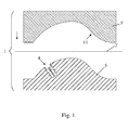
Figure 1 : les deux parties du moule étant écartées (moule ouvert et vide), mise en place de la feuille thermoplastique, préférentiellement préchauffée ; -
Figure 2 : rapprochement des deux parties de moule (préformage de la pièce), puis fermeture étanche du moule et réalisation de l'aspiration pour conformer la pièce par application intime contre la partie de moule supérieure et éventuellement imprimer en relief un motif répétitif (version négative du motif présent sur la surface de la partie de moule supérieure) ; -
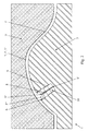
Figure 3 : déplacement en extension du moyen de déformation locale en contact avec la pièce/feuille conformée ; -
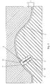
Figure 4 : application de vide au niveau du moyen de déformation locale (préférentiellement après suppression du vide au niveau de la partie de moule supérieure); -
Figure 5 : déplacement en rétractation du moyen de déformation locale dans sa position escamotée (après avoir enlevé le vide ou supprimé l'aspiration au niveau du moyen de déformation) ; -
Figure 6 : ouverture du moule et extraction de la pièce conformée.
-
Figure 1 : the two parts of the mold being spaced apart (open mold and empty), placing the thermoplastic sheet, preferentially preheated; -
Figure 2 : approximation of the two mold parts (preforming of the part), then sealed closure of the mold and realization of the suction to conform the workpiece by intimate application against the upper mold part and possibly print in relief a repetitive pattern (negative version of the pattern on the surface of the upper mold portion); -
Figure 3 : displacement in extension of the local deformation means in contact with the shaped part / sheet; -
Figure 4 : application of vacuum at the local deformation means (preferably after removal of the vacuum at the upper mold portion); -
Figure 5 : retracting displacement of the local deformation means in its retracted position (after removing the vacuum or removing the suction at the deformation means); -
Figure 6 : opening of the mold and extraction of the shaped part.
Les figures des dessins annexés montrent un dispositif de moule de thermoformage pour la réalisation d'une pièce 2 à paroi 2" mince à partir d'une feuille 2 en un matériau thermoplastique.The figures of the accompanying drawings show a thermoforming mold device for producing a
Ce dispositif de moule 1 comprend deux parties de moule 3 et 3' (supérieure et inférieure dans l'exemple représenté) avec des surfaces de travail de formes sensiblement complémentaires et dont l'une des parties au moins est mobile de manière à définir un état d'ouverture et un état de fermeture du moule. De plus, l'une 3' des deux parties de moule 3,3' comporte des moyens d'aspiration pour plaquer la feuille 2 contre sa surface et la cavité 1' formée entre les deux parties de moule 3 et 3' étant sensiblement hermétiquement étanche à l'état de fermeture du moule.This
Pour des raisons de simplification des représentations, les moyens d'étanchéité, d'aspiration sous vide et de déplacement des parties de moule 3,3' ne sont pas représentés sur les figures annexés.For the sake of simplification of the representations, the sealing means, vacuum suction and displacement of the
Conformément à l'invention, l'une 3 au moins des deux parties de moule 3, 3' comporte au moins un moyen 4 de déformation locale d'une feuille 2' présente dans ledit moule 3, 3' à l'état fermé, ledit ou chaque moyen 4 comprenant une pièce 5 de formage en creux avec un bord périphérique 5', pouvant être reliée sélectivement à une source d'aspiration ou de mise en dépression et pouvant être déplacée entre, d'une part, une position repliée, dans laquelle ladite pièce de formage 5 est située au plus en affleurement avec la paroi 2" de la pièce thermoformée 2, voire en retrait ou au plus en affleurement par rapport à la surface de la partie du moule 3 portant ledit moyen de déformation locale 4 et, d'autre part, une position déployée, dans laquelle ladite pièce de formage 5 vient en application sous pression avec son bord périphérique 5' contre la paroi 2" de la pièce thermoformée 2 en appui contre l'autre partie de moule 3'.According to the invention, at least one of the two
L'homme du métier comprend aisément qu'avec les dispositions précédentes, il est possible, avec un même dispositif de moule 1, de réaliser différentes versions d'une même pièce 2, à savoir : sans aucune zone 13 localement déformée, avec une ou certaines zone(s) 13 présente(s), ou encore avec l'ensemble des zones 13 précédentes, lorsqu'une pluralité de moyens 4 sont prévus et qu'aucun, certains ou tous sont utilisés durant la fabrication de la pièce 2 concernée. De plus, ces différentes versions peuvent être fabriquées dans un ordre voulu et choisi (ou imposé par les commandes) sans impacter la productivité, ni le rendement en terme de pièces produites, à l'exception du temps supplémentaire nécessaire pour réaliser la ou les déformations locales additionnelles. Toutefois, une partie au moins de cette durée est en tout état de cause nécessaire pour permettre un refroidissement suffisant de la pièce 2 fraîchement formée dans le moule.The person skilled in the art easily understands that with the preceding arrangements, it is possible, with the
En vue d'éviter toute perte de dépression localement, le bord périphérique 5' est avantageusement pourvu d'un joint de compression 5" permettant de délimiter, lors d'un contact sous pression, une chambre 7 sensiblement étanche avec la paroi 2" de la pièce thermoformée 2.In order to avoid any loss of vacuum locally, the peripheral edge 5 'is advantageously provided with a
Le bord 5' présente en outre un profil (surtout une face interne de profil de bord) adapté à la forme recherchée pour le bord 13' de la zone déformée 13, en particulier au moins légèrement arrondie ou courbe pour éviter la rupture de la feuille 2' et donc de la paroi 2" de la pièce 2. Ainsi, la forme du bord 5' (en fait la conformation du côté intérieur de ce bord) détermine la forme du bord 13' de la zone localement déformée 13 de la pièce 2.The edge 5 'also has a profile (especially an internal edge profile face) adapted to the desired shape for the edge 13' of the
Bien que d'autres constructions puissent être envisagées, il est avantageusement prévu que la pièce de formage en creux 5 soit montée mobile, éventuellement avec guidage en translation dans un logement 8 ménagé dans la partie de moule 3 concernée, ledit guidage étant préférentiellement également assuré en position déployée de ladite pièce de formage 5.Although other constructions can be envisaged, it is advantageously provided that the
En accord avec un mode de réalisation de l'invention, ressortant des
Selon une variante constructive pratique, le déplacement bidirectionnel de la pièce de formage en creux 5 est réalisée par l'intermédiaire d'un vérin 10 pneumatique ou hydraulique, monté et positionné sur ou dans la partie de moule 3 recevant la pièce de formage en creux 5, le guidage en coulissement de ladite pièce 5 étant réalisé par le vérin 10 et/ou par une structure de guidage particulière additionnelle.According to a practical constructive variant, the bidirectional displacement of the
Le mode de réalisation représenté à titre d'exemple sur les figures annexées ne montre qu'un seul moyen 4.The embodiment shown by way of example in the appended figures shows only one means 4.
Néanmoins, en variante, et bien que non représentés, au moins deux moyens de déformation locale 4, montés dans la même partie de moule 3, 3' ou non et activables sélectivement et indépendamment, peuvent être prévus.Nevertheless, alternatively, and although not shown, at least two local deformation means 4, mounted in the
Comme illustré également à titre d'exemple sur les
Pour aboutir à une encore plus grande universalité du dispositif de moule 1, en particularité une plus grande polyvalence en terme de fabrication de versions différentes de la pièce 2, la ou chaque pièce de formage en creux 5 peut être fixée de manière amovible et interchangeable sur l'axe support 9 ou la tige de vérin 10.To achieve an even greater universality of the
L'invention a également pour objet un procédé de fabrication d'une pièce 2 à paroi mince à partir d'une feuille 2' en un matériau thermoplastique, par mise en oeuvre du dispositif 1 de moule décrit précédemment, ladite pièce 2 devant ou non comprendre au moins une zone localisée 13 présentant une configuration particulière.The subject of the invention is also a process for manufacturing a thin-
Ce procédé consiste à mettre en place une feuille 2', éventuellement soumise à un préchauffage, entre les deux parties de moule 3 et 3' à fermer ledit moule pour former une cavité étanche l'entre les deux parties de moule, et éventuellement préformer ladite feuille 2', puis à conformer ladite feuille par déformation plastique par son application intime contre la surface de l'une des parties du moule sous l'effet d'une succion ou d'une aspiration de manière à réaliser la pièce 2, et enfin à ouvrir le moule et à en extraire la pièce thermoformée résultante.This method consists in putting in place a sheet 2 ', optionally subjected to preheating, between the two
Conformément à l'invention, ce procédé consiste en outre, de manière sélective et en fonction de la version de la pièce 2 à obtenir, à réaliser le cas échéant au moins une déformation locale de la feuille 2', après conformation de la feuille 2' par application contre l'une additionnelle des deux parties de moule 3, 3' et alors que cette dernière est dans un état autorisant sa déformation plastique, ladite ou chaque déformation locale 13 étant effectuée par aspiration de la portion de feuille 12 concernée dans une pièce de formage en creux 5, montée dans l'une des deux parties de moule 3, 3', et déplacée en application contre la paroi 2" de la feuille 2'.According to the invention, this method furthermore consists, in a selective manner and as a function of the version of the
Selon une caractéristique avantageuse de l'invention, l'étape de réalisation d'une déformation locale de la feuille 2' consiste à effectuer les opérations suivantes :
- déplacement de la pièce de formage en
creux 5 depuis sa position repliée jusqu'à une position déployée dans laquelle elle vient en appui sous pression contrôlée contre la feuille 2' formant laparoi 2" de lapièce 2 ; - application d'une aspiration ou réalisation d'une dépression dans la pièce de
formage 5 de manière à déformer localement la feuille 2' et à la plaquer intimement contre la surface de la face interne deconformation 5"' de ladite pièce deformage 5 ; - coupure de l'aspiration ou suppression de la dépression ;
- déplacement de la pièce de
formage 5 vers sa position repliée.
- moving the recessed forming
part 5 from its folded position to an extended position in which it bears under controlled pressure against the sheet 2 'forming thewall 2 "of thepart 2; - applying suction or making a depression in the forming
part 5 so as to locally deform the sheet 2 'and to lay it intimately against the surface of the inner face ofconformation 5 "' of said formingpart 5; - cut of aspiration or suppression of depression;
- moving the forming
part 5 to its folded position.
A titre d'exemple, et en particulier lorsque la feuille 2 est constituée d'un matériau du type polyéthylène, polypropylène ou encore polychlorure de vinyl, ladite feuille 2 est préchauffée pour être à une température d'environ 180°C à 210°C durant la phase de formage par aspiration, la phase consécutive optionnelle de déformation locale par l'intermédiaire du moyen 4 étant effectuée lorsque le matériau se trouve encore dans un état déformable plastiquement, à savoir à une température d'environ 150°C à 170°C.By way of example, and particularly when the
Dans un contexte de gestion de production optimisée, le procédé peut consister à produire sélectivement, sur une période de production déterminée, et en fonction d'un programme de fabrication donné résultant par exemple d'un regroupement de commandes clients diversifiées en termes de version de la pièce 1 souhaitée, des pièces 2 comportant ou non une ou plusieurs zone(s) 13 locale(s) à déformation ou configuration particulières.In an optimized production management context, the method can consist in producing selectively, over a given production period, and according to a given manufacturing program resulting for example from a grouping of diversified customer orders in terms of a version of production. the desired
Dans le contexte précité, le procédé peut en outre consister, entre deux cycles ou programmes de fabrication de pièces 2 de versions différentes et devant présenter une ou des zone(s) 13 localement déformée(s) de configuration(s) et d'aspect(s) différents, à interchanger une ou plusieurs pièce(s) de formage en creux 5.In the aforementioned context, the method may further consist, between two cycles or production programs of
Enfin, comme le montre la
En accord avec l'invention, la pièce thermoformée 2 est obtenue par l'intermédiaire du procédé de fabrication décrit précédemment et comporte au moins une déformation en creux 13, formant par exemple un logement pour la réception d'un accessoire, ainsi qu'éventuellement un motif en relief répétitif, présent sur toute la surface de ladite pièce 2.According to the invention, the
Bien entendu, l'invention n'est pas limitée au mode de réalisation décrit et représenté aux dessins annexés. Des modifications restent possibles, notamment du point de vue de la constitution des divers éléments ou par substitution d'équivalents techniques, sans sortir pour autant du domaine de protection de l'invention.Of course, the invention is not limited to the embodiment described and shown in the accompanying drawings. Modifications are possible, particularly from the point of view of the constitution of the various elements or by substitution of technical equivalents, without departing from the scope of protection of the invention.
Claims (13)
procédé caractérisé en ce qu'il consiste en outre, de manière sélective et en fonction de la version de la pièce (2) à obtenir, à réaliser le cas échéant au moins une déformation locale de la feuille (2'), après conformation de la feuille (2') par application contre l'une additionnelle des deux parties de moule (3, 3') et alors que cette dernière est dans un état autorisant sa déformation plastique, ladite ou chaque déformation locale (13) étant effectuée par aspiration de la portion de feuille (12) concernée dans une pièce de formage en creux (5), montée dans l'une des deux parties de moule (3, 3'), et déplacée en application contre la paroi (2") de la feuille (2').A method of manufacturing a thin-walled part from a sheet of thermoplastic material, by use of the mold device according to any one of claims 1 to 8, said part having to comprise at least one zone localized having a particular configuration, said method consisting of placing a sheet, possibly subjected to preheating, between the two mold parts, to close said mold to form a sealed cavity between the two mold parts, and optionally preform said sheet, and to conform said sheet by plastic deformation by its intimate application against the surface of one of the mold parts under the effect of suction or suction to make the part, to open the mold and extract the resulting thermoformed part,
characterized in that it furthermore consists, selectively and as a function of the version of the part (2) to be obtained, of producing, if necessary, at least one local deformation of the sheet (2 '), after conformation of the sheet (2 ') by application against an additional one of the two mold parts (3, 3') and while the latter is in a state allowing its plastic deformation, said or each local deformation (13) being effected by suction of the respective sheet portion (12) in a hollow forming piece (5), mounted in one of the two mold parts (3, 3 '), and moved in application against the wall (2 ") of the sheet (2 ').
Applications Claiming Priority (1)
| Application Number | Priority Date | Filing Date | Title |
|---|---|---|---|
| FR1455347A FR3022176B1 (en) | 2014-06-12 | 2014-06-12 | THERMOFORMING MOLD DEVICE AND METHOD FOR MANUFACTURING THE SAME |
Publications (2)
| Publication Number | Publication Date |
|---|---|
| EP2955000A1 true EP2955000A1 (en) | 2015-12-16 |
| EP2955000B1 EP2955000B1 (en) | 2017-11-22 |
Family
ID=51210674
Family Applications (1)
| Application Number | Title | Priority Date | Filing Date |
|---|---|---|---|
| EP15305881.3A Not-in-force EP2955000B1 (en) | 2014-06-12 | 2015-06-10 | Thermoforming mould device and method for manufacturing same |
Country Status (7)
| Country | Link |
|---|---|
| US (2) | US10000006B2 (en) |
| EP (1) | EP2955000B1 (en) |
| JP (1) | JP6767733B2 (en) |
| CN (1) | CN105172114B (en) |
| ES (1) | ES2659794T3 (en) |
| FR (1) | FR3022176B1 (en) |
| TR (1) | TR201802136T4 (en) |
Families Citing this family (3)
| Publication number | Priority date | Publication date | Assignee | Title |
|---|---|---|---|---|
| US10390912B1 (en) * | 2015-05-04 | 2019-08-27 | Loren S. Adell | Thermoforming aids and methods |
| FR3044953B1 (en) * | 2015-12-10 | 2018-05-18 | Reydel Automotive B.V. | ASPIRATION THERMOFORMING MOLD DEVICE AND METHOD FOR MANUFACTURING THE SAME |
| KR101816789B1 (en) * | 2016-11-29 | 2018-01-15 | (주)동희산업 | Forming apparatus of plastic fuel tank for vehicle |
Citations (6)
| Publication number | Priority date | Publication date | Assignee | Title |
|---|---|---|---|---|
| EP0629485A2 (en) * | 1993-06-16 | 1994-12-21 | SOLVAY (Société Anonyme) | Thermoforming method and mould for forming an article having at least one strongly deformed area |
| JPH09131785A (en) * | 1995-11-10 | 1997-05-20 | Honda Motor Co Ltd | Vacuum forming method |
| EP1110699A1 (en) * | 1999-12-15 | 2001-06-27 | S.A.R.L. Polymat | Thermoforming press for deforming of carpets especially floor carpets for automobiles |
| WO2007101868A2 (en) * | 2006-03-08 | 2007-09-13 | Recticel Automobilsysteme Gmbh | Process for the production of a three-dimensionally shaped sandwich structure |
| FR2900862A1 (en) | 2006-03-15 | 2007-11-16 | Visteon Global Tech Inc | METHOD FOR FORMING A MULTI-COMPONENT COATING FOR A DASHBOARD ASSEMBLY |
| US20130221698A1 (en) | 2010-04-20 | 2013-08-29 | Faurecia Interior Systems, Inc. | Negative thermoforming process for vehicle interior coverings |
Family Cites Families (10)
| Publication number | Priority date | Publication date | Assignee | Title |
|---|---|---|---|---|
| JPS6127235A (en) * | 1984-07-19 | 1986-02-06 | Matsushita Electric Works Ltd | Method of molding thermoplastic resin |
| GB2220879B (en) * | 1988-06-24 | 1992-11-18 | Polistock Nv | A method of producing laminated panels |
| JP3370172B2 (en) * | 1994-02-10 | 2003-01-27 | 三井屋工業株式会社 | Vacuum forming apparatus and vacuum forming method |
| JP3901901B2 (en) * | 2000-01-05 | 2007-04-04 | カルソニックカンセイ株式会社 | Skin shaping method and apparatus for vehicle interior panel |
| JP4110770B2 (en) * | 2001-06-15 | 2008-07-02 | トヨタ紡織株式会社 | Board product molding method and molding apparatus used therefor |
| JP4062025B2 (en) * | 2002-09-13 | 2008-03-19 | 豊田合成株式会社 | Vacuum suction heat processing method for automobile interior parts |
| FR2883795B1 (en) * | 2005-03-31 | 2010-01-15 | Stephane Sorlin | IMPROVEMENT OF THE PRESSES OF FACTORING, IN PARTICULAR PRESSES OF PERMANENT EMBOSSING |
| EP2229489B1 (en) * | 2007-11-26 | 2018-07-04 | Johnson Controls Technology Company | Method for forming a vehicle trim panel |
| JP5730594B2 (en) * | 2011-01-28 | 2015-06-10 | カルソニックカンセイ株式会社 | Vacuum forming method |
| FR3044953B1 (en) * | 2015-12-10 | 2018-05-18 | Reydel Automotive B.V. | ASPIRATION THERMOFORMING MOLD DEVICE AND METHOD FOR MANUFACTURING THE SAME |
-
2014
- 2014-06-12 FR FR1455347A patent/FR3022176B1/en not_active Expired - Fee Related
-
2015
- 2015-06-09 US US14/734,322 patent/US10000006B2/en not_active Expired - Fee Related
- 2015-06-10 EP EP15305881.3A patent/EP2955000B1/en not_active Not-in-force
- 2015-06-10 ES ES15305881.3T patent/ES2659794T3/en active Active
- 2015-06-10 TR TR2018/02136T patent/TR201802136T4/en unknown
- 2015-06-12 JP JP2015119471A patent/JP6767733B2/en not_active Expired - Fee Related
- 2015-06-12 CN CN201510324503.9A patent/CN105172114B/en not_active Expired - Fee Related
-
2018
- 2018-05-21 US US15/985,309 patent/US11020893B2/en active Active
Patent Citations (6)
| Publication number | Priority date | Publication date | Assignee | Title |
|---|---|---|---|---|
| EP0629485A2 (en) * | 1993-06-16 | 1994-12-21 | SOLVAY (Société Anonyme) | Thermoforming method and mould for forming an article having at least one strongly deformed area |
| JPH09131785A (en) * | 1995-11-10 | 1997-05-20 | Honda Motor Co Ltd | Vacuum forming method |
| EP1110699A1 (en) * | 1999-12-15 | 2001-06-27 | S.A.R.L. Polymat | Thermoforming press for deforming of carpets especially floor carpets for automobiles |
| WO2007101868A2 (en) * | 2006-03-08 | 2007-09-13 | Recticel Automobilsysteme Gmbh | Process for the production of a three-dimensionally shaped sandwich structure |
| FR2900862A1 (en) | 2006-03-15 | 2007-11-16 | Visteon Global Tech Inc | METHOD FOR FORMING A MULTI-COMPONENT COATING FOR A DASHBOARD ASSEMBLY |
| US20130221698A1 (en) | 2010-04-20 | 2013-08-29 | Faurecia Interior Systems, Inc. | Negative thermoforming process for vehicle interior coverings |
Non-Patent Citations (1)
| Title |
|---|
| DATABASE WPI Week 199730, Derwent World Patents Index; AN 1997-327806, XP002728859 * |
Also Published As
| Publication number | Publication date |
|---|---|
| FR3022176B1 (en) | 2017-01-20 |
| TR201802136T4 (en) | 2018-03-21 |
| FR3022176A1 (en) | 2015-12-18 |
| US10000006B2 (en) | 2018-06-19 |
| CN105172114B (en) | 2019-04-16 |
| EP2955000B1 (en) | 2017-11-22 |
| JP2016026921A (en) | 2016-02-18 |
| US11020893B2 (en) | 2021-06-01 |
| US20180264709A1 (en) | 2018-09-20 |
| CN105172114A (en) | 2015-12-23 |
| ES2659794T3 (en) | 2018-03-19 |
| JP6767733B2 (en) | 2020-10-14 |
| US20150360411A1 (en) | 2015-12-17 |
Similar Documents
| Publication | Publication Date | Title |
|---|---|---|
| EP3178631B1 (en) | Suction thermoforming mould device, manufacturing method implementing same and manufactured element | |
| EP1136239B1 (en) | Method for producing a reinforced thermoplastic part and mould | |
| EP2955000B1 (en) | Thermoforming mould device and method for manufacturing same | |
| EP3575056B1 (en) | Method for manufacturing a guiding rod for a pump | |
| FR2921581A1 (en) | METHOD AND TOOLS FOR MANUFACTURING A COMPOSITE PIECE, COMPOSITE CAP OBTAINED BY SUCH A METHOD OR TO SUCH TOOLS | |
| FR3008918A1 (en) | METHOD FOR MANUFACTURING INTERIOR CLAD PART AND CORRESPONDING PIECE | |
| EP1523404B1 (en) | Device and method for thermoforming an object having a back draft portion | |
| FR2998502A1 (en) | PROCESS FOR MANUFACTURING THERMOPLASTIC MATERIAL PARTS AND CORRESPONDING MOLD DEVICE | |
| CH375138A (en) | Process for manufacturing thin-walled thermoformable plastic containers and installation for its implementation | |
| FR2947475A1 (en) | PISTON FOR POSITIONING A FOOD POT DECORATION IN A MOLD, DEVICE AND METHOD THEREOF | |
| FR3056139B1 (en) | SYSTEM FOR MAKING A GARMENT COMPONENT COMPRISING A HOLDING ELEMENT | |
| FR3081747A1 (en) | MOLDING TOOL WITH COMPRESSED GAS-OPERATED HOLDER | |
| EP3116669B1 (en) | Die with ejector for stamped piece with a gutter at the edge | |
| FR2880834A1 (en) | Objects thermoforming device comprises a mould with chamber and outside the mould having a piston, which penetrates into the chamber by an opening to push back a thermoplastic material into the chamber | |
| EP0433203B1 (en) | Method and apparatus for drawing conical containers and containers so obtained | |
| WO2009071808A1 (en) | Method of manufacturing a motor vehicle equipment part and corresponding equipment part | |
| FR3038248A1 (en) | METHOD AND DEVICE FOR MANUFACTURING A HYBRID OR COMPOSITE PART BASED ON THERMOPLASTIC MATERIAL HAVING A FACE OF APPEARANCE AND A TECHNICAL FACE | |
| EP0707533B1 (en) | Method for the manufacture of a multilayered object by moulding and mould for the manufacture of such an object | |
| FR3124756A1 (en) | Process for manufacturing a double-decorated trim element and associated device | |
| FR2482003A1 (en) | METHOD FOR PRODUCING A CLOSING DEVICE AND DEVICE FOR IMPLEMENTING THE METHOD | |
| FR3096291A1 (en) | Manufacturing process of a three-dimensional composite part and part obtained | |
| FR3020618A1 (en) | METHOD FOR MANUFACTURING A FILLING ELEMENT AND CORRESPONDING MANUFACTURING ASSEMBLY | |
| FR2899512A1 (en) | Device for cutting injection core from plastics injection molding, e.g. vehicle bodywork strip, comprises injection shoe actuated to move translationally and section core before demolding | |
| FR2876620A1 (en) | Device for designing sidewall of pot by plastic band thermoforming comprises moveable mould with a punch to push the band, chamber having slot to introduce design and moveable sliding sleeve piston to push the design into the annular space | |
| FR2952598A1 (en) | Trim element i.e. inner trim element, fabricating method for e.g. fascia of motor vehicle, involves obtaining skin, and fixing back element on inner surface around through-hole to close through-hole without extending beyond outer surface |
Legal Events
| Date | Code | Title | Description |
|---|---|---|---|
| PUAI | Public reference made under article 153(3) epc to a published international application that has entered the european phase |
Free format text: ORIGINAL CODE: 0009012 |
|
| AK | Designated contracting states |
Kind code of ref document: A1 Designated state(s): AL AT BE BG CH CY CZ DE DK EE ES FI FR GB GR HR HU IE IS IT LI LT LU LV MC MK MT NL NO PL PT RO RS SE SI SK SM TR |
|
| AX | Request for extension of the european patent |
Extension state: BA ME |
|
| 17P | Request for examination filed |
Effective date: 20160615 |
|
| RBV | Designated contracting states (corrected) |
Designated state(s): AL AT BE BG CH CY CZ DE DK EE ES FI FR GB GR HR HU IE IS IT LI LT LU LV MC MK MT NL NO PL PT RO RS SE SI SK SM TR |
|
| RIC1 | Information provided on ipc code assigned before grant |
Ipc: B29C 51/10 20060101ALN20170518BHEP Ipc: B29C 51/36 20060101ALN20170518BHEP Ipc: B29C 51/08 20060101AFI20170518BHEP Ipc: B29L 31/30 20060101ALN20170518BHEP |
|
| GRAP | Despatch of communication of intention to grant a patent |
Free format text: ORIGINAL CODE: EPIDOSNIGR1 |
|
| RIC1 | Information provided on ipc code assigned before grant |
Ipc: B29C 51/36 20060101ALN20170606BHEP Ipc: B29C 51/10 20060101ALN20170606BHEP Ipc: B29L 31/30 20060101ALN20170606BHEP Ipc: B29C 51/08 20060101AFI20170606BHEP |
|
| INTG | Intention to grant announced |
Effective date: 20170711 |
|
| GRAS | Grant fee paid |
Free format text: ORIGINAL CODE: EPIDOSNIGR3 |
|
| GRAA | (expected) grant |
Free format text: ORIGINAL CODE: 0009210 |
|
| AK | Designated contracting states |
Kind code of ref document: B1 Designated state(s): AL AT BE BG CH CY CZ DE DK EE ES FI FR GB GR HR HU IE IS IT LI LT LU LV MC MK MT NL NO PL PT RO RS SE SI SK SM TR |
|
| REG | Reference to a national code |
Ref country code: GB Ref legal event code: FG4D Free format text: NOT ENGLISH |
|
| REG | Reference to a national code |
Ref country code: CH Ref legal event code: EP |
|
| REG | Reference to a national code |
Ref country code: IE Ref legal event code: FG4D Free format text: LANGUAGE OF EP DOCUMENT: FRENCH |
|
| REG | Reference to a national code |
Ref country code: AT Ref legal event code: REF Ref document number: 947999 Country of ref document: AT Kind code of ref document: T Effective date: 20171215 |
|
| REG | Reference to a national code |
Ref country code: DE Ref legal event code: R096 Ref document number: 602015006178 Country of ref document: DE |
|
| REG | Reference to a national code |
Ref country code: ES Ref legal event code: FG2A Ref document number: 2659794 Country of ref document: ES Kind code of ref document: T3 Effective date: 20180319 |
|
| REG | Reference to a national code |
Ref country code: NL Ref legal event code: MP Effective date: 20171122 |
|
| REG | Reference to a national code |
Ref country code: LT Ref legal event code: MG4D |
|
| REG | Reference to a national code |
Ref country code: AT Ref legal event code: MK05 Ref document number: 947999 Country of ref document: AT Kind code of ref document: T Effective date: 20171122 |
|
| PG25 | Lapsed in a contracting state [announced via postgrant information from national office to epo] |
Ref country code: LT Free format text: LAPSE BECAUSE OF FAILURE TO SUBMIT A TRANSLATION OF THE DESCRIPTION OR TO PAY THE FEE WITHIN THE PRESCRIBED TIME-LIMIT Effective date: 20171122 Ref country code: NL Free format text: LAPSE BECAUSE OF FAILURE TO SUBMIT A TRANSLATION OF THE DESCRIPTION OR TO PAY THE FEE WITHIN THE PRESCRIBED TIME-LIMIT Effective date: 20171122 Ref country code: FI Free format text: LAPSE BECAUSE OF FAILURE TO SUBMIT A TRANSLATION OF THE DESCRIPTION OR TO PAY THE FEE WITHIN THE PRESCRIBED TIME-LIMIT Effective date: 20171122 Ref country code: SE Free format text: LAPSE BECAUSE OF FAILURE TO SUBMIT A TRANSLATION OF THE DESCRIPTION OR TO PAY THE FEE WITHIN THE PRESCRIBED TIME-LIMIT Effective date: 20171122 Ref country code: NO Free format text: LAPSE BECAUSE OF FAILURE TO SUBMIT A TRANSLATION OF THE DESCRIPTION OR TO PAY THE FEE WITHIN THE PRESCRIBED TIME-LIMIT Effective date: 20180222 |
|
| PG25 | Lapsed in a contracting state [announced via postgrant information from national office to epo] |
Ref country code: RS Free format text: LAPSE BECAUSE OF FAILURE TO SUBMIT A TRANSLATION OF THE DESCRIPTION OR TO PAY THE FEE WITHIN THE PRESCRIBED TIME-LIMIT Effective date: 20171122 Ref country code: GR Free format text: LAPSE BECAUSE OF FAILURE TO SUBMIT A TRANSLATION OF THE DESCRIPTION OR TO PAY THE FEE WITHIN THE PRESCRIBED TIME-LIMIT Effective date: 20180223 Ref country code: LV Free format text: LAPSE BECAUSE OF FAILURE TO SUBMIT A TRANSLATION OF THE DESCRIPTION OR TO PAY THE FEE WITHIN THE PRESCRIBED TIME-LIMIT Effective date: 20171122 Ref country code: AT Free format text: LAPSE BECAUSE OF FAILURE TO SUBMIT A TRANSLATION OF THE DESCRIPTION OR TO PAY THE FEE WITHIN THE PRESCRIBED TIME-LIMIT Effective date: 20171122 Ref country code: HR Free format text: LAPSE BECAUSE OF FAILURE TO SUBMIT A TRANSLATION OF THE DESCRIPTION OR TO PAY THE FEE WITHIN THE PRESCRIBED TIME-LIMIT Effective date: 20171122 Ref country code: BG Free format text: LAPSE BECAUSE OF FAILURE TO SUBMIT A TRANSLATION OF THE DESCRIPTION OR TO PAY THE FEE WITHIN THE PRESCRIBED TIME-LIMIT Effective date: 20180222 |
|
| REG | Reference to a national code |
Ref country code: SK Ref legal event code: T3 Ref document number: E 26489 Country of ref document: SK |
|
| REG | Reference to a national code |
Ref country code: FR Ref legal event code: PLFP Year of fee payment: 4 |
|
| PG25 | Lapsed in a contracting state [announced via postgrant information from national office to epo] |
Ref country code: DK Free format text: LAPSE BECAUSE OF FAILURE TO SUBMIT A TRANSLATION OF THE DESCRIPTION OR TO PAY THE FEE WITHIN THE PRESCRIBED TIME-LIMIT Effective date: 20171122 Ref country code: EE Free format text: LAPSE BECAUSE OF FAILURE TO SUBMIT A TRANSLATION OF THE DESCRIPTION OR TO PAY THE FEE WITHIN THE PRESCRIBED TIME-LIMIT Effective date: 20171122 Ref country code: CY Free format text: LAPSE BECAUSE OF FAILURE TO SUBMIT A TRANSLATION OF THE DESCRIPTION OR TO PAY THE FEE WITHIN THE PRESCRIBED TIME-LIMIT Effective date: 20171122 Ref country code: CZ Free format text: LAPSE BECAUSE OF FAILURE TO SUBMIT A TRANSLATION OF THE DESCRIPTION OR TO PAY THE FEE WITHIN THE PRESCRIBED TIME-LIMIT Effective date: 20171122 |
|
| REG | Reference to a national code |
Ref country code: DE Ref legal event code: R097 Ref document number: 602015006178 Country of ref document: DE |
|
| PG25 | Lapsed in a contracting state [announced via postgrant information from national office to epo] |
Ref country code: IT Free format text: LAPSE BECAUSE OF FAILURE TO SUBMIT A TRANSLATION OF THE DESCRIPTION OR TO PAY THE FEE WITHIN THE PRESCRIBED TIME-LIMIT Effective date: 20171122 Ref country code: PL Free format text: LAPSE BECAUSE OF FAILURE TO SUBMIT A TRANSLATION OF THE DESCRIPTION OR TO PAY THE FEE WITHIN THE PRESCRIBED TIME-LIMIT Effective date: 20171122 Ref country code: SM Free format text: LAPSE BECAUSE OF FAILURE TO SUBMIT A TRANSLATION OF THE DESCRIPTION OR TO PAY THE FEE WITHIN THE PRESCRIBED TIME-LIMIT Effective date: 20171122 Ref country code: RO Free format text: LAPSE BECAUSE OF FAILURE TO SUBMIT A TRANSLATION OF THE DESCRIPTION OR TO PAY THE FEE WITHIN THE PRESCRIBED TIME-LIMIT Effective date: 20171122 |
|
| PG25 | Lapsed in a contracting state [announced via postgrant information from national office to epo] |
Ref country code: MT Free format text: LAPSE BECAUSE OF FAILURE TO SUBMIT A TRANSLATION OF THE DESCRIPTION OR TO PAY THE FEE WITHIN THE PRESCRIBED TIME-LIMIT Effective date: 20171122 |
|
| PLBE | No opposition filed within time limit |
Free format text: ORIGINAL CODE: 0009261 |
|
| STAA | Information on the status of an ep patent application or granted ep patent |
Free format text: STATUS: NO OPPOSITION FILED WITHIN TIME LIMIT |
|
| 26N | No opposition filed |
Effective date: 20180823 |
|
| PG25 | Lapsed in a contracting state [announced via postgrant information from national office to epo] |
Ref country code: SI Free format text: LAPSE BECAUSE OF FAILURE TO SUBMIT A TRANSLATION OF THE DESCRIPTION OR TO PAY THE FEE WITHIN THE PRESCRIBED TIME-LIMIT Effective date: 20171122 |
|
| REG | Reference to a national code |
Ref country code: CH Ref legal event code: PL |
|
| REG | Reference to a national code |
Ref country code: BE Ref legal event code: MM Effective date: 20180630 |
|
| REG | Reference to a national code |
Ref country code: IE Ref legal event code: MM4A |
|
| PG25 | Lapsed in a contracting state [announced via postgrant information from national office to epo] |
Ref country code: LU Free format text: LAPSE BECAUSE OF NON-PAYMENT OF DUE FEES Effective date: 20180610 Ref country code: MC Free format text: LAPSE BECAUSE OF FAILURE TO SUBMIT A TRANSLATION OF THE DESCRIPTION OR TO PAY THE FEE WITHIN THE PRESCRIBED TIME-LIMIT Effective date: 20171122 |
|
| PG25 | Lapsed in a contracting state [announced via postgrant information from national office to epo] |
Ref country code: LI Free format text: LAPSE BECAUSE OF NON-PAYMENT OF DUE FEES Effective date: 20180630 Ref country code: IE Free format text: LAPSE BECAUSE OF NON-PAYMENT OF DUE FEES Effective date: 20180610 Ref country code: CH Free format text: LAPSE BECAUSE OF NON-PAYMENT OF DUE FEES Effective date: 20180630 |
|
| PG25 | Lapsed in a contracting state [announced via postgrant information from national office to epo] |
Ref country code: BE Free format text: LAPSE BECAUSE OF NON-PAYMENT OF DUE FEES Effective date: 20180630 |
|
| PGFP | Annual fee paid to national office [announced via postgrant information from national office to epo] |
Ref country code: DE Payment date: 20190423 Year of fee payment: 14 |
|
| GBPC | Gb: european patent ceased through non-payment of renewal fee |
Effective date: 20190610 |
|
| PG25 | Lapsed in a contracting state [announced via postgrant information from national office to epo] |
Ref country code: GB Free format text: LAPSE BECAUSE OF NON-PAYMENT OF DUE FEES Effective date: 20190610 |
|
| PG25 | Lapsed in a contracting state [announced via postgrant information from national office to epo] |
Ref country code: PT Free format text: LAPSE BECAUSE OF FAILURE TO SUBMIT A TRANSLATION OF THE DESCRIPTION OR TO PAY THE FEE WITHIN THE PRESCRIBED TIME-LIMIT Effective date: 20171122 |
|
| PG25 | Lapsed in a contracting state [announced via postgrant information from national office to epo] |
Ref country code: HU Free format text: LAPSE BECAUSE OF FAILURE TO SUBMIT A TRANSLATION OF THE DESCRIPTION OR TO PAY THE FEE WITHIN THE PRESCRIBED TIME-LIMIT; INVALID AB INITIO Effective date: 20150610 Ref country code: MK Free format text: LAPSE BECAUSE OF NON-PAYMENT OF DUE FEES Effective date: 20171122 |
|
| PG25 | Lapsed in a contracting state [announced via postgrant information from national office to epo] |
Ref country code: AL Free format text: LAPSE BECAUSE OF FAILURE TO SUBMIT A TRANSLATION OF THE DESCRIPTION OR TO PAY THE FEE WITHIN THE PRESCRIBED TIME-LIMIT Effective date: 20171122 Ref country code: IS Free format text: LAPSE BECAUSE OF FAILURE TO SUBMIT A TRANSLATION OF THE DESCRIPTION OR TO PAY THE FEE WITHIN THE PRESCRIBED TIME-LIMIT Effective date: 20180322 |
|
| PGFP | Annual fee paid to national office [announced via postgrant information from national office to epo] |
Ref country code: SK Payment date: 20200608 Year of fee payment: 6 |
|
| REG | Reference to a national code |
Ref country code: ES Ref legal event code: PC2A Owner name: SMRC AUTOMOTIVE HOLDINGS NETHERLANDS B.V Effective date: 20210903 |
|
| REG | Reference to a national code |
Ref country code: DE Ref legal event code: R081 Ref document number: 602015006178 Country of ref document: DE Owner name: SMRC AUTOMOTIVE HOLDINGS NETHERLANDS B.V., NL Free format text: FORMER OWNER: REYDEL AUTOMOTIVE B.V., BAARN, NL |
|
| REG | Reference to a national code |
Ref country code: SK Ref legal event code: MM4A Ref document number: E 26489 Country of ref document: SK Effective date: 20210610 |
|
| PG25 | Lapsed in a contracting state [announced via postgrant information from national office to epo] |
Ref country code: SK Free format text: LAPSE BECAUSE OF NON-PAYMENT OF DUE FEES Effective date: 20210610 |
|
| PG25 | Lapsed in a contracting state [announced via postgrant information from national office to epo] |
Ref country code: TR Free format text: LAPSE BECAUSE OF NON-PAYMENT OF DUE FEES Effective date: 20200610 |
|
| PGFP | Annual fee paid to national office [announced via postgrant information from national office to epo] |
Ref country code: FR Payment date: 20220628 Year of fee payment: 8 |
|
| PGFP | Annual fee paid to national office [announced via postgrant information from national office to epo] |
Ref country code: ES Payment date: 20220829 Year of fee payment: 8 |
|
| REG | Reference to a national code |
Ref country code: DE Ref legal event code: R119 Ref document number: 602015006178 Country of ref document: DE |
|
| PG25 | Lapsed in a contracting state [announced via postgrant information from national office to epo] |
Ref country code: DE Free format text: LAPSE BECAUSE OF NON-PAYMENT OF DUE FEES Effective date: 20240103 |
|
| PG25 | Lapsed in a contracting state [announced via postgrant information from national office to epo] |
Ref country code: FR Free format text: LAPSE BECAUSE OF NON-PAYMENT OF DUE FEES Effective date: 20230630 |
|
| REG | Reference to a national code |
Ref country code: ES Ref legal event code: FD2A Effective date: 20240731 |