EP0803291A2 - Buse pour tuyau d'arrosage - Google Patents
Buse pour tuyau d'arrosage Download PDFInfo
- Publication number
- EP0803291A2 EP0803291A2 EP97100524A EP97100524A EP0803291A2 EP 0803291 A2 EP0803291 A2 EP 0803291A2 EP 97100524 A EP97100524 A EP 97100524A EP 97100524 A EP97100524 A EP 97100524A EP 0803291 A2 EP0803291 A2 EP 0803291A2
- Authority
- EP
- European Patent Office
- Prior art keywords
- hose nozzle
- nozzle according
- water
- piston
- chamber
- Prior art date
- Legal status (The legal status is an assumption and is not a legal conclusion. Google has not performed a legal analysis and makes no representation as to the accuracy of the status listed.)
- Withdrawn
Links
Images


Classifications
-
- B—PERFORMING OPERATIONS; TRANSPORTING
- B05—SPRAYING OR ATOMISING IN GENERAL; APPLYING FLUENT MATERIALS TO SURFACES, IN GENERAL
- B05B—SPRAYING APPARATUS; ATOMISING APPARATUS; NOZZLES
- B05B1/00—Nozzles, spray heads or other outlets, with or without auxiliary devices such as valves, heating means
- B05B1/14—Nozzles, spray heads or other outlets, with or without auxiliary devices such as valves, heating means with multiple outlet openings; with strainers in or outside the outlet opening
- B05B1/16—Nozzles, spray heads or other outlets, with or without auxiliary devices such as valves, heating means with multiple outlet openings; with strainers in or outside the outlet opening having selectively- effective outlets
- B05B1/1609—Nozzles, spray heads or other outlets, with or without auxiliary devices such as valves, heating means with multiple outlet openings; with strainers in or outside the outlet opening having selectively- effective outlets with a selecting mechanism comprising a lift valve
-
- B—PERFORMING OPERATIONS; TRANSPORTING
- B05—SPRAYING OR ATOMISING IN GENERAL; APPLYING FLUENT MATERIALS TO SURFACES, IN GENERAL
- B05B—SPRAYING APPARATUS; ATOMISING APPARATUS; NOZZLES
- B05B1/00—Nozzles, spray heads or other outlets, with or without auxiliary devices such as valves, heating means
- B05B1/30—Nozzles, spray heads or other outlets, with or without auxiliary devices such as valves, heating means designed to control volume of flow, e.g. with adjustable passages
- B05B1/3013—Lift valves
-
- B—PERFORMING OPERATIONS; TRANSPORTING
- B05—SPRAYING OR ATOMISING IN GENERAL; APPLYING FLUENT MATERIALS TO SURFACES, IN GENERAL
- B05B—SPRAYING APPARATUS; ATOMISING APPARATUS; NOZZLES
- B05B1/00—Nozzles, spray heads or other outlets, with or without auxiliary devices such as valves, heating means
- B05B1/14—Nozzles, spray heads or other outlets, with or without auxiliary devices such as valves, heating means with multiple outlet openings; with strainers in or outside the outlet opening
- B05B1/18—Roses; Shower heads
-
- B—PERFORMING OPERATIONS; TRANSPORTING
- B05—SPRAYING OR ATOMISING IN GENERAL; APPLYING FLUENT MATERIALS TO SURFACES, IN GENERAL
- B05B—SPRAYING APPARATUS; ATOMISING APPARATUS; NOZZLES
- B05B15/00—Details of spraying plant or spraying apparatus not otherwise provided for; Accessories
- B05B15/60—Arrangements for mounting, supporting or holding spraying apparatus
- B05B15/62—Arrangements for supporting spraying apparatus, e.g. suction cups
-
- B—PERFORMING OPERATIONS; TRANSPORTING
- B05—SPRAYING OR ATOMISING IN GENERAL; APPLYING FLUENT MATERIALS TO SURFACES, IN GENERAL
- B05B—SPRAYING APPARATUS; ATOMISING APPARATUS; NOZZLES
- B05B15/00—Details of spraying plant or spraying apparatus not otherwise provided for; Accessories
- B05B15/60—Arrangements for mounting, supporting or holding spraying apparatus
- B05B15/63—Handgrips
Definitions
- the present invention is in the field of irrigation equipment and more specifically it is concerned with a nozzle of the type typically attached at a free end of a flexible hose.
- Pistol nozzles, hose nozzles and spray nozzles are collectively referred to as "hose nozzles" .
- Hose nozzles of the specified type have long been known and are used for mounting on a free end of a garden hose for the purpose of emitting a water jet or spray at a desired discharge rate and at a suitable pattern. It may, for example, be required to use a sharp and strong water jet for rinsing a concrete or paved surface, or to use a gentle shower for irrigating a flower bed or a fan-like shaped spray for irrigating a lawn or a powerful wide jet which may be used for distant irrigation.
- the so called “pistol” or “spray” nozzles typically comprise a body having a shape resembling that of a pistol and comprising a water inlet connected to a hose, a water outlet and an activator, usually being in the form of a lever or a trigger.
- the water outlet comprises a rotatable head comprising several discharge patterns which may be rotated so that a desired pattern faces the water outlet.
- hose nozzles require manually retaining of the activator for controlling the water discharge rate, and they usually employ a biasing spring against which force should be constantly applied.
- a locking member e.g. in the form of a ratchet mechanism or an adjustable screw, however such means require using both hands of the operator for locking or releasing.
- only one pattern may be used at a time, and again, two hands are required for changing positions of the head to obtain a different irrigation pattern.
- a hose nozzle comprising a housing with a water inlet and at least one water outlet and a water duct intermediate said water inlet and each of said at least one water outlet; a flow regulator associated with each water outlet and being operable between a closed position in which Water flow is prohibited and an open position in which water flow is admitted; each flow regulator being provided with an adjustable activator on a surface of the housing.
- the flow regulator consists of a first chamber in flow communication with a water inlet side of the water duct and a second chamber in flow communication with the water outlet side of the water duct, with a sealing port intermediate said chambers; and a piston being displaceable between a closed position in which water flow between the chambers is prohibited and an open position in which water flow between the chambers is admitted.
- the piston of the flow regulator comprises a portion projecting through an opening in one of the chambers and being engageable with the adjustable activator.
- the sealing port between the chambers is a necking portion and preferably the sealing port is encircled by a resilient seal.
- the adjustable activator is a slide accommodated in the housing and engageable with the piston for transmitting axial displacement to the piston upon displacement of the slide between a first and a second position and wherein the adjustable activator may be retained at any position.
- one of a portion of the slide and a portion of the housing opposite the respective portion of the slide comprises a serrated surface and the other of the portion of the slide and the portion of the housing comprises a matching projecting tooth or toothed surface for releasable engagement with the serrated surface, whereby the slide may be releasably retained at any location between the first and second positions thereof.
- the slide In order to impart axial displacement to the piston, the slide has an inclined path adapted for engaging the projecting portion of the piston, depending on the relative position of the inclined path with respect to the piston.
- the piston is supported in the chamber by a resilient gasket biasing the piston to its open position and sealing the opening of that chamber.
- the arrangement is such the resilient gasket operates as a dynamic sealing member wherein biasing of the piston and sealing of the chamber are improved by aid of water applying pressure on the gasket.
- the second chamber is positioned essentially above the first chamber and wherein the piston is supported in the second chamber and projects from a top wall of the second chamber, said resilient gasket also serving for sealing the opening in the chamber through which the piston projects.
- the hose nozzle comprises a single water outlet with an adjustable spout mounted thereon for adjusting the discharge rate and pattern of the water emitted.
- the hose nozzle comprises at least two water outlets, each having a spout for emitting water at a different pattern, e.g. a gentle shower, a sharp jet, a wide stream, etc.
- all the first chambers are in flow communication with one another and a common resilient seal is provided between the first and second chambers of the adjacent flow regulators.
- the embodiment comprising more than one water outlet, it is possible to have more than one flow regulator in an open position, simultaneously, whereby it is possible to obtain combined water patterns and at varying ranges, e.g. a shower for irrigating at the short distance and a jet for irrigating at a larger range, etc.
- the spouts of the water outlets are replaceable and the water inlet end of the duct comprises a hose connector, as known per se .
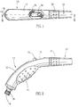
- FIGs. 1 to 3 of the drawings directed to a first embodiment of the invention which is a single outlet hose nozzle.
- An ergonomically designed housing generally designated 10 has a gripping portion 12 with a bulged surface 14 for improved gripping.
- the housing 10 further comprises an inlet 16 for water ingress, provided with a standard hose snap-type connector 18 connected to a duct generally designated 20 and being supported within the housing 10 .
- the duct 20 is divided by a flow regulator generally designated 22 into an inlet portion 24 and an outlet portion 26 , the later having an outle t 28 screw fitted with an adjustable spout 30 , whereby rotating a grip ring 32 brings about changing the cross-sectional area of the discharge nozzle 34 for controlling the water discharge pattern, as known per se .
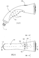
- the flow regulator 22 consists of a bottom chamber 40 being in flow communication with the inlet portion 24 of the duct 20 and a top chamber 42 above the bottom chamber 40 and being in flow communication with the outlet portion 26 of the duct 20 .
- a necking sealing port 44 and a resilient seal 46 having an eight-like shape as seen in Fig. 4, encircling both the sealing port 44 and the passage 48 between the bottom chamber 40 and the inlet portion 24 of the duct 20 .
- a piston 50 is mounted in the top chamber 42 having at a bottom end thereof a sealing ring 52 suitable for sealing engagement with the sealing port 44 as will hereinafter be explained, and a stem 54 projecting through an opening 56 in the top chamber 42 .
- the piston 50 is supported in the top chamber by a resilient gasket 60 which serves also for biasing the piston into its uppermost position, as seen in Fig. 3.
- An activating slide 76 is supported in the housing by suitable grooves (not seen) and adapted for sliding within the housing 10 having a knob 78 projecting through a slot 80 in the housing 10 .
- a bottom face of the activator 76 has an inclined ramp 82 slidingly engaging the top end of the stem 54 of the piston 50 .
- a ridged projection 86 is provided on bed 88 integral with the outlet portion 26 , slidingly supporting the activating slide 76 , the ridged projection 86 adapted for snapping engaging with any of a plurality of recesses 90 provided at the front of the activating slide on a bottom face, for arresting the slide.
- the arrangement is such that displacing the activating slide 76 by sliding the projecting knob 78 rearwardly, entails gradual axial displacement of the piston 50 downward, whereby the cross-sectional area of the sealing port 44 decreases or entirely closes, whereby water flow between the chambers is prohibited.
- the activating slide may be set at any intermediate position resulting in change of the water discharge. Changing position of the slide is by applying gentle pressure on the know 78 for releasing the ridged projection 86 and sliding the activator within the slot 80 .
- the construction of the resilient gasket 60 is such that it serves as a dynamic seal, whereby pressure applied by the water on the bottom surface of the gasket 60 tensions the gasket and thus improves the sealing of the opening 56 and assists in the upward biasing of the piston 50 .
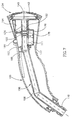
- the hose nozzle has a housing 100 with an ergonomic design and comprises a gripping portion 102 with a plurality of bulges 104 .
- the hose nozzle further comprises a duct generally referred to at 106 having an inlet portion 108 with a hose connector 110 at its rear end.
- the inlet portion 108 of the duct 106 leads to a bottom chamber 111 of three flow regulators generally designated at 112 , the bottom chamber is provided with three compartments 114, 116 and 118 (seen in Fig. 8), all three compartments being in flow communication with one another.
- Top chambers 120, 122 and 124 are located above each respective bottom compartment of the bottom chamber 111 , each top chamber being associated with an outlet portion 126, 128 and 130 respectively, as seen in Fig. 9.
- a distribution head 134 is secured to the front end of the housing 100 having an opening opposite each of the outlet portions 126 , 128 and 130 .
- a first opening 136 leads to a wide stream spout 138
- a second opening 140 opposite outlet 128 leads to a gentle shower discharge grid plate 142
- a third opening 144 (see Fig. 9) opposite outlet 130 leads to a narrow jet stream spout 146 .
- each of the top chambers 120, 122 and 124 of the flow regulators 112 accommodates a piston 150, 152 and 156 respectively, each of the pistons being supported by a resilient gasket 158 which serves also for sealing the openings at the top chambers through which a stem 160, 162 and 164 of each of the pistons projects, and also for biasing the pistons upwardly, to the position seen in Fig. 8.
- a sealing port 168, 170 and 172 between each of the top chambers 120, 122 and 124 and the bottom compartment of chamber 111 , there is a sealing port 168, 170 and 172 , respectively.
- a resilient seal 174 seen in perspective view in Fig. 10, has four openings, a first opening 176 for sealing opening 177 between the bottom chamber 111 and the inlet portion 108 of the duct 106 and three other openings 178 , each encircling the sealing ports 168, 170 and 172 .
- Each of the pistons 150 , 152 and 156 has a sealing portion 176, 178 and 180 , respectively, adapted for sealing engagement with the respective sealing ports 168, 170 and 172 .
- Each of the flow regulators 112 comprises an adjustable activator 184, 186 and 188 provided over each of the piston stems 160, 162 and 164 , respectively, for sliding engagement therewith, as already explained with reference to the first embodiment of the invention.
- a slide 186 has an operating knob 190 projecting through a slot 192 in the housing 100 , the slide having at a front end thereof an inclined ramped surface 194 adapted for sliding engagement with the piston stem 162 , whereby rearward displacement of the activating slide 186 entails axial displacement of the piston 152 downward, whereby the cross-sectional area of the seal port 170 gradually decreases until it is completely sealed by the sealing portion 178 of the piston 152 .
- the two other flow regulators operate in a similar manner so as to control the water flow through their respective sealing ports 168 and 172 , controlled by activating slides 196 and 198 , respectively (seen in Fig. 6).
- each of the flow regulators 112 may be set at any position regardless of the position of the other flow regulators, whereby combined water patterns may be obtained, the discharge and range of watering determined by the amount in which each of the flow regulators is opened.
Landscapes
- Nozzles (AREA)
Applications Claiming Priority (2)
| Application Number | Priority Date | Filing Date | Title |
|---|---|---|---|
| IL11781896A IL117818A (en) | 1996-04-03 | 1996-04-03 | Irrigation hose nozzle with adjustable passage |
| IL11781896 | 1996-04-03 |
Publications (2)
| Publication Number | Publication Date |
|---|---|
| EP0803291A2 true EP0803291A2 (fr) | 1997-10-29 |
| EP0803291A3 EP0803291A3 (fr) | 1998-08-12 |
Family
ID=11068742
Family Applications (1)
| Application Number | Title | Priority Date | Filing Date |
|---|---|---|---|
| EP97100524A Withdrawn EP0803291A3 (fr) | 1996-04-03 | 1997-01-15 | Buse pour tuyau d'arrosage |
Country Status (7)
| Country | Link |
|---|---|
| US (1) | US5845851A (fr) |
| EP (1) | EP0803291A3 (fr) |
| JP (1) | JPH09275826A (fr) |
| AU (1) | AU712584B2 (fr) |
| IL (1) | IL117818A (fr) |
| NO (1) | NO970779L (fr) |
| ZA (1) | ZA97739B (fr) |
Cited By (1)
| Publication number | Priority date | Publication date | Assignee | Title |
|---|---|---|---|---|
| EP1825920A1 (fr) * | 2006-02-28 | 2007-08-29 | Fabrizio Nobili | Tête de douchette dotée de variation du jet et de régulation du débit |
Families Citing this family (21)
| Publication number | Priority date | Publication date | Assignee | Title |
|---|---|---|---|---|
| US5452513A (en) * | 1994-06-29 | 1995-09-26 | Eric Hulsman | Suture cutter |
| USD444846S1 (en) | 2000-04-12 | 2001-07-10 | Ambic Equipment Limited | Spray gun |
| AU145255S (en) | 2000-08-26 | 2001-09-11 | Gardena Kress Kastner G M B H | Garden scissors/shears/secateurs |
| USD445874S1 (en) | 2000-10-16 | 2001-07-31 | Emhart Inc. | Kitchen side spray |
| US6962298B1 (en) * | 2000-11-09 | 2005-11-08 | Martin Kenneth L | Showerhead |
| USD460804S1 (en) | 2001-05-07 | 2002-07-23 | Robert L. Bonzer | Hose nozzle |
| USD456487S1 (en) | 2001-05-07 | 2002-04-30 | Robert L. Bonzer | Hose nozzle with button design |
| USD456490S1 (en) | 2001-05-07 | 2002-04-30 | Robert L. Bonzer | Hose nozzle with knurled design |
| USD455815S1 (en) | 2001-05-07 | 2002-04-16 | Robert L. Bonzer | Hose nozzle with diamond design |
| USD456489S1 (en) | 2001-05-07 | 2002-04-30 | Robert L. Bonzer | Hose nozzle with square top portion |
| USD456488S1 (en) | 2001-05-07 | 2002-04-30 | Robert L. Bonzer | Hose nozzle with ring design |
| US6592057B1 (en) | 2001-05-25 | 2003-07-15 | Orbit Irrigtion Products, Inc. | Multi-directional spray nozzle |
| JP5055465B2 (ja) * | 2001-06-01 | 2012-10-24 | 住化グリーン株式会社 | 芝草根圏水洗調査器およびその水洗方法 |
| USD473286S1 (en) | 2002-10-23 | 2003-04-15 | Robert L. Bonzer | Hose nozzle with scalloped design |
| ITMN20040005A1 (it) * | 2004-03-01 | 2004-06-01 | Amfag Spa | Erogatore d'acqua estraibile |
| IL179759A0 (en) * | 2006-11-30 | 2007-05-15 | Elgo Irrigation Ltd | Variable jet nozzle |
| US20090151798A1 (en) * | 2007-12-17 | 2009-06-18 | Harned Fred H | Irrigation system emitter |
| DE112012005155T5 (de) * | 2011-12-07 | 2014-10-23 | Takagi Co., Ltd. | Wassersprühdüse |
| US10264740B2 (en) | 2014-12-05 | 2019-04-23 | Pivot Pup Irrigation, LLC | Irrigating soils and crops |
| EP3669997B1 (fr) * | 2016-09-08 | 2022-10-12 | Water Pik, Inc. | Ensemble de pause pour pommes de douche |
| US11406994B2 (en) | 2019-06-07 | 2022-08-09 | Kohler Co. | Variable flow rate hand showers and showerheads |
Citations (1)
| Publication number | Priority date | Publication date | Assignee | Title |
|---|---|---|---|---|
| US5360172A (en) * | 1994-04-28 | 1994-11-01 | Yuan Mei Corp. | Device for controlling incoming/outgoing of water flow of a sprinkler |
Family Cites Families (25)
| Publication number | Priority date | Publication date | Assignee | Title |
|---|---|---|---|---|
| FR979385A (fr) * | 1949-01-22 | 1951-04-25 | Dispositif de pulvérisation fine d'un liquide sous pression notamment dans un gaz support | |
| US3001723A (en) * | 1958-10-30 | 1961-09-26 | Wallace A Bounds | Valves and nozzles |
| US3022015A (en) * | 1959-11-13 | 1962-02-20 | Alexander & Baldwin Inc | Dual chemical spray valve |
| SE310048B (fr) * | 1963-10-17 | 1969-04-14 | C Nyberg | |
| DE1809514A1 (de) * | 1968-11-18 | 1970-06-11 | Sauer Erika Hoehe Geb | Brauservorrichtung |
| US3581998A (en) * | 1970-07-29 | 1971-06-01 | Maurice F Roche | Soap dispensing means |
| US3670966A (en) * | 1971-02-01 | 1972-06-20 | Hudson Mfg Co H D | Spray control valve |
| FR2193458A5 (fr) * | 1972-07-19 | 1974-02-15 | Geoffray Jean P Erre | |
| DE2426473B2 (de) * | 1974-05-31 | 1979-05-03 | Siegfried 2800 Bremen Bast | Absperr- und/oder Regulierventil für Wasserleitungen |
| US3967783A (en) * | 1975-07-14 | 1976-07-06 | Chicago Specialty Manufacturing Company | Shower spray apparatus |
| US4023715A (en) * | 1975-09-02 | 1977-05-17 | Engelhard Minerals & Chemicals Corporation | Measuring and dispensing device |
| US4026470A (en) * | 1975-11-14 | 1977-05-31 | Jaclo, Inc. | Shower flow modulator |
| DE2712426C3 (de) * | 1977-03-22 | 1980-11-06 | Paul 4740 Oelde Hammelmann | Hochdruck-Spritzpistole |
| US4219162A (en) * | 1978-05-09 | 1980-08-26 | Hozelock Limited | Spray nozzles for spraying liquids |
| DE2827402A1 (de) * | 1978-06-22 | 1980-01-03 | Zulauf Gmbh | Giessbrause |
| DE2843666A1 (de) * | 1978-10-06 | 1980-04-17 | Rokal Armaturen Gmbh | Handbrause mit eingebautem umschaltventil |
| DE3230247A1 (de) * | 1982-08-13 | 1984-02-16 | J. Wagner Gmbh, 7990 Friedrichshafen | Verstellduesenanordnung |
| FR2536774B1 (fr) * | 1982-11-30 | 1985-06-28 | Brunet Pierre | Dispositif coupe-jet pour douche sanitaire |
| DE3413552A1 (de) * | 1984-04-11 | 1985-10-24 | Hansa Metallwerke Ag, 7000 Stuttgart | Brause |
| US4618100A (en) * | 1984-11-27 | 1986-10-21 | Rain Bird Consumer Products Mfg. Corp. | Multiple pattern spray nozzle |
| US4776517A (en) * | 1986-06-23 | 1988-10-11 | L. R. Nelson Corporation | Pistol grip hose nozzle |
| US4903897A (en) * | 1988-08-12 | 1990-02-27 | L. R. Nelson Corporation | Turret nozzle with ball valve flow adjustment |
| US5160093A (en) * | 1991-04-30 | 1992-11-03 | Battaglia John J | Multi-mode watering apparatus |
| FR2680705A1 (fr) * | 1991-09-03 | 1993-03-05 | Lacombe Jacques | Pomme de douche a ouverture manuelle et obturation automatique du jet. |
| US5232162A (en) * | 1991-12-24 | 1993-08-03 | Chih E Shun | Hand-held water sprayer with adjustable spray settings |
-
1996
- 1996-04-03 IL IL11781896A patent/IL117818A/xx active IP Right Grant
- 1996-11-07 JP JP8309888A patent/JPH09275826A/ja active Pending
-
1997
- 1997-01-15 EP EP97100524A patent/EP0803291A3/fr not_active Withdrawn
- 1997-01-17 AU AU12204/97A patent/AU712584B2/en not_active Ceased
- 1997-01-24 US US08/788,504 patent/US5845851A/en not_active Expired - Fee Related
- 1997-01-29 ZA ZA97739A patent/ZA97739B/xx unknown
- 1997-02-20 NO NO970779A patent/NO970779L/no not_active Application Discontinuation
Patent Citations (1)
| Publication number | Priority date | Publication date | Assignee | Title |
|---|---|---|---|---|
| US5360172A (en) * | 1994-04-28 | 1994-11-01 | Yuan Mei Corp. | Device for controlling incoming/outgoing of water flow of a sprinkler |
Cited By (1)
| Publication number | Priority date | Publication date | Assignee | Title |
|---|---|---|---|---|
| EP1825920A1 (fr) * | 2006-02-28 | 2007-08-29 | Fabrizio Nobili | Tête de douchette dotée de variation du jet et de régulation du débit |
Also Published As
| Publication number | Publication date |
|---|---|
| EP0803291A3 (fr) | 1998-08-12 |
| ZA97739B (en) | 1998-07-29 |
| IL117818A0 (en) | 1996-08-04 |
| US5845851A (en) | 1998-12-08 |
| JPH09275826A (ja) | 1997-10-28 |
| IL117818A (en) | 2000-06-01 |
| NO970779L (no) | 1997-10-06 |
| AU712584B2 (en) | 1999-11-11 |
| NO970779D0 (no) | 1997-02-20 |
| AU1220497A (en) | 1997-10-09 |
Similar Documents
| Publication | Publication Date | Title |
|---|---|---|
| US5845851A (en) | Irrigation hose nozzle | |
| US4151957A (en) | Shower spray apparatus | |
| US5078322A (en) | Low pressure high volume spray gun | |
| US6425534B2 (en) | Spraying apparatus having a sealing member with apertures | |
| US3940069A (en) | Spray apparatus | |
| KR100294813B1 (ko) | 샤워헤드 | |
| KR100855775B1 (ko) | 배출기 및 어댑터 부재 | |
| US5950276A (en) | Blower and adjustable blower nozzle attachment | |
| US4527740A (en) | Hose-end aspirator sprayer | |
| US5183206A (en) | Spray nozzle | |
| US4534512A (en) | Fluid dispenser | |
| EP0328802B1 (fr) | Réglage du jet en éventail d'un pistolet de pulvérisation | |
| US4177947A (en) | Irrigation device | |
| US4638949A (en) | Device for spraying products, more especially, paints | |
| US20090173806A1 (en) | Reservoir and spray applicator | |
| US5964415A (en) | Portable water--mixture dispenser | |
| JPH0477622B2 (fr) | ||
| CN114192303A (zh) | 喷涂器和用于喷涂器的减压阀 | |
| US5052622A (en) | Sprinkler | |
| US5887796A (en) | Multiple discharge nozzle | |
| US6644625B1 (en) | Pistol grip hose nozzle with proportional flow control | |
| EP0224066B1 (fr) | Pistolet de pulvérisation à air comprimé | |
| US3507451A (en) | Spray gun nozzle | |
| HK1001281A (en) | Irrigation hose nozzle | |
| AU2014386394B2 (en) | Water application device with ergonomic volume control |
Legal Events
| Date | Code | Title | Description |
|---|---|---|---|
| PUAI | Public reference made under article 153(3) epc to a published international application that has entered the european phase |
Free format text: ORIGINAL CODE: 0009012 |
|
| AK | Designated contracting states |
Kind code of ref document: A2 Designated state(s): AT BE CH DE DK ES FI FR GB IE IT LI LU NL SE |
|
| PUAL | Search report despatched |
Free format text: ORIGINAL CODE: 0009013 |
|
| AK | Designated contracting states |
Kind code of ref document: A3 Designated state(s): AT BE CH DE DK ES FI FR GB IE IT LI LU NL SE |
|
| 17P | Request for examination filed |
Effective date: 19980923 |
|
| 17Q | First examination report despatched |
Effective date: 20001121 |
|
| STAA | Information on the status of an ep patent application or granted ep patent |
Free format text: STATUS: THE APPLICATION HAS BEEN WITHDRAWN |
|
| 18W | Application withdrawn |
Withdrawal date: 20010314 |
|
| REG | Reference to a national code |
Ref country code: HK Ref legal event code: WD Ref document number: 1001281 Country of ref document: HK |