EP0803119B1 - Haftfreigabevorrichtung für plattenantrieb - Google Patents
Haftfreigabevorrichtung für plattenantrieb Download PDFInfo
- Publication number
- EP0803119B1 EP0803119B1 EP96905113A EP96905113A EP0803119B1 EP 0803119 B1 EP0803119 B1 EP 0803119B1 EP 96905113 A EP96905113 A EP 96905113A EP 96905113 A EP96905113 A EP 96905113A EP 0803119 B1 EP0803119 B1 EP 0803119B1
- Authority
- EP
- European Patent Office
- Prior art keywords
- frequency
- heads
- spindle motor
- head
- disk
- Prior art date
- Legal status (The legal status is an assumption and is not a legal conclusion. Google has not performed a legal analysis and makes no representation as to the accuracy of the status listed.)
- Expired - Lifetime
Links
- 238000000034 method Methods 0.000 claims description 31
- 230000033001 locomotion Effects 0.000 claims description 19
- 230000002441 reversible effect Effects 0.000 claims description 2
- 230000007704 transition Effects 0.000 claims 6
- 230000006870 function Effects 0.000 description 3
- 230000002463 transducing effect Effects 0.000 description 3
- GXVMAQACUOSFJF-UHFFFAOYSA-N 1,3-dichloro-5-(2-chlorophenyl)benzene Chemical compound ClC1=CC(Cl)=CC(C=2C(=CC=CC=2)Cl)=C1 GXVMAQACUOSFJF-UHFFFAOYSA-N 0.000 description 2
- 230000003321 amplification Effects 0.000 description 2
- 238000013500 data storage Methods 0.000 description 2
- 230000000694 effects Effects 0.000 description 2
- 239000010687 lubricating oil Substances 0.000 description 2
- 238000003199 nucleic acid amplification method Methods 0.000 description 2
- 239000013598 vector Substances 0.000 description 2
- 239000000853 adhesive Substances 0.000 description 1
- 230000001070 adhesive effect Effects 0.000 description 1
- 230000015572 biosynthetic process Effects 0.000 description 1
- 230000001186 cumulative effect Effects 0.000 description 1
- 230000003247 decreasing effect Effects 0.000 description 1
- 230000001419 dependent effect Effects 0.000 description 1
- 238000010586 diagram Methods 0.000 description 1
- 239000012530 fluid Substances 0.000 description 1
- 230000001939 inductive effect Effects 0.000 description 1
- 239000007788 liquid Substances 0.000 description 1
- 239000000314 lubricant Substances 0.000 description 1
- 239000000463 material Substances 0.000 description 1
- 238000005259 measurement Methods 0.000 description 1
- 230000005499 meniscus Effects 0.000 description 1
- 238000010943 off-gassing Methods 0.000 description 1
- 230000003534 oscillatory effect Effects 0.000 description 1
- 230000010363 phase shift Effects 0.000 description 1
- 230000002035 prolonged effect Effects 0.000 description 1
- XLYOFNOQVPJJNP-UHFFFAOYSA-N water Chemical compound O XLYOFNOQVPJJNP-UHFFFAOYSA-N 0.000 description 1
- 238000004804 winding Methods 0.000 description 1
Images


Classifications
-
- G—PHYSICS
- G11—INFORMATION STORAGE
- G11B—INFORMATION STORAGE BASED ON RELATIVE MOVEMENT BETWEEN RECORD CARRIER AND TRANSDUCER
- G11B5/00—Recording by magnetisation or demagnetisation of a record carrier; Reproducing by magnetic means; Record carriers therefor
- G11B5/48—Disposition or mounting of heads or head supports relative to record carriers ; arrangements of heads, e.g. for scanning the record carrier to increase the relative speed
- G11B5/54—Disposition or mounting of heads or head supports relative to record carriers ; arrangements of heads, e.g. for scanning the record carrier to increase the relative speed with provision for moving the head into or out of its operative position or across tracks
- G11B5/55—Track change, selection or acquisition by displacement of the head
- G11B5/5521—Track change, selection or acquisition by displacement of the head across disk tracks
- G11B5/5526—Control therefor; circuits, track configurations or relative disposition of servo-information transducers and servo-information tracks for control thereof
- G11B5/553—Details
- G11B5/5534—Initialisation, calibration, e.g. cylinder "set-up"
-
- G—PHYSICS
- G11—INFORMATION STORAGE
- G11B—INFORMATION STORAGE BASED ON RELATIVE MOVEMENT BETWEEN RECORD CARRIER AND TRANSDUCER
- G11B5/00—Recording by magnetisation or demagnetisation of a record carrier; Reproducing by magnetic means; Record carriers therefor
- G11B5/48—Disposition or mounting of heads or head supports relative to record carriers ; arrangements of heads, e.g. for scanning the record carrier to increase the relative speed
- G11B5/54—Disposition or mounting of heads or head supports relative to record carriers ; arrangements of heads, e.g. for scanning the record carrier to increase the relative speed with provision for moving the head into or out of its operative position or across tracks
- G11B5/55—Track change, selection or acquisition by displacement of the head
-
- G—PHYSICS
- G11—INFORMATION STORAGE
- G11B—INFORMATION STORAGE BASED ON RELATIVE MOVEMENT BETWEEN RECORD CARRIER AND TRANSDUCER
- G11B19/00—Driving, starting, stopping record carriers not specifically of filamentary or web form, or of supports therefor; Control thereof; Control of operating function ; Driving both disc and head
- G11B19/20—Driving; Starting; Stopping; Control thereof
Definitions
- the present invention relates to a data storage device, and more particularly, to a disk drive including firmware for pulsing both the spindle motor and the actuator upon start-up of the disk drive over a predetermined range of frequencies to overcome stiction at the head/disk interface regardless of how many of the heads are stuck to the disk surfaces.
- any other liquid, like water vapor and lubricants used for other components in the disk drive may also get into the head/disk interface and thus cause stiction problems.
- outgassing may result in the formation of adhesive-like materials on the disk surface, thereby causing stiction at the head/disk interface.
- disk and head surfaces have to be very smooth to minimize head/disk contact while the drive is in operation. Generally smooth surfaces lead to larger contact area between the head and disk surfaces, thereby causing higher stiction at the head/disk interface.
- the electric current to the spindle motor and/or to the actuator will be rapidly fluctuated so as to cause fretting motions of the spindle motor and/or the actuator.
- the resultant forces can be alternatively generated at the head/disk interface in a plurality of directions around the head/disk interface by pulsing the spindle motor and the actuator at a same frequency but with a phase lag of ⁇ /2.
- Another way of generating resultant forces in the plurality of directions is to pulse the spindle motor and the actuator simultaneously at the resonant frequency of the spindle motor.
- the forced vibration at these frequencies will have a certain amount of phase lag. This phase lag will result in the resultant forces at the head/disk interface in a plurality of directions.
- the resonant frequency of the actuator has very weak dependence on how many heads are stuck to the disk surfaces and is much higher than the resonant frequency of the spindle motor. Therefore, the amplified resultant forces are generated by pulsing the motor at several predetermined frequencies which correspond to the resonant frequencies of one head being stuck, two heads being stuck, etc. and by simultaneously pulsing the actuator at the same frequencies as the motor.
- Firmware according to an exemplary embodiment of the present invention is implemented in a retry mode, i.e , when an attempt has been made to start rotation of the disks but stiction has prevented disk rotation.
- Figs. 1-6 which relates in general to a disk drive including firmware for overcoming stiction upon start-up of a disk drive. It is understood that the present invention may operate with disk drives of various designs and sizes. Moreover, it is understood that the function and results of the firmware in the present invention may be implemented by means other than firmware resident in a read only memory. For example, as is known in the art, the advantages of the present invention may be accomplished by down loading software from a disk, or a dynamic memory source such as a random access memory resident within the host computer. Additionally, as is further known in the art, it is understood that the function and results of the firmware according to the present invention may be implemented by hardwiring the program into a programmable logic array within the host computer.
- a disk drive 20 including a plurality of storage disks 22a-d and a plurality of read/write heads 24a-h.
- One head 24 is provided for each surface of the four disks of disks 22a-d. It is understood that the disk drive 20 may include more or less than the above-disclosed number of disks and heads in alternative embodiments.
- Each read/write head 24 comprises a transducer 25 mounted to a slider 26. The slider 26 of each head 24a-h is in turn supported on actuator arms 28a-h.
- Transducer 25 may be a conventional inductive transducing element, or in an alternative embodiment, may be a magneto-resistive (MR) transducing element.
- MR magneto-resistive
- Actuator arms 28a-h are provided to pivot around pin 30 by voice coil motor 32.
- disks 22a-d are rotated by a spindle motor 29 and actuator arms 28a-h pivot read/write heads 24a-h across the surfaces of the disks so that data can be transferred between the read/write heads 24a-h and the disks 22a-d in a plurality of concentric data tracks.
- Rotation of the disks cause a cushion of fluid to form between the sliders 26 and the surface of the disks, such that the heads 24a-h "fly" above the surface of the disks during operation of the disk drive.
- the sliders 26 carry the respective read/write heads 24a-h
- the microprocessor 35 provides a signal to the actuator controller 40, which in turn supplies a voltage to winding terminals of the voice coil motor 32 to thereby control the axial position of the actuator arms 28a-h and the heads 24a-h with respect to disks 22a-d.
- the PCB 34 further includes a read-only memory (ROM) chip 42 coupled to the microprocessor 35 for storing a control program for the disk drive 20.
- ROM read-only memory
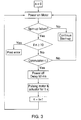
- the firmware first checks feedback singles from the spindle motor to see if an error in the normal start-up sequence of the disk drive has occurred. If an error occurs, the firmware checks whether the error is related to a stiction event, as for example when the commutation count is smaller than or equal to 3. If the error is indeed stiction related, the pulsing sequence will be initiated after a short delay (50 milliseconds, for example). After pulsing the spindle motor and the actuator, the heads should be free from the disk surfaces, and the new trial will be made to spin-up the disks 22. If a trial of the stiction release code failed to break free the heads from the disk surfaces, the stiction release code would be executed up to, for example, 10 times before the drive poses an error in start-up message.
- the frequency at which resonance occurs for the spindle motor is dependent on several drive characteristics, including the moment of inertia of the disk pack and the cumulative adhesive force of each of the stuck heads together.
- the resonant frequencies for the spindle motor will vary depending on how many of the heads 24a-h are actually stuck to disks 22a-d upon the start-up sequence of the drive.
- a disk drive having, for example, eight heads will potentially have eight different resonant frequencies, with the resonant frequency at any given time being determined by the actual number of heads stuck to the disks at that time. Where, for example, there are a large number of heads stuck to the disks, the resonant frequency will be relatively high. Conversely, where there are a small number of heads stuck to the disks, the resonant frequency will be relatively low.
- the present invention contemplates pulsing the spindle motor 29 over a range of discrete frequencies, which range includes at least resonant frequencies of the spindle motor corresponding to 1 head stuck, 2 heads stuck, etc., up to N heads stuck, where N equals the total number of heads in the disk drive.
- Each of the resonant frequencies corresponding to differing numbers of stuck heads may be experimentally determined for a particular disk drive.
- the range of frequencies may include discrete frequency increments that are sufficiently small so as to necessarily include at least the approximate resonant frequencies for the spindle motor corresponding to differing numbers of stuck heads.
- the present invention further contemplates applying a force at the head/disk interface, which force may be applied in a plurality of directions around the head/disk interface.
- stiction in one direction may be smaller than stiction in another direction.
- the heads may be broken free from the disk surfaces in the direction in which stiction is at its minimum.
- the fretting motion of both the spindle motor and the actuator results a force generated in the slider with respect to the disk at each head/disk interface where stiction occurs. Moreover, the direction of this force will vary so as to be applied in a plurality of directions around the head/disk interface(s).
- the resultant forces can be alternatively generated at the head/disk interface in a plurality of directions around the head/disk interface by pulsing the spindle motor and the actuator at a same frequency but with a phase lag of ⁇ /2.
- Another way of generating resultant forces in the plurality of directions is to pulse the spindle motor and the actuator simultaneously at the resonant frequency of the spindle motor. If the pulsing frequencies are close to the resonant frequencies of the motor or the actuator, the forced vibration at these frequencies will have a certain amount of phase lag. This phase lag will result in the resultant forces at the head/disk interface in a plurality of directions.
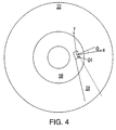
- Both the motor and the actuator are pulsed at ⁇ Hz, while the pulse to the actuator has a phase lag of ⁇ /2. If the frequency of ⁇ Hz is far away from the resonant frequency of the spindle motor or the actuator, the fretting motion of the disks 22 in the circumferential direction, y, (Fig.
- ⁇ is the skew angle of the heads 24 relative to the radial direction
- ⁇ is the pulsing frequency
- t is the time
- a and B are the amplified constants of the spindle motor and the actuator, respectively.
- Both the motor and the actuator are pulsed at ⁇ 1 , ⁇ 2 , ⁇ 3 , ... Hz, sequentially in a reverse order, while the pulse to the actuator has a phase lag of ⁇ /2 but at the same frequency.
- the frequencies of ⁇ 1 , ⁇ 2 , ⁇ 3 ,... Hz are the resonant frequencies of the spindle motor corresponding to one head, two heads, three heads, etc., being stuck to the disk surfaces. These frequencies can be predetermined by experimental measurements. For a 31 ⁇ 2 inch form factor disk drive, for example, the resonant frequencies range from 50 Hz to 400 Hz, while the resonant frequency of the actuator is much higher, around 2 kHz.
- pulsing at the discrete frequencies will have the same effect in generating resultant forces in all the directions. Since the frequencies, ⁇ 1 , ⁇ 2 , ⁇ 3 , ... Hz, are resonant frequencies of the spindle motor corresponding to one head, two heads, three heads, etc., being stuck to the disk surfaces, the firmware essentially issues a pulsing sweep so that the heads can be broken free from the disk surfaces in most efficient way regardless how many heads are stuck to the disk surfaces.
- the motor is pulsed at ⁇ 1 Hz and the actuator is pulsed at ⁇ 2 Hz.
- F y kB cos ⁇ 2 + kA sin ⁇ cos ⁇ 1 t combining equations (9) and (10):
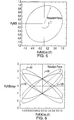
- the contour of the resultant force given by equation (11) may also generate a resultant force through 360° around an ellipse, with the amplitude of the resultant forces changing with time.
Landscapes
- Rotational Drive Of Disk (AREA)
- Supporting Of Heads In Record-Carrier Devices (AREA)
Claims (29)
- Verfahren zum Überwinden von Haftreibung zwischen einem Kopf (24) und einer Platte (22) in einem Plattenlaufwerk (20) mit einer Datenspuren und eine Landezone (58 oder 60) aufweisenden Speicherplatte (22), einem Spindelmotor (29) zum Drehen der Speicherplatte (22), einem Kopf (24) zum Übertragen von Daten an die und von den Datenspuren und der so angeordnet ist, daß er während eines Betriebszeitraums des Plattenlaufwerks (20) über den Datenspuren fliegt und während eines Nichtbetriebszeitraums des Plattenlaufwerks (20) mit der Landezone (58 oder 60) in Kontakt ist, einem Aktuator (28) zum gesteuerten Positionieren des Kopfs (24) an vorgewählten radialen Positionen der Platte (22), die die Datenspuren und die Landezone (58 oder 60) einschließen, und Steuerelektronik zum Steuern des Betriebs des Spindelmotors (29) und des Aktuators (28) durch Senden von Steuersignalen, wobei das Verfahren zum Überwinden von Haftreibung zwischen dem Kopf (24) und der Landezone (58 oder 60) beim Übergang vom Nichtbetrieb zum Betrieb des Plattenlaufwerks (20) durch Betreiben der Steuerelektronik, während des Übergangs vom Nichtbetrieb zum Betrieb des Plattenlaufwerks (20), zum Erzeugen von Steuersignalen den folgenden Schritt aufweist:i) Pulsen des Spindelmotors (29) mit einer ersten vorgewählten Frequenz zum Anlegen einer Kraft, die die Bewegung der Speicherplatte (22) in der Kreisrichtung unterbricht,
und durch die folgenden Schritte gekennzeichnet ist:ii) Pulsen des Aktuators (28) mit einer zweiten vorgewählten Frequenz zum Anlegen einer Kraft, die die Bewegung des Aktuators (28) in der radialen Richtung unterbricht, undiii) Koordinieren des Pulsens des Spindelmotors (29) und des Aktuators (28) zum Erzeugen einer resultierenden Kraft, die auf den Kopf (24) am Kontakt zwischen dem Kopf (24) und der Landezone (58 oder 60) einwirkt, die ihre Winkelrichtung verändert und eine Richtung der geringsten Haftreibung zwischen dem Kopf (24) und der Landezone (58 oder 60) aufweist. - Verfahren nach Anspruch 1, bei dem die erste Frequenz gleich der zweiten Frequenz ist und die zweite Frequenz zur ersten Frequenz phasenverschoben ist.
- Verfahren nach Anspruch 2, bei dem die zweite Frequenz um eine Periode gleich π/2 zur ersten Frequenz phasenverschoben ist.
- Verfahren nach Anspruch 1, bei dem die erste Frequenz gleich der zweiten Frequenz ist, wobei diese Frequenz einen Wert hat, der im wesentlichen nicht gleich einer Resonanzfrequenz des Spindelmotors (29) oder des Aktuators (28) ist.
- Verfahren nach Anspruch 1, bei dem die erste Frequenz gleich der zweiten Frequenz ist, wobei diese Frequenz einen Wert hat, der ungefähr gleich einer Resonanzfrequenz des Spindelmotors (29) oder des Aktuators (28) ist.
- Verfahren nach einem der Ansprüche 4 oder 5, bei dem die zweite Frequenz zur ersten Frequenz phasenverschoben ist.
- Verfahren nach Anspruch 6, bei dem die zweite Frequenz um eine Periode gleich π/2 zur ersten Frequenz phasenverschoben ist.
- Verfahren zum Überwinden von Haftreibung in einem Plattenlaufwerk (20) mit einem Stapel von jeweils Datenspuren und eine Landezone (58 oder 60) aufweisenden Speicherplatten (22), einem Spindelmotor (29) zum Drehen des Stapels von Speicherplatten (22), mehreren Köpfen n (24), wobei jeder der Köpfe (24) zum Übertragen von Daten an die und von den Datenspuren einer entsprechenden des Stapels von Speicherpaltten (22) so angeordnet ist, daß er während eines Betriebszeitraums des Plattenlaufwerks (20) über den Datenspuren fliegt und während eines Nichtbetriebszeitraums des Plattenlaufwerks (20) mit der entsprechenden Landezone (58 oder 60) in Kontakt ist, mehreren Aktuatoren (28) zum gesteuerten Positionieren eines jeweiligen der mehreren Köpfe (24) an vorgewählten radialen Positionen der Platte (22), die dem jeweiligen Kopf (24) entspricht, die die Datenspuren und die Landezone (58 oder 60) einschließen, und Steuerelektronik zum Steuern des Betriebs des Spindelmotors (29) und der Aktuatoren (28) durch Senden von Steuersignalen, wobei das Verfahren zum Überwinden von Haftreibung zwischen den Köpfen (24) und den Landezonen (58 oder 60) beim Übergang vom Nichtbetrieb zum Betrieb des Plattenlaufwerks (20) durch Betreiben der Steuerelektronik, während des Übergangs vom Nichtbetrieb zum Betrieb des Plattenlaufwerks (20), zum Erzeugen von Steuersignalen den folgenden Schritt aufweist:i) Pulsen des Spindelmotors (29) mit jeder eines ersten vorgewählten Satzes von Frequenzen zum Anlegen einer Kraft, die die Bewegung der Speicherplatte (22) in der Kreisrichtung unterbricht,
und durch die folgenden Schritte gekennzeichnet ist:ii) Pulsen des Aktuators (28) mit jeder eines zweiten vorgewählten Satzes von Frequenzen zum Anlegen einer Kraft, die die Bewegung des Aktuators (28) in der radialen Richtung unterbricht, undiii) Koordinieren des Pulsens des Spindelmotors (29) und der Aktuatoren (28) zum Erzeugen einer resultierenden Kraft, die auf den Kopf (24) am Kontakt zwischen dem Kopf (24) und der Landezone (58 oder 60) einwirkt, die ihre Winkelrichtung verändert und eine Richtung der geringsten Haftreibung zwischen dem Kopf (24) und der Landezone (58 oder 60) aufweist. - Verfahren nach Anspruch 8, bei dem der erste vorgewählte Satz von Frequenzen mehrere Frequenzen, die den Resonanzfrequenzen des Spindelmotors (29) entsprechen, enthält, wenn einer oder zwei oder ... n der Köpfe (24) durch Haftreibung auf ihrer entsprechenden Landzone (58 oder 60) gehalten werden.
- Plattenlaufwerk (20) mit:einer Speicherplatte (22) mit Datenspuren und einer Landezone (58 oder 60),einem Spindelmotor (29), der auf Steuersignale anspricht, zum Drehen der Speicherplatte (22),einem Kopf (24) zum Übertragen von Daten von den und auf die Datenspuren, der so angeordnet ist, daß er während eines Betriebszeitraums des Plattenlaufwerks (20) über den Datenspuren fliegt und während eines Nichtbetriebszeitraums des Plattenlaufwerks (20) mit der Landezone (58 oder 60) in Kontakt ist,einem Aktuator (28), der auf Steuersignale anspricht, zum gesteuerten Positionieren des Kopfs (24) an vorgewählten radialen Positionen der Platte (22), die die Datenspuren und die Landezone (58 oder 60) umfassen, undSteuerelektronik, die während eines Übergangs vom Nichtbetrieb zu Betrieb des Plattenlaufwerks (20) zum Erzeugen von Steuersignalen betrieben wird, um:i) den Spindelmotor (29) mit einer ersten vorgewählten Frequenz zu pulsen, um eine Kraft anzulegen, die die Bewegung der Speicherplatte (22) in der Kreisrichtung unterbricht,
dadurch gekennzeichnet, daß die Steuerelektronik weiterhin Steuersignale erzeugt, um:ii) den Aktuator (28) mit einer zweiten vorgewählten Frequenz zum Anlegen einer Kraft zu pulsen, die die Bewegung des Aktuators (28) in der radialen Richtung unterbricht, undiii) das Pulsen des Spindelmotors (29) und des Aktuators (28) zum Erzeugen einer resultierenden Kraft zu koordinieren, die auf den Kopf (24) am Kontakt zwischen dem Kopf (24) und der Landezone (58 oder 60) einwirkt, die ihre Winkelrichtung verändert und eine Richtung der geringsten Haftreibung zwischen dem Kopf (24) und der Landezone (58 oder 60) aufweist. - Plattenlaufwerk nach Anspruch 10, bei dem die erste Frequenz gleich der zweiten Frequenz ist und die zweite Frequenz zur ersten Frequenz phasenverschoben ist.
- Plattenlaufwerk nach Anspruch 11, bei dem die zweite Frequenz um eine Periode gleich π/2 zur ersten Frequenz phasenverschoben ist.
- Plattenlaufwerk nach Anspruch 10, bei dem die erste Frequenz gleich der zweiten Frequenz ist, wobei diese Frequenz einen Wert hat, der im wesentlichen nicht gleich einer Resonanzfrequenz des Spindelmotors (29) oder des Aktuators (28) ist.
- Plattenlaufwerk nach Anspruch 10, bei dem die erste Frequenz gleich der zweiten Frequenz ist, wobei diese Frequenz einen Wert hat, der ungefähr gleich einer Resonanzfrequenz des Spindelmotors (29) oder des Aktuators (28) ist.
- Plattenlaufwerk nach einem der Ansprüche 13 und 14, bei dem die zweite Frequenz zur ersten Frequenz phasenverschoben ist.
- Plattenlaufwerk nach Anspruch 15, bei dem die zweite Frequenz um eine Periode gleich π/2 zur ersten Frequenz phasenverschoben ist.
- Plattenlaufwerk (20) mit:mit einem Stapel von jeweils Datenspuren und eine Landezone (58 oder 60) aufweisenden Speicherplatten (22),einem Spindelmotor (29), der auf Steuersignale anspricht, zum Drehen des Stapels von Speicherplatten (22),mehreren Köpfen (24), wobei jeder der Köpfe (24) zum Übertragen von Daten an die und von den Datenspuren einer entsprechenden des Stapels von Speicherpaltten (22) so angeordnet sind, daß er während eines Betriebszeitraums des Plattenlaufwerks (20) über den entsprechenden Datenspuren fliegt und während eines Nichtbetriebszeitraums des Plattenlaufwerks (20) mit der entsprechenden Landezone (58 bis 60) in Kontakt ist,mehreren Aktuatoren (28), von denen jeder auf Steuersignale anspricht, zum gesteuerten Positionieren eines entsprechenden der mehreren Köpfe (24) an vorgewählten radialen Positionen der Platte (22), die dem entspechenden der Köpfe (24) entsprechen, die die Datenspuren und die Landezone (58 oder 60) umfassen, undSteuerelektronik, die während eines Übergangs vom Nichtbetrieb zu Betrieb des Plattenlaufwerks (20) zum Erzeugen von Steuersignalen betrieben wird, um:i) den Spindelmotor (29) mit jeder eines ersten vorgewählten Satzes von Frequenzen zu pulsen, um eine Kraft anzulegen, die die Bewegung der Speicherplatte (22) in der Kreisrichtung unterbricht,
dadurch gekennzeichnet, daß die Steuerelektronik weiterhin Steuersignale erzeugt, um:ii) den Aktuator (28) mit jeder eines zweiten vorgewählten Satzes von Frequenzen zum Anlegen einer Kraft zu pulsen, die die Bewegung des Aktuators (28) in der radialen Richtung unterbricht, undiii) das Pulsen des Spindelmotors (29) und des Aktuators (28) zum Erzeugen einer resultierenden Kraft zu koordinieren, die auf den Kopf (24) am Kontakt zwischen dem Kopf (24) und der Landezone (58 oder 60) einwirkt, die ihre Winkelrichtung kontinuierlich verändert und eine Richtung der geringsten Haftreibung zwischen dem Kopf (24) und der Landezone (58 oder 60) aufweist. - Plattenlaufwerk (20) nach Anspruch 17, bei dem der erste vorgewählte Satz von Frequenzen mindestens eine Frequenz aufweist, die der Resonanzfrequenz des Spindelmotors (29) entspricht, wenn einer der Köpfe (24) durch Haftreibung auf seiner entsprechenden Landezone (58 oder 60) gehalten wird, wobei eine Frequenz der Resonanzfrequenz des Spindelmotors (29) entspricht, wenn n der Köpfe (24) durch Haftreibung auf ihren entsprechenden Landezonen (58 oder 60) gehalten werden.
- Verfahren zum Überwinden von Haftreibung in einem Plattenlaufwerk (20) mit einem oder mehreren Köpfen (24), die auf einem beweglichen Aktuator (28) angebracht sind zum Übertragen von Daten auf mehrere und von mehreren Platten (22), und einer Motoreinrichtung (29) zum Erzeugen einer relativen Bewegung zwischen einem oder mehreren Köpfen (24) und den mehreren Platten (22), wobei das Verfahren zum Überwinden der Haftreibung zwischen dem einen oder den mehreren Köpfen (24) und den mehreren Platten (22) den Schritt des Pulsens der Motoreinrichtung (29) aufweist und dadurch gekennzeichnet ist, daß sie weiter den folgenden Schritt aufweist: Pulsen des Aktuators (28) mit einer oder unterschiedlichen Frequenzen W1 > W2 zum Verstärken der Kraft, die an Haftreibungsschnittstellen zwischen dem einen oder mehreren Köpfen (24) und entsprechenden Oberflächen der mehreren Speicherplatten (22) wirkt.
- Verfahren zum Überwinden von Haftreibung nach Anspruch 19, wobei die Frequenzen W1 und W2 mindestens annähernde Resonanzfrequenzen der Motoreinrichtung (29) mit einem stekkengebliebenen Kopf, zwei steckengebliebenen Köpfen usw., bis zu N steckengebliebenen Köpfen sind, wobei N gleich der Gesamtzahl der Köpfe (24) des einen oder der mehreren Köpfe ist.
- Verfahren zum Überwinden der Haftreibung in einem Plattenlaufwerk (20) mit einem oder mehreren Köpfen (24), die auf einem beweglichen Aktuator (28) angebracht sind zum Übertragen von Daten auf mehrere und von mehreren Platten (22), und einem Spindelmotor (29) zum Drehen der mehreren Platten (22), wobei das Verfahren zum Überwinden der Haftreibung zwischen dem einen oder den mehreren Köpfen (24) und den mehreren Platten (22) durch die folgenden Schritte gekennzeichnet ist: Pulsen des Spindelmotors (29) über einen Bereich vorbestimmter Frequenzen, wobei die vorbestimmten Frequenzen mindestens annähernde Resonanzfrequenzen des Spindelmotors (29) mit unterschiedlichen Anzahlen von an den mehreren Platten (22) festsitzenden Köpfen (24) sind, und simultanes Pulsen des Aktuators (29) über den Frequenzbereich.
- Verfahren nach Anspruch 21, bei dem die unterschiedliche Anzahl steckenbleibender Köpfe (24) eine Zahl zwischen 1 und N ist, wobei N gleich der Gesamtzahl der Köpfe (24) des einen oder der mehreren Köpfe ist.
- Verfahren nach Anspruch 21, bei dem das Pulsen des Spindelmotors (29) mit einer Frequenz erfolgt, die vierhundert Hertz (400 Hz) nicht übersteigt und nicht kleiner als fünfzig Hertz (50 Hz) ist.
- Verfahren zum Überwinden der Haftreibung in einem Plattenlaufwerk (20) mit einer Kopf- (24) -und-Platten-Anordnung mit einem oder mehreren Köpfen (24) zum Übertragen von Daten auf mehrere und von mehreren Platten (22), einem Spindelmotor (29) zum Drehen der mehreren Platten (22) und einer Aktuatoranordnung (28) zum Positionieren des einen oder der mehreren Köpfe (24) bezüglich der mehreren Platten (22), wobei das Verfahren zum Überwinden der Haftreibung zwischen dem einen oder den mehreren Köpfen (24) und den mehreren Platten (22) durch die folgenden Schritte gekennzeichnet ist:Pulsen des Spindelmotors (29) über einen Bereich diskreter Frequenzen, wobei die diskreten Frequenzen mindestens annähernde Resonanzfrequenzen der Kopf- (24) -und-Platten-Anordnung für 1 bis N steckenbleibende Köpfe sind, wobei N die Gesamtzahl des einen oder der mehreren Köpfe ist, undPulsen der Aktuatoranordnung (28).
- Verfahren nach Anspruch 24, bei dem der Spindelmotor (29) in eine Richtung gepulst wird, die im wesentlichen im rechten Winkel zu der Richtung ist, in der die Aktuatoranordnung (28) gepulst wird.
- Verfahren nach Anspruch 9, mit dem folgenden Schritt: Pulsen des Spindelmotors (29) und des Aktuators (28) mit der gleichen Frequenz.
- Verfahren nach Anspruch 26, bei dem der Motor (29) und der Aktuator (28) mit dem Satz von Frequenzen nacheinander in umgekehrter Reihenfolge von der Resonanzfrequenz, wenn die n Köpfe (24) steckenbleiben, zur Resonanzfrequenz, wenn ein Kopf (24) steckenbleibt, gepulst werden.
- Verfahren nach Anspruch 26, bei dem die zweite Frequenz gegenüber der ersten Frequenz phasenverschoben ist.
- Verfahren nach Anspruch 28, bei dem die zweite Frequenz um eine Periode gleich π/2 zur ersten Frequenz phasenverschoben ist.
Applications Claiming Priority (3)
| Application Number | Priority Date | Filing Date | Title |
|---|---|---|---|
| US37044595A | 1995-01-09 | 1995-01-09 | |
| US370445 | 1995-01-09 | ||
| PCT/US1996/000134 WO1996021927A1 (en) | 1995-01-09 | 1996-01-04 | Disk drive stiction release system |
Publications (2)
| Publication Number | Publication Date |
|---|---|
| EP0803119A1 EP0803119A1 (de) | 1997-10-29 |
| EP0803119B1 true EP0803119B1 (de) | 1998-10-14 |
Family
ID=23459696
Family Applications (1)
| Application Number | Title | Priority Date | Filing Date |
|---|---|---|---|
| EP96905113A Expired - Lifetime EP0803119B1 (de) | 1995-01-09 | 1996-01-04 | Haftfreigabevorrichtung für plattenantrieb |
Country Status (7)
| Country | Link |
|---|---|
| US (1) | US5801505A (de) |
| EP (1) | EP0803119B1 (de) |
| JP (1) | JPH10506217A (de) |
| KR (1) | KR100276754B1 (de) |
| CN (1) | CN1086043C (de) |
| DE (1) | DE69600790T2 (de) |
| WO (1) | WO1996021927A1 (de) |
Families Citing this family (8)
| Publication number | Priority date | Publication date | Assignee | Title |
|---|---|---|---|---|
| KR100194029B1 (ko) * | 1996-12-20 | 1999-06-15 | 윤종용 | 하드디스크 드라이브의 스틱션 에러 검출회로 및 방법 |
| US5982571A (en) * | 1997-06-30 | 1999-11-09 | Quantum Corporation | Disk drive with closed loop commutator and actuator oscillator |
| US6587299B1 (en) | 1999-01-29 | 2003-07-01 | Maxtor Corporation | Method for overcoming a stiction condition in disk drive |
| US6501625B1 (en) * | 1999-06-29 | 2002-12-31 | Hutchinson Technology Incorporated | Disk drive suspension with multi-layered piezoelectric actuator controlled gram load |
| US6882495B2 (en) | 2001-12-10 | 2005-04-19 | Seagate Technology Llc | Wear reduction of a disc surface using an adaptive dither process |
| US20030184907A1 (en) * | 2002-03-29 | 2003-10-02 | Seagate Technology Llc | Method for boosting a disc drive motor stiction breakaway performance |
| US20070268629A1 (en) * | 2006-05-18 | 2007-11-22 | Seagate Technology Llc | Suspension Buckling Limiter |
| US8908317B1 (en) * | 2014-01-27 | 2014-12-09 | Kabushiki Kaisha Toshiba | Method for detecting touchdown of head and disk storage apparatus |
Family Cites Families (5)
| Publication number | Priority date | Publication date | Assignee | Title |
|---|---|---|---|---|
| US4530021A (en) * | 1982-11-26 | 1985-07-16 | International Business Machines Corporation | Micromotion release of heads from lubricated magnetic disks |
| US4532802A (en) * | 1984-05-31 | 1985-08-06 | International Business Machines Corporation | Apparatus for analyzing the interface between a recording disk and a read-write head |
| US4970610A (en) * | 1988-10-04 | 1990-11-13 | International Business Machines Corporation | Magnetic disk drive start procedure for starting reaction torque amplification |
| EP0573964B1 (de) * | 1992-06-08 | 1998-11-25 | Hewlett-Packard Company | Bipolares System zur Erzeugung eines auf eine Platte eines Laufwerkes wirkenden Drehmoments zum Lösen festgefahrener Wandlerköpfe |
| US5384675A (en) * | 1993-09-08 | 1995-01-24 | International Business Machines Corporation | Disk drive with controlled actuator oscillation for release of head carriers |
-
1996
- 1996-01-04 KR KR1019970704658A patent/KR100276754B1/ko not_active Expired - Fee Related
- 1996-01-04 EP EP96905113A patent/EP0803119B1/de not_active Expired - Lifetime
- 1996-01-04 CN CN96191939A patent/CN1086043C/zh not_active Expired - Fee Related
- 1996-01-04 JP JP8521745A patent/JPH10506217A/ja active Pending
- 1996-01-04 WO PCT/US1996/000134 patent/WO1996021927A1/en not_active Ceased
- 1996-01-04 DE DE69600790T patent/DE69600790T2/de not_active Expired - Fee Related
-
1997
- 1997-04-23 US US08/835,837 patent/US5801505A/en not_active Expired - Lifetime
Also Published As
| Publication number | Publication date |
|---|---|
| DE69600790T2 (de) | 1999-03-25 |
| KR19980701269A (ko) | 1998-05-15 |
| JPH10506217A (ja) | 1998-06-16 |
| CN1174625A (zh) | 1998-02-25 |
| US5801505A (en) | 1998-09-01 |
| DE69600790D1 (de) | 1998-11-19 |
| KR100276754B1 (ko) | 2001-01-15 |
| HK1003675A1 (en) | 1998-11-06 |
| CN1086043C (zh) | 2002-06-05 |
| WO1996021927A1 (en) | 1996-07-18 |
| EP0803119A1 (de) | 1997-10-29 |
Similar Documents
| Publication | Publication Date | Title |
|---|---|---|
| US5384675A (en) | Disk drive with controlled actuator oscillation for release of head carriers | |
| US6476996B1 (en) | Disk drive comprising an actuator driver circuit for retracting a head independent of a servo microprocessor when a spindle speed fault mode is detected | |
| EP0089957B1 (de) | System zum zurückziehen eines magnetkopfes im notfall | |
| US4530021A (en) | Micromotion release of heads from lubricated magnetic disks | |
| EP0184387B1 (de) | Methode zur Steuerung des Betriebs eines Plattenspeichers und ein Plattenspeicher | |
| US5798884A (en) | Multiple zone data storage system and method | |
| US5801505A (en) | Disk drive stiction release system | |
| US6016234A (en) | Actuator retract/unload system for low power disk drives | |
| JP2524481B2 (ja) | ディスク・ドライブおよび始動方法 | |
| US5157560A (en) | Data recording and reproducing device designed to reduce power consumption | |
| JP2001307409A (ja) | 記録再生装置 | |
| US20030184907A1 (en) | Method for boosting a disc drive motor stiction breakaway performance | |
| HK1003675B (en) | Disk drive stiction release system | |
| JP2722565B2 (ja) | ディスク装置 | |
| US6292323B1 (en) | Method and apparatus for removing accumulated particles on a head in an information recording and reproducing apparatus | |
| US7095201B1 (en) | Method and apparatus for providing a user selectable start-up current in a disk drive | |
| US20020135924A1 (en) | Multi-phase acceleration of a data storage disc | |
| US20060221490A1 (en) | Ramp unload in disc drives | |
| JP2658447B2 (ja) | スライダーのローディング方法 | |
| JP2734142B2 (ja) | スライダーのアンロード方法 | |
| JP3030273B2 (ja) | ディスク・ドライブ装置及びこれの制御方法 | |
| JP2000057714A (ja) | ディスク記憶装置及び同装置に適用するヘッド・アンロード装置 | |
| KR100506262B1 (ko) | 액츄에이터 언래칭 제어방법 | |
| JP2970061B2 (ja) | 磁気ディスク装置 | |
| KR20040007470A (ko) | 데이터 저장 디스크의 다단계 가속방법 |
Legal Events
| Date | Code | Title | Description |
|---|---|---|---|
| PUAI | Public reference made under article 153(3) epc to a published international application that has entered the european phase |
Free format text: ORIGINAL CODE: 0009012 |
|
| 17P | Request for examination filed |
Effective date: 19970723 |
|
| AK | Designated contracting states |
Kind code of ref document: A1 Designated state(s): DE GB |
|
| 17Q | First examination report despatched |
Effective date: 19971125 |
|
| GRAG | Despatch of communication of intention to grant |
Free format text: ORIGINAL CODE: EPIDOS AGRA |
|
| GRAG | Despatch of communication of intention to grant |
Free format text: ORIGINAL CODE: EPIDOS AGRA |
|
| GRAH | Despatch of communication of intention to grant a patent |
Free format text: ORIGINAL CODE: EPIDOS IGRA |
|
| GRAH | Despatch of communication of intention to grant a patent |
Free format text: ORIGINAL CODE: EPIDOS IGRA |
|
| GRAA | (expected) grant |
Free format text: ORIGINAL CODE: 0009210 |
|
| AK | Designated contracting states |
Kind code of ref document: B1 Designated state(s): DE GB |
|
| REF | Corresponds to: |
Ref document number: 69600790 Country of ref document: DE Date of ref document: 19981119 |
|
| PLBE | No opposition filed within time limit |
Free format text: ORIGINAL CODE: 0009261 |
|
| STAA | Information on the status of an ep patent application or granted ep patent |
Free format text: STATUS: NO OPPOSITION FILED WITHIN TIME LIMIT |
|
| 26N | No opposition filed | ||
| REG | Reference to a national code |
Ref country code: GB Ref legal event code: 732E |
|
| REG | Reference to a national code |
Ref country code: GB Ref legal event code: IF02 |
|
| PGFP | Annual fee paid to national office [announced via postgrant information from national office to epo] |
Ref country code: GB Payment date: 20040106 Year of fee payment: 9 |
|
| PGFP | Annual fee paid to national office [announced via postgrant information from national office to epo] |
Ref country code: DE Payment date: 20040129 Year of fee payment: 9 |
|
| PG25 | Lapsed in a contracting state [announced via postgrant information from national office to epo] |
Ref country code: GB Free format text: LAPSE BECAUSE OF NON-PAYMENT OF DUE FEES Effective date: 20050104 |
|
| PG25 | Lapsed in a contracting state [announced via postgrant information from national office to epo] |
Ref country code: DE Free format text: LAPSE BECAUSE OF NON-PAYMENT OF DUE FEES Effective date: 20050802 |
|
| GBPC | Gb: european patent ceased through non-payment of renewal fee |
Effective date: 20050104 |