EP0803037B1 - Ventilgehäuse aus metall und kernform zu dessen herstellung - Google Patents
Ventilgehäuse aus metall und kernform zu dessen herstellung Download PDFInfo
- Publication number
- EP0803037B1 EP0803037B1 EP95940240A EP95940240A EP0803037B1 EP 0803037 B1 EP0803037 B1 EP 0803037B1 EP 95940240 A EP95940240 A EP 95940240A EP 95940240 A EP95940240 A EP 95940240A EP 0803037 B1 EP0803037 B1 EP 0803037B1
- Authority
- EP
- European Patent Office
- Prior art keywords
- control
- valve housing
- outer circumference
- metal rings
- metal
- Prior art date
- Legal status (The legal status is an assumption and is not a legal conclusion. Google has not performed a legal analysis and makes no representation as to the accuracy of the status listed.)
- Expired - Lifetime
Links
Images

Classifications
-
- B—PERFORMING OPERATIONS; TRANSPORTING
- B22—CASTING; POWDER METALLURGY
- B22C—FOUNDRY MOULDING
- B22C7/00—Patterns; Manufacture thereof so far as not provided for in other classes
- B22C7/06—Core boxes
-
- B—PERFORMING OPERATIONS; TRANSPORTING
- B22—CASTING; POWDER METALLURGY
- B22D—CASTING OF METALS; CASTING OF OTHER SUBSTANCES BY THE SAME PROCESSES OR DEVICES
- B22D19/00—Casting in, on, or around objects which form part of the product
-
- F—MECHANICAL ENGINEERING; LIGHTING; HEATING; WEAPONS; BLASTING
- F16—ENGINEERING ELEMENTS AND UNITS; GENERAL MEASURES FOR PRODUCING AND MAINTAINING EFFECTIVE FUNCTIONING OF MACHINES OR INSTALLATIONS; THERMAL INSULATION IN GENERAL
- F16K—VALVES; TAPS; COCKS; ACTUATING-FLOATS; DEVICES FOR VENTING OR AERATING
- F16K27/00—Construction of housing; Use of materials therefor
- F16K27/04—Construction of housing; Use of materials therefor of sliding valves
- F16K27/041—Construction of housing; Use of materials therefor of sliding valves cylindrical slide valves
Definitions
- the invention relates to a valve housing made of metal with highly stressed housing areas and the features from the preamble of claim 1.
- a slide valve with such a valve housing is for example from DE 36 44 269 Al known.
- the housing webs are made entirely of cast iron. During machining and also during operation there is a risk that cast iron material breaks away and the valve housing can no longer be used.
- the housing is known to be lined with a material resistant to the medium (DE 26 48 729 A1). In this known valve, the housing is only used for support the lining.
- valve housing In a directional valve housing according to DE 21 61 386 C2, the valve housing is made made of plastic, the metallic parts intended for the valve function such as guide bushing with control edges for the control piston and supply and discharge lines encloses and receives the mounting plate.
- DE 12 95 944 known a valve lifter, which is made as a composite body made of cast iron and steel is. The cast iron section is attached to the steel section by suitable measures cast on.
- valve seat In a seat valve known from FR-A 2 596 487, the valve seat is replaced by a cast metal ring formed.
- the one axial end face of the metal ring is different than with a slide valve inevitably free of casting material, since there Locking member must sit on the seat.
- the free end face on the metal ring the valve according to FR-A 2 596 487 corresponds to the cylindrical one with a slide valve Inner surface of the housing webs on which the control piston is guided.
- a valve arrangement known from US-A 4,516,594 contains several seat valves with cast-in valve seats also a slide valve with a control piston. This is located in a control bore, which is partially cast through Bush made of a material that is more resistant to the casting material is formed.
- the socket is provided with a recess on the inside, which as the Bushing around the control room.
- the two housing bars and the floor, which delimit the control chamber axially and radially, are therefore in one piece trained with each other. Such a design allows only a limited one radial depth of the control room.
- US-A 4 516 594 the thought of a plurality of wear resistant limbs before potting to form a single component.
- the invention has for its object a valve housing according to the preamble of claim 1 to develop so that it is possible in the finishing resulting committee to reduce the service life of the control edges extend and larger cross-sections of the control rooms for given external dimensions the valve body.
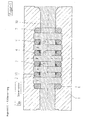
- the housing body of a directional control valve is cast from cast iron designated that a rotating pump control room P, not shown Consumer-related work control rooms A, B and two external ones Has tank control rooms T.
- the control rooms are through by each other Steel rings formed housing webs 2, 3, 4, 5 separately and the outside Tank control rooms T are bounded on the outside by steel rings 6 and 7.
- the steel rings 2-5 are on three sides and the steel rings 6 and 7 on two sides of the sand core 10 enclosed and introduced together with the sand core in the housing mold been.
- the free outer peripheral surface 11 of the steel rings is during the casting process with the liquid cast iron by fusing with the housing body 1 connected. After removal of the sand core 10, the inner densely hatched area 13 of the steel rings finished.
- the areas 13 are not used to guide the shown control piston and as control edges with corresponding control edges of the control piston, not shown, interact by adjacent control rooms A-T, P-B or P-A, B-T in one or the other flow direction of the medium be connected to each other.
- the measurement of the steel rings for their finishing can because of the greater strength and dimensional accuracy are kept smaller than at Cast iron. This results in larger control rooms and correspondingly smaller ones Flow losses.
- the control edges and guide surfaces of the Steel rings for the control piston are hardened afterwards, if necessary should be. Since the cast material is irrelevant for the control function, it can are of lower quality.
- the core shape 40 shown in FIG. 2 shows in the lower half 40a for receiving and simultaneous fixation of the steel rings 42 circumferential trapezoidal projections 43, which engage in circumferential grooves 44 of the steel rings.
- the grooves can be as shown have different profiles. These profiles are made during the casting process filled with liquid iron so that the rings after the cast iron solidified are firmly and tightly anchored in the housing body.
- This also applies to alternative to Grooves possible circumferential projections 46 on the outer circumference of the rings accordingly the upper half 40b of the core shape.
- the core shape has circumferential Grooves 47 for receiving the projections of the rings.
- the same groove profile or projection profile in the core shape can have different profile configurations of the projections or grooves on the circumference of the ring.
- the rings By profiling the outer circumference of the rings and the like Training of receiving profiles in the core shape, the rings sit during the Shooting the core firmly in the core shape.
- the closely hatched areas 48 of the rings form the control edges, which with corresponding control edges on Control pistons, not shown, work together and the particularly highly stressed Places in the valve housing.
Landscapes
- Engineering & Computer Science (AREA)
- Mechanical Engineering (AREA)
- General Engineering & Computer Science (AREA)
- Valve Housings (AREA)
- Molds, Cores, And Manufacturing Methods Thereof (AREA)
Abstract
Description
- Figur 1
- einen Axialschnitt durch ein abgegossenes Wegeventilgehäuse mit Sandkern und
- Figur 2
- einen Axialschnitt durch eine Kernform für das Wegeventilgehäuse nach Figur 1.
Claims (10)
- Ventilgehäuse aus Metall für eine hydraulisches Schieberventil mit einem gegossenen Gehäusekörper (1), in dem sich eine Steuerbohrung zur Aufnahme eines in der Steuerbohrung axial verschiebbaren Steuerkolbens befindet, wobei an der Steuerbohrung mehrere axial voneinander beabstandete Steuerräume (A, B, P, T) ringförmig herumlaufen, die durch Gehäusestege voneinander getrennt sind, die zur Bildung von Steuerkanten (13) an ihrer der Steuerbohrung zugewandten Innenseite und in einem Steuerkantenbereich begrenzter radialer Tiefe an zumindest einer ihrer axialen Stirnseiten fertigbearbeitet sind,
dadurch gekennzeichnet, daß jeder der mehreren Gehäusestege zumindest im Bereich der Fertigbearbeitung aus einem selbständigen Metallring (2, 3, 4, 5, 42) gebildet ist, der aus einem der Beanspruchung weitgehend standhaltendem Material besteht und, beim Guß des Gehäusekörpers (1) mit dem Gehäusekörper (1) verbunden worden ist,
wobei die Metallringe (2, 3, 4, 5, 42) eine einen Steuerraum (A, B, P, T) axial begrenzende Stirnfläche besitzen, die über den Bereich der Fertigbearbeitung hinaus frei von Gußmaterial ist. - Ventilgehäuse nach Anspruch 1, dadurch gekennzeichnet, daß die Stirnflächen der Metallringe (2, 3, 4, 5, 42) bis zu einer Kante zwischen einer Stirnfläche und dem Außenumfang der Metallringe (2, 3, 4, 5, 42) frei von Gußmaterial sind und daß die Metallringe (2, 3, 4, 5, 42) an ihrem Außenumfang am Gußkörper (1) axial gehalten sind.
- Ventilgehäuse nach Anspruch 1 oder 2, dadurch gekennzeichnet, daß die Metallringe (2, 3, 4, 5, 42) durch Anschmelzen beim Guß an den Berührungsstellen mit dem Gehäusekörper (1) stoffschlüssig verbunden sind.
- Ventilgehäuse nach einem vorhergehenden Anspruch, dadurch gekennzeichnet, daß die Metallringe (2, 3, 4, 5, 42) am Außenumfang eine Ausnehmung (44) oder einen Vorsprung (46) aufweisen.
- Ventilgehäuse nach Anspruch 4, dadurch gekennzeichnet, daß die Metallringe (2, 3, 4, 5, 42) wenigstens eine an ihrem Außenumfang umlaufende Nut (44) aufweisen.
- Ventilgehäuse nach Anspruch 4, dadurch gekennzeichnet, daß die Metallringe (2, 3, 4, 5, 42) wenigstens einen an ihrem Außenumfang umlaufenden Steg (46) aufweisen.
- Ventilgehäuse nach Anspruch 2, dadurch gekennzeichnet, daß die Steuerräume (A, B, P, T) radial tiefer reichen als die Kante zwischen den freien Stirnflächen und dem Außenumfang der angrenzenden Metallringe (2, 3, 4, 5, 42) und daß die Steuerräume (A, B, P, T) außerhalb der Kante die gleiche axiale Breite wie im Bereich der Metallringe (2, 3, 4, 5, 42) haben.
- Ventilgehäuse nach einem vorhergehenden Anspruch, dadurch gekennzeichnet, daß, axial gesehen, zwei äußere Steuerräume (T) und wenigstens ein innerer Steuerraum (A, B, P) vorhanden sind und daß die äußeren Steuerräume (T) auch an der vom inneren Steuerraum (A, B, P) aus gesehen äußeren Seite durch einen eingegossenen Metallring (6, 7, 42) axial begrenzt sind.
- Kernform (40 )zur Herstellung eines Ventilgehäuses gemäß Anspruch 4, dadurch gekennzeichnet, daß sie zur Aufnahme und Festlegung eines Metallrings (2, 3, 4, 5, 42) eine einen Vorsprung (46) am Außenumfang des Metallrings (2, 3, 4, 5, 42) aufnehmende Ausnehmung (47) oder einen in eine Ausnehmung (44) am Außenumfang des Metallrings (2, 3, 4, 5, 42) eintauchenden Vorsprung (43) aufweist.
- Kernform (40) nach Anspruch 9, dadurch gekennzeichnet, daß deren Ausnehmung (47) oder Vorsprung (43) einen trapezförmigen Querschnitt aufweist.
Applications Claiming Priority (3)
| Application Number | Priority Date | Filing Date | Title |
|---|---|---|---|
| DE19500605A DE19500605A1 (de) | 1995-01-11 | 1995-01-11 | Gegossener Gehäusekörper |
| DE19500605 | 1995-01-11 | ||
| PCT/EP1995/004633 WO1996021818A1 (de) | 1995-01-11 | 1995-11-24 | Ventilgehäuse aus metall |
Publications (2)
| Publication Number | Publication Date |
|---|---|
| EP0803037A1 EP0803037A1 (de) | 1997-10-29 |
| EP0803037B1 true EP0803037B1 (de) | 2000-01-19 |
Family
ID=7751273
Family Applications (1)
| Application Number | Title | Priority Date | Filing Date |
|---|---|---|---|
| EP95940240A Expired - Lifetime EP0803037B1 (de) | 1995-01-11 | 1995-11-24 | Ventilgehäuse aus metall und kernform zu dessen herstellung |
Country Status (5)
| Country | Link |
|---|---|
| US (1) | US5911407A (de) |
| EP (1) | EP0803037B1 (de) |
| JP (1) | JP3759614B2 (de) |
| DE (2) | DE19500605A1 (de) |
| WO (1) | WO1996021818A1 (de) |
Families Citing this family (10)
| Publication number | Priority date | Publication date | Assignee | Title |
|---|---|---|---|---|
| DE19701085A1 (de) * | 1997-01-15 | 1998-07-16 | Kolbenschmidt Ag | Verfahren und Anordnung zum Herstellen eines Ringträgerkolbens |
| DE19703399A1 (de) * | 1997-01-30 | 1998-08-06 | Itt Mfg Enterprises Inc | Verfahren zur Herstellung eines Gehäuseblocks für ein Hydraulikaggregat |
| GB2352664A (en) * | 1999-07-06 | 2001-02-07 | Ford Global Tech Inc | Engine shaft casting process including preformed slug member |
| DE10119271A1 (de) * | 2001-04-20 | 2002-10-24 | Zahnradfabrik Friedrichshafen | Regelventil |
| US20040238780A1 (en) * | 2003-06-02 | 2004-12-02 | Gethmann Doug P. | Control valve with integrated hardened valve seat |
| EP2319639A1 (de) | 2009-11-10 | 2011-05-11 | Georg Fischer Automobilguss GmbH | Guss-Achsschenkel mit eingegossenen Stahlkern - Verfahren zur Herstellung des Achsschenkels |
| DE102011076048A1 (de) * | 2011-05-18 | 2012-11-22 | Bosch Mahle Turbo Systems Gmbh & Co. Kg | Ladeeinrichtung |
| DE102014202744A1 (de) * | 2014-02-14 | 2015-08-20 | Siemens Aktiengesellschaft | Schutz vor Erosion und Erosionskorrosion an Stegen von Gußgehäusen |
| CN111649020A (zh) * | 2020-06-08 | 2020-09-11 | 南通华东油压科技有限公司 | 工程机械用主控制阀体及其浇铸方法 |
| CN112756586B (zh) * | 2020-12-22 | 2022-06-14 | 湖南江滨机器(集团)有限责任公司 | 一种浇铸带空腔的铸铁镶环的模具和工艺方法 |
Family Cites Families (22)
| Publication number | Priority date | Publication date | Assignee | Title |
|---|---|---|---|---|
| AT85911B (de) * | 1919-05-07 | 1921-10-25 | Wilhelm Klepsch | Verfahren zur Herstellung von Ventilen und Hähnen. |
| BE426206A (de) * | 1937-02-06 | |||
| DE728783C (de) * | 1941-05-24 | 1942-12-03 | Bopp & Reuther Gmbh | Absperschiebergehaeuse |
| DE826223C (de) * | 1950-09-30 | 1951-12-27 | Neue Argus Ges M B H | Absperrhahn, insbesondere mit kugelfoermigem Abschlusskoerper, und Verfahren zu seiner Herstellung |
| US2739613A (en) * | 1952-01-24 | 1956-03-27 | Kulikoff Waldemar | Switches for hydraulic pressure devices |
| US2935596A (en) * | 1957-12-30 | 1960-05-03 | Earl A Thompson | Fusing machine |
| DE1247064B (de) * | 1960-06-02 | 1967-08-10 | Fuchs Fa Otto | Kurbelgehaeuse aus Leichtmetallguss |
| DE1425123A1 (de) * | 1962-11-20 | 1969-02-20 | Schmidt Gmbh Karl | Kurbelgehaeuse mit eingegossenen Stahlringen |
| SE325377B (de) * | 1968-04-10 | 1970-06-29 | Hykon Patent Ab | |
| DE1954799A1 (de) * | 1969-10-31 | 1971-05-06 | Hellmut Schoeler | Ventilkoerper mit Giessharzeinlage fuer Hydraulik- und Pneumatikventile u.dgl. |
| DE2131526B2 (de) * | 1971-06-25 | 1975-05-22 | Lohse, Martin, 7920 Heidenheim | Flachschieber für Werkstoffverschleie verursachende Stoffströme |
| DE2161386C2 (de) * | 1971-12-10 | 1983-08-11 | Hartmann & Lämmle GmbH & Co KG, 7255 Rutesheim | Ventilgehäuse, insbesondere hydraulisches Wegeventilgehäuse |
| FR2225669B1 (de) * | 1973-04-13 | 1976-06-11 | Malbranque Serseg | |
| DE2631993C3 (de) * | 1976-07-16 | 1980-05-29 | J. Lorch Gesellschaft & Co Kg, 7035 Waldenbuch | Kunststoffteil, wie Gehäuse, mit einem Verstärkungsteil |
| DE2648729A1 (de) * | 1976-10-27 | 1978-05-03 | Francesco Ortu | Verfahren zur herstellung von ausgekleideten metallstuecken und auf diese weise erhaltenen artikeln |
| DE2658491A1 (de) * | 1976-12-23 | 1978-06-29 | Blank Karl | Dichtring |
| US4516594A (en) * | 1984-04-03 | 1985-05-14 | Diesel Equipment Limited | Multi-part valve with a valve seat skeleton and cast valve body |
| FR2594518B3 (fr) * | 1986-02-17 | 1988-02-12 | Feurs Fonderies Acieries Elect | Bague d'etancheite et son application a la mise en oeuvre d'un procede de fabrication d'un corps moule pour faire office de siege a un organe obturateur notamment de robinetterie |
| FR2596487A1 (fr) * | 1986-03-27 | 1987-10-02 | Sereg Soc | Procede de realisation d'un composant de robinetterie et composant de robinetterie obtenu par la mise en oeuvre dudit procede |
| DE3644269A1 (de) * | 1986-12-23 | 1988-07-07 | Rexroth Mannesmann Gmbh | Wegeventil |
| DE9317131U1 (de) * | 1993-11-09 | 1994-01-27 | Rafeld Kunststofftechnik GmbH & Co. KG, 87640 Biessenhofen | Schrägsitzventil |
| DE9407083U1 (de) * | 1994-04-28 | 1994-07-07 | Festo Kg, 73734 Esslingen | Kolbenschieberventil |
-
1995
- 1995-01-11 DE DE19500605A patent/DE19500605A1/de not_active Withdrawn
- 1995-11-24 DE DE59507659T patent/DE59507659D1/de not_active Expired - Lifetime
- 1995-11-24 US US08/875,332 patent/US5911407A/en not_active Expired - Fee Related
- 1995-11-24 JP JP52139296A patent/JP3759614B2/ja not_active Expired - Fee Related
- 1995-11-24 EP EP95940240A patent/EP0803037B1/de not_active Expired - Lifetime
- 1995-11-24 WO PCT/EP1995/004633 patent/WO1996021818A1/de not_active Ceased
Also Published As
| Publication number | Publication date |
|---|---|
| WO1996021818A1 (de) | 1996-07-18 |
| JPH10512035A (ja) | 1998-11-17 |
| DE19500605A1 (de) | 1996-07-18 |
| US5911407A (en) | 1999-06-15 |
| EP0803037A1 (de) | 1997-10-29 |
| JP3759614B2 (ja) | 2006-03-29 |
| DE59507659D1 (de) | 2000-02-24 |
Similar Documents
| Publication | Publication Date | Title |
|---|---|---|
| DE10196542B4 (de) | Metalldichtung | |
| DE3518721C2 (de) | ||
| DE69204515T2 (de) | Zusammengesetzer Ölring. | |
| EP0803037B1 (de) | Ventilgehäuse aus metall und kernform zu dessen herstellung | |
| EP0189767B1 (de) | Ölgekühlter, mehrteiliger Tauchkolben für Hubkolbenbrennkraftmaschinen | |
| DE10352244A1 (de) | Verfahren zur Herstellung eines Kolbens für einen Verbrennungsmotor | |
| DE69203463T2 (de) | Brennkraftmaschine und metallische Abdichtung zur Anwendung in solcher Maschine. | |
| DE3904240A1 (de) | Kompressor fuer klimaanlagen mit taumelscheibenanordnung | |
| EP2814636B1 (de) | Verfahren zum erhöhen der festigkeit von wellen, insbesondere von kurbelwellen | |
| DE3027352A1 (de) | Kolben mit panzerung der kolbenringnuten | |
| DE3919267C2 (de) | Radialkolbenpumpe mit Ventilkolbeneinsatz | |
| DE2716888A1 (de) | Radialkolbenpumpe | |
| DE3205952A1 (de) | Nockenwelle | |
| DE102004038465A1 (de) | Kolben, insbesondere Kühlkanalkolben einer Brennkraftmaschine, mit zumindest drei Reibschweißzonen | |
| DE10219779A1 (de) | Verfahren zur Herstellung eines Kolbens und nach dem Verfahren hergestellter Kolben | |
| EP1180592B1 (de) | Stahlkolben | |
| DE19725563A1 (de) | Radialkolbenpumpe | |
| DE4433801C1 (de) | Lagergestell für eine Brennkraftmaschine | |
| DE19755557C1 (de) | Gießform zur Herstellung eines Motorblocks | |
| WO2001091947A1 (de) | Zylinderkurbelgehäuse für eine brennkraftmaschine | |
| DE2546388A1 (de) | Gebauter kolben | |
| EP0291867B1 (de) | Hubkolbenmaschine | |
| DE3822329C2 (de) | ||
| DE3931678C2 (de) | Zylinderblock für eine wassergekühlte Mehrzylinder-Brennkraftmaschine | |
| DE20307327U1 (de) | Kolbenvakuumpumpenserie |
Legal Events
| Date | Code | Title | Description |
|---|---|---|---|
| PUAI | Public reference made under article 153(3) epc to a published international application that has entered the european phase |
Free format text: ORIGINAL CODE: 0009012 |
|
| 17P | Request for examination filed |
Effective date: 19970719 |
|
| AK | Designated contracting states |
Kind code of ref document: A1 Designated state(s): DE FR GB IT LU |
|
| 17Q | First examination report despatched |
Effective date: 19980112 |
|
| GRAG | Despatch of communication of intention to grant |
Free format text: ORIGINAL CODE: EPIDOS AGRA |
|
| GRAG | Despatch of communication of intention to grant |
Free format text: ORIGINAL CODE: EPIDOS AGRA |
|
| GRAG | Despatch of communication of intention to grant |
Free format text: ORIGINAL CODE: EPIDOS AGRA |
|
| GRAH | Despatch of communication of intention to grant a patent |
Free format text: ORIGINAL CODE: EPIDOS IGRA |
|
| RAP1 | Party data changed (applicant data changed or rights of an application transferred) |
Owner name: MANNESMANN REXROTH AKTIENGESELLSCHAFT |
|
| GRAH | Despatch of communication of intention to grant a patent |
Free format text: ORIGINAL CODE: EPIDOS IGRA |
|
| GRAA | (expected) grant |
Free format text: ORIGINAL CODE: 0009210 |
|
| AK | Designated contracting states |
Kind code of ref document: B1 Designated state(s): DE FR GB IT LU |
|
| ITF | It: translation for a ep patent filed | ||
| REF | Corresponds to: |
Ref document number: 59507659 Country of ref document: DE Date of ref document: 20000224 |
|
| GBT | Gb: translation of ep patent filed (gb section 77(6)(a)/1977) |
Effective date: 20000417 |
|
| ET | Fr: translation filed | ||
| PLBE | No opposition filed within time limit |
Free format text: ORIGINAL CODE: 0009261 |
|
| STAA | Information on the status of an ep patent application or granted ep patent |
Free format text: STATUS: NO OPPOSITION FILED WITHIN TIME LIMIT |
|
| PG25 | Lapsed in a contracting state [announced via postgrant information from national office to epo] |
Ref country code: LU Free format text: LAPSE BECAUSE OF NON-PAYMENT OF DUE FEES Effective date: 20001124 |
|
| 26N | No opposition filed | ||
| REG | Reference to a national code |
Ref country code: GB Ref legal event code: IF02 |
|
| PGFP | Annual fee paid to national office [announced via postgrant information from national office to epo] |
Ref country code: FR Payment date: 20031013 Year of fee payment: 9 |
|
| PGFP | Annual fee paid to national office [announced via postgrant information from national office to epo] |
Ref country code: GB Payment date: 20031120 Year of fee payment: 9 |
|
| PG25 | Lapsed in a contracting state [announced via postgrant information from national office to epo] |
Ref country code: GB Free format text: LAPSE BECAUSE OF NON-PAYMENT OF DUE FEES Effective date: 20041124 |
|
| GBPC | Gb: european patent ceased through non-payment of renewal fee |
Effective date: 20041124 |
|
| PG25 | Lapsed in a contracting state [announced via postgrant information from national office to epo] |
Ref country code: FR Free format text: LAPSE BECAUSE OF NON-PAYMENT OF DUE FEES Effective date: 20050729 |
|
| REG | Reference to a national code |
Ref country code: FR Ref legal event code: ST |
|
| PGFP | Annual fee paid to national office [announced via postgrant information from national office to epo] |
Ref country code: IT Payment date: 20091128 Year of fee payment: 15 |
|
| PGFP | Annual fee paid to national office [announced via postgrant information from national office to epo] |
Ref country code: DE Payment date: 20110125 Year of fee payment: 16 |
|
| PG25 | Lapsed in a contracting state [announced via postgrant information from national office to epo] |
Ref country code: IT Free format text: LAPSE BECAUSE OF NON-PAYMENT OF DUE FEES Effective date: 20101124 |
|
| REG | Reference to a national code |
Ref country code: DE Ref legal event code: R119 Ref document number: 59507659 Country of ref document: DE Effective date: 20120601 |
|
| PG25 | Lapsed in a contracting state [announced via postgrant information from national office to epo] |
Ref country code: DE Free format text: LAPSE BECAUSE OF NON-PAYMENT OF DUE FEES Effective date: 20120601 |