EP0802839B1 - Process for introducing cores into a casting mould - Google Patents
Process for introducing cores into a casting mould Download PDFInfo
- Publication number
- EP0802839B1 EP0802839B1 EP96924883A EP96924883A EP0802839B1 EP 0802839 B1 EP0802839 B1 EP 0802839B1 EP 96924883 A EP96924883 A EP 96924883A EP 96924883 A EP96924883 A EP 96924883A EP 0802839 B1 EP0802839 B1 EP 0802839B1
- Authority
- EP
- European Patent Office
- Prior art keywords
- core
- cores
- bracing
- core group
- template
- Prior art date
- Legal status (The legal status is an assumption and is not a legal conclusion. Google has not performed a legal analysis and makes no representation as to the accuracy of the status listed.)
- Expired - Lifetime
Links
- 238000000034 method Methods 0.000 title claims abstract description 29
- 238000005266 casting Methods 0.000 title claims abstract description 25
- 239000000853 adhesive Substances 0.000 claims abstract description 4
- 230000001070 adhesive effect Effects 0.000 claims abstract description 4
- 238000003780 insertion Methods 0.000 claims description 3
- 230000037431 insertion Effects 0.000 claims description 3
- 238000001035 drying Methods 0.000 abstract description 8
- 238000005304 joining Methods 0.000 abstract description 3
- 238000007598 dipping method Methods 0.000 abstract 2
- 238000013459 approach Methods 0.000 description 8
- 238000013461 design Methods 0.000 description 8
- 230000015572 biosynthetic process Effects 0.000 description 5
- 238000004519 manufacturing process Methods 0.000 description 5
- 239000003292 glue Substances 0.000 description 4
- 238000004513 sizing Methods 0.000 description 4
- 229910001060 Gray iron Inorganic materials 0.000 description 2
- 238000005516 engineering process Methods 0.000 description 2
- 238000012545 processing Methods 0.000 description 2
- 238000004026 adhesive bonding Methods 0.000 description 1
- 238000007605 air drying Methods 0.000 description 1
- 238000004140 cleaning Methods 0.000 description 1
- 239000011248 coating agent Substances 0.000 description 1
- 238000000576 coating method Methods 0.000 description 1
- 238000011161 development Methods 0.000 description 1
- 230000018109 developmental process Effects 0.000 description 1
- 238000010586 diagram Methods 0.000 description 1
- 230000009189 diving Effects 0.000 description 1
- 239000002184 metal Substances 0.000 description 1
- 229910052751 metal Inorganic materials 0.000 description 1
- 238000000465 moulding Methods 0.000 description 1
- 238000012805 post-processing Methods 0.000 description 1
- 230000007704 transition Effects 0.000 description 1
Images
Classifications
-
- B—PERFORMING OPERATIONS; TRANSPORTING
- B22—CASTING; POWDER METALLURGY
- B22C—FOUNDRY MOULDING
- B22C9/00—Moulds or cores; Moulding processes
- B22C9/10—Cores; Manufacture or installation of cores
- B22C9/103—Multipart cores
Definitions
- the invention relates to a method for introducing cores in a mold.
- US-A-4,273,182 describes a process for forming a core package described, in which the individual core parts without use corresponding gauges by means of interlocking interlocking Core parts put together to form a core package will.
- the core package is then strapped using a strapping machine put a plastic strap, its superimposed Ends are inextricably linked.
- the core package fixed in this way is then placed in the mold inserted. When pouring the plastic tape evaporates under the heat of the molten metal.
- the invention is based on the object of a method to create a simplification to introduce the Cores in such a mold and expensive Avoids post-processing.
- this object is achieved by that the individual cores are placed in a setting gauge, that the contiguous, forming a core group Cores in the setting gauge using clamping and holding devices be connected to each other that the connected Core group dipped in a size bath and dried and that the dried core group in the mold used and then the tension is released.
- the method is used to advantage that at least some, provide cores forming a core group with core brands are that can be designed so that they are on the one hand touch each other and on the other hand also the protrude from the actual forming core surface and corresponding Form contact surfaces so that the cores through here a corresponding, for example frame-shaped clamping means braced against each other over their contact surfaces and can be fixed against each other and thus as one Unit can be handled. It is useful if the contacting contact surfaces of the cores in front of the Insert so-called green glue into the setting gauge to improve cohesion.
- this core group Becomes this core group according to the inventive method dipped in a sizing bath and the sizing after dried, then the unavoidable relatively thin gaps in the area of the contact surfaces adjacent single cores filled in by the size, so that the formation of burrs is avoided becomes.
- the core group is then created with the help of the clamping and Holding means transported further and into the prepared Casting mold, for example a lower case, used, so that after releasing the tension the top box is put on and performed the casting process in the usual way can be.
- the method according to the invention allows, depending on the design of the casting to be made, a single one core group composed of several individual cores or also one out of several, a core assembly for a casting mold forming core group as a core sentence about the clamping and To connect holding means with each other and in tension Condition of the individual treatment steps until insertion to perform in the mold. That is the possibility given even very complex core groups in this way to handle. It is also possible for individual core parts Approaches to be provided, which were previously individually in a mold were inserted in the manufacture of the cores with to connect the associated core, for example to glue via an adhesive connection, so that this on complicated in its structure, from two or more Share composed single core nevertheless in the Core group is included, provided with the size coating and then into the mold can be inserted. The additional required so far Inlay work that always leads to the formation of burrs in the Transition area between the single core and the associated one Basic core is avoided, because by the Sizing the entire core group the approach between the core approach and the associated basic core a ridge formation avoids.
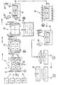
- the method according to the invention is based on a flow diagram explained in more detail below.
- the individual cores 1, 2, 3 and 4 are then in the process step I inserted into a setting gauge 5, through which the mutual assignment of cores 1, 2, 3 and 4 fixed is.
- the cores 1, 2, 3 and 4 are on their outside facing side in the usual way with core marks 6, which are now designed to be outward-looking Have contact surface, which in turn is expedient is designed so that adjacent contact surfaces 7 aligned.
- the core group combined into a unit 10 can now in a process step III via the manipulator 8.1, the clamping and holding means 8 on the gripping cam 8.2 recorded, transported and in a size bath 11 to be dipped.
- the clamping and holding means 8 can also be turned by the manipulator 8.1, so that excess size drips off after diving can. Since the frame-shaped clamping and Holding means 8 the cores summarized as a core group 1, 2, 3 and 4 holds only in the area of the core brands later when pouring the the appropriate areas of the Casting molding surfaces of the core group completely coated with sizing, with the column in particular between the individual adjacent cores 1, 2, 3 and 4 are closed by the size and thus the formation of cast burrs is avoided.
- step IV must nummore the unit 10 is fed to a drying device 16 in which the size coat is dried, for example by a combined microwave and Air drying process.
- manipulator 8.1 in a movable furnace support 12 is filed.
- the furnace support 12 has two opposite Pages cheeks 13 on with their inward clamping surfaces 14 opening upwards are inclined towards each other.
- On the clamping and holding device 8 are on both sides of the gripping cam 8.2 this outstanding clamping cams 15 arranged with one of the Provide clamping surface 14 correspondingly inclined counter surface are so that when the unit 10 is placed in the furnace support 12 the clamping and holding means 8 between the side cheeks 13 is firmly clamped. Then the manipulator 8.1 be solved and the entire arrangement in the drying facility 16 can be retracted.
- the unit 10 summarized core group from the furnace support 12 of the Manipulator 8.1 highlighted and now in the next step V in the lower box 17 or an assembly gauge a prepared mold. Only now the frame-shaped clamping and holding means 8 from the core group solved and removed. Then in the following Process step VI of the upper box 18 on the lower box 17 placed and firmly connected to it, so that subsequently the casting process can take place.
- Another advantage of the method according to the invention is in that the cycle times when casting the finished molds can be increased since those for inserting cores required time is significantly reduced.
- Another advantage of the method according to the invention is also in that greater flexibility with regard to given on customer requirements or further developments is.
- Formation of breakthroughs and then anyway must have core brands so that the core brands that are required anyway are directly related to each other touch so that tensioning with the appropriate design the core brands on the outside over a preferably frame-shaped clamping and holding means is possible.
- the method according to the invention also allows, however a common clamping and holding device two or more related core groups to a complete Summarize core sentence without the individual core groups even through an appropriate arrangement of approaches are to be brought into contact with each other.
- the procedure is therefore also possible if individual core groups with regard to their core brands none have a common clamping plane.
Landscapes
- Engineering & Computer Science (AREA)
- Mechanical Engineering (AREA)
- Molds, Cores, And Manufacturing Methods Thereof (AREA)
- Casting Devices For Molds (AREA)
- Moulds For Moulding Plastics Or The Like (AREA)
- Injection Moulding Of Plastics Or The Like (AREA)
Abstract
Description
Die Erfindung betrifft ein verfahren zum Einbringen von Kernen in eine Gießform.The invention relates to a method for introducing cores in a mold.
In der Gießereitechnik, insbesondere in der Graugußtechnik, war es bisher üblich, bei der aus wenigstens zwei Formkästen gebildete Gießform zur Herstellung von dünnwandigen Gußstücken, beispielsweise Motorblöcken, in einen der Formkästen entsprechende Kerne von Hand einzulegen. Insbesondere bei der Herstellung von Motorblöcken aus Grauguß werden in zunehmendem Maße hinsichtlich der Komplexität des Motorblocks, Gewichtseinsparungen, Maßgenauigkeiten und Oberflächenqualität höhere Anforderungen gestellt. Dies macht es erforderlich, im Kernfertigungsbereich möglichst filigrane und auch in ihrer Geometrie sehr komplexe Kerne herzustellen, die die nachfolgende mechanische Bearbeitung der Motorblöcke auf ein Minimum reduzieren. Hier hat es sich herausgestellt, daß es zweckmässig ist, den jeweils herzustellenden Motorblock so zu konzipieren, daß bisher in einer nachträglichen mechanischen Bearbeitung eingebrachte Bohrungen, Durchbrüche oder dergleichen von vornherein mit eingegossen werden. Dies macht es erforderlich, daß einander benachbarte Kerne entsprechende Ansätze aufweisen, die diese Durchbrüche in der Gießform "freihalten". Hierbei hat es sich jedoch herausgestellt, daß infolge eines nicht zu verhindernden Verschleisses und infolge nicht zu verhindernder Maßabweichungen gerade in diesem Berührungsbereich benachbarter Kerne an den herzustellenden Durchbrüchen Grate entstehen, die nach dem Ausformen des Gußstückes nachbearbeitet werden müssen.In foundry technology, especially in gray cast iron technology, It was previously common for at least two molded boxes formed mold for the production of thin-walled castings, for example engine blocks, in one of the mold boxes insert the appropriate cores by hand. Especially with the Manufacture of engine blocks from gray cast iron are increasing Dimensions regarding the complexity of the engine block, weight savings, Dimensional accuracy and surface quality made higher demands. This makes it necessary to Core manufacturing area as filigree as possible and also in your Geometry to produce very complex cores that the following mechanical processing of the engine blocks to a minimum to reduce. Here it turned out that it was useful is to design the engine block to be manufactured in such a way that so far in a subsequent mechanical processing drilled holes, breakthroughs or the like be cast in from the start. This requires that mutually adjacent cores corresponding approaches have these breakthroughs in the mold "keep clear". It has been found, however, that due to unavoidable wear and tear unavoidable dimensional deviations especially in this one Area of contact of neighboring cores on the ones to be manufactured Breakthrough burrs occur after the casting is formed have to be reworked.
In US-A-4 273 182 ist ein verfahren zur Bildung eines Kernpaketes beschrieben, bei dem die einzelnen Kernteile ohne Verwendung entsprechender Formlehren mittels formschlüssig ineinandergreifender Kernteile zu einem Kernpaket zusammengefügt werden. Um das Kernpaket wird dann mittels einer Umreifungsmaschine ein Kunststoffspannband gelegt, dessen aufeinanderliegende Enden unlösbar miteinander verbunden werden. Das so fixierte Kernpaket wird anschließend in die Gießform eingelegt. Beim Abgießen verdampft das Kunststoffband unter der Hitzeeinwirkung des geschmolzenen Metalls.US-A-4,273,182 describes a process for forming a core package described, in which the individual core parts without use corresponding gauges by means of interlocking interlocking Core parts put together to form a core package will. The core package is then strapped using a strapping machine put a plastic strap, its superimposed Ends are inextricably linked. The core package fixed in this way is then placed in the mold inserted. When pouring the plastic tape evaporates under the heat of the molten metal.
Aus EP-A-0 209 809 ist ein Verfahren bekannt, bei dem die einzelnen Kernteile in eine Fügevorrichtung eingelegt werden, die einander zugeordneten Flächen der einzelnen Kerne mit einem Kleber bestrichen werden und anschließend die einzelnen Kerne zu einem Kernpaket zusammengepreßt und über den Kleber fest miteinander zu einem Kernpaket verbunden werden. Das so gebildete Kernpaket kann dann in ein Schlichtebad getaucht und anschließend in die Gießform eingelegt werden.From EP-A-0 209 809 a method is known in which the individual core parts are placed in a joining device, the assigned areas of the individual cores with a Glue are coated and then the individual Cores pressed into a core package and over the glue firmly connected to each other to form a core package. That so The core package formed can then be immersed in a size bath and then placed in the mold.
Der Erfindung liegt nun die Aufgabe zugrunde, ein Verfahren zu schaffen, das eine Vereinfachung zum Einbringen der Kerne in eine derartige Gießform bewirkt und kostenaufwendige Nachbearbeitungen vermeidet.The invention is based on the object of a method to create a simplification to introduce the Cores in such a mold and expensive Avoids post-processing.
Diese Aufgabe wird gemäß der Erfindung dadurch gelöst, daß die einzelnen Kerne in eine Setzlehre eingebracht werden, daß die aneinandergrenzenden, eine Kerngruppe bildenden Kerne in der Setzlehre über Spann- und Haltemittel miteinander verbunden werden, daß die miteinander verbundene Kerngruppe in ein Schlichtebad getaucht und getrocknet wird und daß die getrocknete Kerngruppe in die Gießform eingesetzt und dann die Verspannung gelöst wird. Bei diesem Verfahren wird mit Vorteil ausgenutzt, daß zumindest einige, eine Kerngruppe bildende Kerne jeweils mit Kernmarken versehen sind, die so gestaltet werden können, daß sie sich einerseits gegenseitig berühren und andererseits auch die eigentliche formende Kernoberfläche überragen und entsprechende Anlageflächen bilden, so daß hier die Kerne durch ein entsprechendes, beispielsweise rahmenförmiges Spannmittel über ihre Anlageflächen gegeneinander verspannt und gegeneinander fixiert werden können und somit als eine Einheit gehandhabt werden können. Zweckmäßig ist es, wenn die einander berührenden Anlageflächen der Kerne vor dem Einlegen in die Setzlehre mit sogenanntem Grünkleber versehen werden, um den Zusammenhalt noch zu verbessern. Wird diese Kerngruppe entsprechend dem erfindungsgemäßen Verfahren in ein Schlichtebad getaucht und die Schlichte nach dem Abtropfen getrocknet, dann sind die nicht zu vermeidenden relativ dünnen Spalte im Bereich der Berührungsflächen aneinandergrenzender Einzelkerne von der Schlichte ausgefüllt, so daß hierdurch die Bildung von Graten vermieden wird. Die Kerngruppe wird dann mit Hilfe des Spann- und Haltemittels weiter transportiert und in die vorbereitete Gießform, beispielsweise einen Unterkasten, eingesetzt, so daß nach dem Lösen der Verspannung der Oberkasten aufgesetzt und die Gießvorgang in üblicher Weise durchgeführt werden kann. According to the invention, this object is achieved by that the individual cores are placed in a setting gauge, that the contiguous, forming a core group Cores in the setting gauge using clamping and holding devices be connected to each other that the connected Core group dipped in a size bath and dried and that the dried core group in the mold used and then the tension is released. With this The method is used to advantage that at least some, provide cores forming a core group with core brands are that can be designed so that they are on the one hand touch each other and on the other hand also the protrude from the actual forming core surface and corresponding Form contact surfaces so that the cores through here a corresponding, for example frame-shaped clamping means braced against each other over their contact surfaces and can be fixed against each other and thus as one Unit can be handled. It is useful if the contacting contact surfaces of the cores in front of the Insert so-called green glue into the setting gauge to improve cohesion. Becomes this core group according to the inventive method dipped in a sizing bath and the sizing after dried, then the unavoidable relatively thin gaps in the area of the contact surfaces adjacent single cores filled in by the size, so that the formation of burrs is avoided becomes. The core group is then created with the help of the clamping and Holding means transported further and into the prepared Casting mold, for example a lower case, used, so that after releasing the tension the top box is put on and performed the casting process in the usual way can be.
Das erfindungsgemäße Verfahren erlaubt es, je nach Gestaltung des herzustellenden Gußstückes eine einzelne, aus mehreren Einzelkernen zusammengesetzte Kerngruppe oder auch eine aus mehreren, eine Kernbestückung für eine Gießform bildende Kerngruppe als Kernsatz über das Spann- und Haltemittel miteinander zu verbinden und in verspanntem Zustand die einzelnen Behandlungsschritte bis zum Einlegen in die Gießform durchzuführen. Damit ist die Möglichkeit gegeben, auch sehr komplexe Kerngruppen in dieser Weise zu handhaben. Es ist auch möglich, für einzelne Kernteile vorzusehende Ansätze, die bisher noch einzeln in eine Gießform eingelegt wurden, bei der Herstellung der Kerne mit dem zugehörenden Grundkern zu verbinden, beispielsweise über eine Klebeverbindung anzukleben, so daß dieser an sich in seinem Aufbau komplizierte, aus zwei oder mehreren Teilen zusammengesetzter Einzelkern gleichwohl mit in die Kerngruppe einbezogen wird, mit dem Schlichteüberzug versehen werden kann und anschließend dann in die Gießform eingelegt werden kann. Die bisher erforderliche zusätzliche Einlegearbeit, die immer zur Bildung von Graten im Übergangsbereich zwischen dem Einzelkern und dem zugehörigen Grundkern führte, ist hierdurch vermieden, da durch den Schlichteüberzug der gesamten Kerngruppe der Ansatz zwischen dem Kernansatz und dem zugehörigen Grundkern eine Gratbildung vermeidet.The method according to the invention allows, depending on the design of the casting to be made, a single one core group composed of several individual cores or also one out of several, a core assembly for a casting mold forming core group as a core sentence about the clamping and To connect holding means with each other and in tension Condition of the individual treatment steps until insertion to perform in the mold. That is the possibility given even very complex core groups in this way to handle. It is also possible for individual core parts Approaches to be provided, which were previously individually in a mold were inserted in the manufacture of the cores with to connect the associated core, for example to glue via an adhesive connection, so that this on complicated in its structure, from two or more Share composed single core nevertheless in the Core group is included, provided with the size coating and then into the mold can be inserted. The additional required so far Inlay work that always leads to the formation of burrs in the Transition area between the single core and the associated one Basic core is avoided, because by the Sizing the entire core group the approach between the core approach and the associated basic core a ridge formation avoids.
Das erfindungsgemäße Verfahren wird anhand eines Fließbildes nachstehend näher erläutert.The method according to the invention is based on a flow diagram explained in more detail below.
Wie aus der Zeichnung ersichtlich, werden in vier Kernformstationen vier einzelne, zur Herstellung eines Gußstückes erforderliche Kerne geformt und in üblicher Weise verfestigt.As can be seen from the drawing, there are four core forming stations four single, for the production of a casting required cores formed and solidified in the usual way.
Die Einzelkerne 1, 2, 3 und 4 werden dann im Verfahrensschritt
I in eine Setzlehre 5 eingelegt, durch die die
gegenseitige Zuordnung der Kerne 1, 2, 3 und 4 fixiert
ist. Die Kerne 1, 2, 3 und 4 sind auf ihrer nach außen
weisenden Seite in üblicher Weise mit Kernmarken 6 versehen,
die nun so gestaltet sind, daß sie eine nach außenweisende
Anlagefläche aufweisen, die zweckmäßigerweise ihrerseits
so gestaltet ist, daß einander benachbarte Anlageflächen
7 miteinander fluchten.The
Die eine Kerngruppe bildenden, in die Setzlehre 5 eingelegten
Einzelkerne 1, 2, 3 und 4 werden nunmehr mit einem
beispielsweise rahmenförmig ausgebildeten Spann- und Haltemittel
8 fest miteinander verspannt, wobei die gegeneinander
gerichteten Ansätze 9 an den einzelnen Kernen 1, 2, 3 und
4, die je nach Gestaltung des zu erzeugenden Gußstückes
entweder zur Herstellung von Durchbrüchen in entsprechenden
Wandungsteilen des Gußstückes dienen oder aber die ihrerseits
als Kernmarken ausgebildet sind, fest aneinander
gedrückt werden. Die Kerne können an ihren einander zugekehrten
Anlageflächen 9.1 mit einem sogenannten Grünkleber
versehen sein, so daß in diesem Bereich durch eine Verklebung
die Fixierung noch erhöht wird. Bei entsprechender
Gestaltung der einzelnen Kerne 1, 2, 3 und 4 ist somit
die Möglichkeit gegeben, die einzelnen Kerne über das Spann- und
Haltemittel 8 zu einer handhabbaren Einheit 10 zusammenzufassen,
wie dies für den anschliessenden Verfahrensschritt
II dargestellt ist. Die Verspannung des Spann- und
Haltemittels 8 kann nun bei entsprechender Gestaltung
durch das Mittel selbst oder aber über einen greifenden
und spannenden Manipulator 8.1 erfolgen.Those forming a core group, inserted into the
Die zu einer Einheit 10 zusammengefaßte Kerngruppe kann
nunmehr in einem Verfahrensschritt III über den Manipulator
8.1, der das Spann- und Haltemittel 8 am Greifnocken
8.2 erfaßt, weitertransportiert werden und in ein Schlichtebad
11 getaucht werden. Hierbei kann das Spann- und Haltemittel
8 durch den Manipulator 8.1 auch gewendet werden,
so daß nach dem Tauchen überschüssige Schlichte abtropfen
kann. Da das beispielsweise rahmenförmig ausgebildete Spann- und
Haltemittel 8 die als Kerngruppe zusammengefaßten Kerne
1, 2, 3 und 4 nur im Bereich der Kernmarken hält, sind
später beim Gießen die die entsprechenden Bereiche des
Gußstückes formenden Oberflächen der Kerngruppe vollständig
mit Schlichte überzogen, wobei insbesondere die Spalte
zwischen den einzelnen aneinandergrenzenden Kernen 1, 2,
3 und 4 durch die Schlichte verschlossen sind und damit
die Bildung von Gußgraten vermieden wird.The core group combined into a
In dem anschließenden Verfahrensschritt IV muß nummehr
die Einheit 10 einer Trocknungseinrichtung 16 zugeführt
werden, in der der Schlichteüberzug abgetrocknet wird,
beispielsweise durch eine kombiniertes Mikrowellen- und
Lufttrockungsverfahren.In the subsequent process step IV must nummore
the
Um die Einheit durch die Trocknungseinrichtung zu führen,
wird diese vom Manipulator 8.1 in einem bewegbaren Ofenträger
12 abgelegt. Der Ofenträger 12 weist auf zwei gegenüberliegenden
Seiten Spannwangen 13 auf, die mit ihren
nach innen gerichteten Spannflächen 14 nach oben öffnend
gegeneinander geneigt sind. Am Spann- und Haltemittel 8
sind zu beiden Seiten des Greifnockens 8.2 diesen jeweils
überragende Spannocken 15 angeordnet, die mit einer der
Spannfläche 14 entsprechend geneigten Gegenfläche versehen
sind, so daß beim Absetzen der Einheit 10 in den Ofenträger
12 das Spann- und Haltemittel 8 zwischen den Seitenwangen
13 fest eingeklemmt wird. Danach kann der Manipulator 8.1
gelöst werden und die gesamte Anordnung in die Trocknungseinrichtung
16 eingefahren werden.To guide the unit through the dryer,
is manipulator 8.1 in a
Nach Abschluß der Trocknung wird die in der Einheit 10
zusammengefaßte Kerngruppe aus dem Ofenträger 12 von dem
Manipulator 8.1 herausgehoben und nunmehr im nächsten Verfahrensschritt
V in den Unterkasten 17 oder eine Aufbaulehre
einer vorbereiteten Gießform eingelegt. Erst jetzt wird
das rahmenförmige Spann- und Haltemittel 8 von der Kerngruppe
gelöst und entfernt. Anschließend wird im folgenden
Verfahrensschritt VI der Oberkasten 18 auf den Unterkasten
17 aufgesetzt und mit diesem fest verbunden, so daß anschließend
der Gießvorgang erfolgen kann. After drying is complete, the
Aus der vorstehenden Beschreibung des Verfahrensablaufes für ein schematisches Ausführungsbeispiel mit einer aus vier Einzelkernen zusammengesetzten Kerngruppe ist ersichtlich, daß auch sehr komplexe Gußstücke nach dem erfindungsgemäßen Verfahren erstellt werden können. So ist es durchaus möglich, mehrere, eine Kernbestückung für eine Gießform bildenden Kerngruppen, die von der Konzeption des Gußstückes untereinander nicht in Verbindung stehen sollen, bei einer entsprechenden Ausgestaltung des Spann- und Haltemittels als vollständigen Kernsatz miteinander zu verbinden und in der nachfolgenden Behandlung, d. h. dem Überziehen mit einer Schlichte und dem anschließenden Trocknen bis zum Einlegen in die Gießform zusammenzuhalten.From the above description of the procedure for a schematic embodiment with one four individual cores composed core group can be seen that even very complex castings according to the invention Procedures can be created. It is quite so possible, several, one core for one mold forming core groups, from the design of the casting should not be connected to one another corresponding design of the clamping and holding means to combine as a complete core sentence and in the subsequent treatment, d. H. covering with a size and then drying until Place in the mold to hold together.
Es ist ohne weiteres ersichtlich, daß durch das Zusammenfassen von einzelnen Kernen zu Kerngruppen und/oder das Zusammenfassen von Kerngruppen zu vollständigen Kernsätzen, der Aufwand für den Transport und die einzelnen Arbeitsschritte Tauchen, Trocknen und Einlegen der Kerne in die Gießform minimiert werden. Soweit die Einzelkerne einander zugeordnete Ansätze aufweisen, die zur Erstellung von Durchbrüchen im fertigen Gußstück vorgesehen sind, durch den Schlichteüberzug der vollständigen Kerngruppe bzw. des Kernsatzes verschlossen werden, reduzieren sich die nachfolgenden Putzarbeiten, insbesondere das Entgraten am fertigen Gußstück erheblich. Der weitere Vorteil des erfindungsgemäßen Verfahrens besteht darin, daß durch das Einsetzen einer vollständigen Kerngruppe und/oder eines vollständigen Kernsatzes in die Gießform die Maßhaltigkeit verbessert und damit der Ausschuß minimiert wird.It is readily apparent that by summarizing from individual cores to core groups and / or that Grouping of core groups into complete core sentences, the effort for transport and the individual work steps Dip, dry and insert the cores into the Mold to be minimized. So much for the individual cores have associated approaches to creating breakthroughs are provided in the finished casting, by the Finishing of the complete core group or the Core sentence are closed, the following are reduced Cleaning work, especially deburring on the finished Casting considerably. The further advantage of the invention Procedure is that by insertion a complete core group and / or a complete Core set in the mold improves dimensional accuracy and so that the committee is minimized.
Ein weiterer Vorteil des erfindungsgemäßen Verfahrens besteht darin, daß die Taktzeiten beim Abguß der fertigen Formen erhöht werden können, da die für das Einlegen von Kerne benötigte Zeit erheblich reduziert ist. Another advantage of the method according to the invention is in that the cycle times when casting the finished molds can be increased since those for inserting cores required time is significantly reduced.
Ein weiterer Vorteil des erfindungsgemäßen Verfahrens besteht außerdem darin, daß eine höhere Flexibilität in bezug auf Kundenanforderungen oder Weiterentwicklungen gegeben ist. Hier ist es lediglich erforderlich, bei der Gestaltung der Kerne dafür Sorge zu tragen, daß einander benachbarte Kerne, auch wenn diese zwischen sich keine Ansätze zur Bildung von Durchbrüchen aufweisen und die dann ohnehin über Kernmarken verfügen müssen, so gestaltet werden, daß die ohnehin erforderlichen Kernmarken einander unmittelbar berühren, so daß ein Verspannen bei entsprechender Gestaltung der Kernmarken an der Außenseite über ein vorzugsweise rahmenförmiges Spann- und Haltemittel möglich ist.Another advantage of the method according to the invention is also in that greater flexibility with regard to given on customer requirements or further developments is. Here it is only necessary when designing of the cores to ensure that neighboring ones Cores, even if there are no approaches between them Formation of breakthroughs and then anyway must have core brands so that the core brands that are required anyway are directly related to each other touch so that tensioning with the appropriate design the core brands on the outside over a preferably frame-shaped clamping and holding means is possible.
Das erfindungsgemäße Verfahren erlaubt es aber auch, in einem gemeinsamen Spann- und Haltemittel zwei oder mehrere einander zugehörige Kerngruppen zu einem vollständigen Kernsatz zusammenzufassen, ohne daß die einzelnen Kerngruppen selbst über eine entsprechende Anordnung von Ansätzen miteinander in Berührung zu bringen sind. Das erfindungsgemäße Verfahren ist daher auch dann möglich, wenn einzelne Kerngruppen hinsichtlich ihrer Kernmarken keine gemeinsame Spannebene aufweisen. Hier ist es dann möglich, in einem Hauptrahmen die einzelnen Kerngruppen mit gesonderten Spann- und Haltemitteln miteinander zu verspannen und für die nachfolgenden Verfahrensschritte bis zum Einlegen in die Gießform zu handhaben.The method according to the invention also allows, however a common clamping and holding device two or more related core groups to a complete Summarize core sentence without the individual core groups even through an appropriate arrangement of approaches are to be brought into contact with each other. The invention The procedure is therefore also possible if individual core groups with regard to their core brands none have a common clamping plane. Here it is possible in a main frame the individual core groups with separate Clamping and holding devices together and for the subsequent process steps up to Insert into the mold to handle.
Claims (3)
- A method for introducing cores into a casting mould, characterised in that the individual cores (1, 2, 3, 4) are introduced into a template (5), that the cores (1, 2, 3, 4) which adjoin one another and form a core group are joined together in the template (5) by means of a bracing and holding means (8), that the interconnected core group is dipped into a founder's black bath (11) and dried, and that the dried core group is inserted into the casting mould (17, 18) and then the bracing means is released.
- A method according to Claim 1, characterised in that a plurality of core groups which form core inserts for a casting mould are joined together as a core set by means of a bracing and holding means (8), are treated and are inserted into the casting mould.
- A method according to Claim 1 or 2, characterised in that the contact surfaces (9.1) of the cores (1, 2, 3, 4) which contact one another are provided with an adhesive before insertion into the template (5).
Applications Claiming Priority (3)
| Application Number | Priority Date | Filing Date | Title |
|---|---|---|---|
| DE19540023 | 1995-10-27 | ||
| DE19540023A DE19540023A1 (en) | 1995-10-27 | 1995-10-27 | Process for inserting cores into a mold |
| PCT/EP1996/002943 WO1997016271A1 (en) | 1995-10-27 | 1996-07-04 | Process for introducing cores into a casting mould |
Publications (2)
| Publication Number | Publication Date |
|---|---|
| EP0802839A1 EP0802839A1 (en) | 1997-10-29 |
| EP0802839B1 true EP0802839B1 (en) | 1998-12-02 |
Family
ID=7775929
Family Applications (1)
| Application Number | Title | Priority Date | Filing Date |
|---|---|---|---|
| EP96924883A Expired - Lifetime EP0802839B1 (en) | 1995-10-27 | 1996-07-04 | Process for introducing cores into a casting mould |
Country Status (9)
| Country | Link |
|---|---|
| US (1) | US6003588A (en) |
| EP (1) | EP0802839B1 (en) |
| JP (1) | JP3894569B2 (en) |
| CN (1) | CN1131746C (en) |
| AT (1) | ATE173965T1 (en) |
| DE (2) | DE19540023A1 (en) |
| DK (1) | DK0802839T3 (en) |
| ES (1) | ES2127647T3 (en) |
| WO (1) | WO1997016271A1 (en) |
Families Citing this family (6)
| Publication number | Priority date | Publication date | Assignee | Title |
|---|---|---|---|---|
| US6527039B2 (en) * | 2001-06-11 | 2003-03-04 | General Motors Corporation | Casting of engine blocks |
| US6533020B2 (en) * | 2001-06-11 | 2003-03-18 | General Motors Corporation | Casting of engine blocks |
| US6682315B2 (en) * | 2001-11-28 | 2004-01-27 | Caterpillar Inc | Axial piston pump barrel with a cast high pressure collection cavity |
| US20040159985A1 (en) * | 2003-02-18 | 2004-08-19 | Altoonian Mark A. | Method for making ceramic setter |
| CN107598132B (en) * | 2017-09-28 | 2023-07-21 | 苏州明志科技股份有限公司 | Glue injection workbench for sand core assembly |
| CN116441490A (en) * | 2023-03-30 | 2023-07-18 | 潍柴动力股份有限公司 | Casting device and core setting method |
Family Cites Families (7)
| Publication number | Priority date | Publication date | Assignee | Title |
|---|---|---|---|---|
| US4273182A (en) * | 1979-12-07 | 1981-06-16 | Ford Motor Company | Core assembly and the method of making and using such assembly |
| JPS6213240A (en) * | 1985-07-10 | 1987-01-22 | Kiriyuu Kikai Kk | Method for assembling core and assembled core |
| DE3526265A1 (en) * | 1985-07-23 | 1987-02-05 | Hottinger Adolf Giesserei | CORE OR MASK PACKING MACHINE |
| JPS62230454A (en) * | 1986-03-31 | 1987-10-09 | Mazda Motor Corp | Casting mold for manihold |
| DE3618703A1 (en) * | 1986-06-04 | 1987-12-10 | Bruehl Eisenwerk | METHOD FOR PRODUCING CORE FOR FOUNDRY PURPOSES AND DEVICE FOR IMPLEMENTING THE METHOD |
| JPS6464740A (en) * | 1987-04-14 | 1989-03-10 | Northrop Corp | Built-up data model system |
| DE4322181A1 (en) * | 1993-06-29 | 1995-01-12 | Hottinger Adolf Masch | Device and method for gripping a foundry core, in particular a sole core |
-
1995
- 1995-10-27 DE DE19540023A patent/DE19540023A1/en not_active Withdrawn
-
1996
- 1996-07-04 WO PCT/EP1996/002943 patent/WO1997016271A1/en not_active Ceased
- 1996-07-04 EP EP96924883A patent/EP0802839B1/en not_active Expired - Lifetime
- 1996-07-04 AT AT96924883T patent/ATE173965T1/en not_active IP Right Cessation
- 1996-07-04 ES ES96924883T patent/ES2127647T3/en not_active Expired - Lifetime
- 1996-07-04 JP JP52976696A patent/JP3894569B2/en not_active Expired - Fee Related
- 1996-07-04 CN CN96191295A patent/CN1131746C/en not_active Expired - Fee Related
- 1996-07-04 US US08/836,149 patent/US6003588A/en not_active Expired - Fee Related
- 1996-07-04 DK DK96924883T patent/DK0802839T3/en active
- 1996-07-04 DE DE59600907T patent/DE59600907D1/en not_active Expired - Fee Related
Also Published As
| Publication number | Publication date |
|---|---|
| WO1997016271A1 (en) | 1997-05-09 |
| ES2127647T3 (en) | 1999-04-16 |
| US6003588A (en) | 1999-12-21 |
| JP3894569B2 (en) | 2007-03-22 |
| DK0802839T3 (en) | 1999-08-16 |
| DE59600907D1 (en) | 1999-01-14 |
| CN1131746C (en) | 2003-12-24 |
| JPH10511315A (en) | 1998-11-04 |
| CN1166801A (en) | 1997-12-03 |
| ATE173965T1 (en) | 1998-12-15 |
| DE19540023A1 (en) | 1997-04-30 |
| EP0802839A1 (en) | 1997-10-29 |
Similar Documents
| Publication | Publication Date | Title |
|---|---|---|
| DE69603826T2 (en) | Method and device for producing aluminum alloy castings | |
| DE3829402C2 (en) | ||
| EP0802839B1 (en) | Process for introducing cores into a casting mould | |
| DE1913077A1 (en) | Composite mold and method of making it | |
| DE202018102896U1 (en) | casting system | |
| EP0268656B1 (en) | Process for producing moulds and mould elements for casting purposes, in particular for producing cores, and installation for performing the process | |
| EP0878258B1 (en) | Casting plant | |
| DE2804067A1 (en) | METHOD OF MANUFACTURING ASSEMBLED PARTS | |
| DE3624554A1 (en) | System for the production of a core assembly | |
| DE112014004748T5 (en) | Injection molding and assembly apparatus and method for casting and assembling a plurality of two different castings | |
| DE60011307T2 (en) | METHOD AND DEVICE FOR THE STEP-BY-STEP PROCESSING OF CHILLERS IN A CASTING PLANT | |
| EP0731741B1 (en) | Installation and method for producing ready-to-use casting shells or core assemblies | |
| DE4341122C2 (en) | Device and method for producing ready-to-cast masks or core packages | |
| WO2005014203A2 (en) | Device for the production of core assemblies | |
| EP0704261A1 (en) | Mould with core print and casting piece with closure for core opening | |
| EP3322547B1 (en) | Method for producing a casting core, and a casting core | |
| DE102008009092B3 (en) | Casting process to manufacture complex cast form e.g. automotive turbo charger components using soluble binding agent and soluble core insert | |
| DE4006031C2 (en) | Device for producing cores in a two-part core box | |
| DE3445732A1 (en) | Method for the production of a mould core to be placed in a casting mould | |
| DE3733128C1 (en) | Method for keeping core exit surfaces of ceramic hollow bodies provided with sand cores free from core sand | |
| DE3212352A1 (en) | Displacement casting machine | |
| DE1932971A1 (en) | Ceramic compound mould | |
| DE102014018175A1 (en) | Process for the production of casting molds for the production of castings, in particular of metal, such as cast iron, casting mold produced therefrom, device for carrying out the process, process for the production of castings, castings produced therefrom, and equipment for the production of castings | |
| DE9318597U1 (en) | Device for the production of ready-to-cast masks or core packages | |
| DE3148460C1 (en) | Apparatus for gumming and straightening foundry moulding shells and cores |
Legal Events
| Date | Code | Title | Description |
|---|---|---|---|
| PUAI | Public reference made under article 153(3) epc to a published international application that has entered the european phase |
Free format text: ORIGINAL CODE: 0009012 |
|
| 17P | Request for examination filed |
Effective date: 19970417 |
|
| AK | Designated contracting states |
Kind code of ref document: A1 Designated state(s): AT DE DK ES FR GB IE IT SE |
|
| 17Q | First examination report despatched |
Effective date: 19971117 |
|
| GRAG | Despatch of communication of intention to grant |
Free format text: ORIGINAL CODE: EPIDOS AGRA |
|
| GRAG | Despatch of communication of intention to grant |
Free format text: ORIGINAL CODE: EPIDOS AGRA |
|
| GRAH | Despatch of communication of intention to grant a patent |
Free format text: ORIGINAL CODE: EPIDOS IGRA |
|
| GRAH | Despatch of communication of intention to grant a patent |
Free format text: ORIGINAL CODE: EPIDOS IGRA |
|
| GRAA | (expected) grant |
Free format text: ORIGINAL CODE: 0009210 |
|
| AK | Designated contracting states |
Kind code of ref document: B1 Designated state(s): AT DE DK ES FR GB IE IT SE |
|
| REF | Corresponds to: |
Ref document number: 173965 Country of ref document: AT Date of ref document: 19981215 Kind code of ref document: T |
|
| REF | Corresponds to: |
Ref document number: 59600907 Country of ref document: DE Date of ref document: 19990114 |
|
| REG | Reference to a national code |
Ref country code: IE Ref legal event code: FG4D Free format text: GERMAN |
|
| ET | Fr: translation filed | ||
| ITF | It: translation for a ep patent filed | ||
| GBT | Gb: translation of ep patent filed (gb section 77(6)(a)/1977) |
Effective date: 19990225 |
|
| REG | Reference to a national code |
Ref country code: ES Ref legal event code: FG2A Ref document number: 2127647 Country of ref document: ES Kind code of ref document: T3 |
|
| REG | Reference to a national code |
Ref country code: DK Ref legal event code: T3 |
|
| PLBE | No opposition filed within time limit |
Free format text: ORIGINAL CODE: 0009261 |
|
| STAA | Information on the status of an ep patent application or granted ep patent |
Free format text: STATUS: NO OPPOSITION FILED WITHIN TIME LIMIT |
|
| 26N | No opposition filed | ||
| REG | Reference to a national code |
Ref country code: GB Ref legal event code: IF02 |
|
| PGFP | Annual fee paid to national office [announced via postgrant information from national office to epo] |
Ref country code: DK Payment date: 20020722 Year of fee payment: 7 |
|
| PGFP | Annual fee paid to national office [announced via postgrant information from national office to epo] |
Ref country code: IE Payment date: 20020730 Year of fee payment: 7 |
|
| PG25 | Lapsed in a contracting state [announced via postgrant information from national office to epo] |
Ref country code: IE Free format text: LAPSE BECAUSE OF NON-PAYMENT OF DUE FEES Effective date: 20030704 |
|
| PG25 | Lapsed in a contracting state [announced via postgrant information from national office to epo] |
Ref country code: DK Free format text: LAPSE BECAUSE OF NON-PAYMENT OF DUE FEES Effective date: 20030731 |
|
| REG | Reference to a national code |
Ref country code: DK Ref legal event code: EBP |
|
| REG | Reference to a national code |
Ref country code: IE Ref legal event code: MM4A |
|
| PGFP | Annual fee paid to national office [announced via postgrant information from national office to epo] |
Ref country code: ES Payment date: 20080723 Year of fee payment: 13 Ref country code: DE Payment date: 20080722 Year of fee payment: 13 |
|
| PGFP | Annual fee paid to national office [announced via postgrant information from national office to epo] |
Ref country code: IT Payment date: 20080726 Year of fee payment: 13 Ref country code: FR Payment date: 20080718 Year of fee payment: 13 Ref country code: AT Payment date: 20080722 Year of fee payment: 13 |
|
| PGFP | Annual fee paid to national office [announced via postgrant information from national office to epo] |
Ref country code: GB Payment date: 20080723 Year of fee payment: 13 |
|
| PGFP | Annual fee paid to national office [announced via postgrant information from national office to epo] |
Ref country code: SE Payment date: 20080724 Year of fee payment: 13 |
|
| EUG | Se: european patent has lapsed | ||
| GBPC | Gb: european patent ceased through non-payment of renewal fee |
Effective date: 20090704 |
|
| REG | Reference to a national code |
Ref country code: FR Ref legal event code: ST Effective date: 20100331 |
|
| PG25 | Lapsed in a contracting state [announced via postgrant information from national office to epo] |
Ref country code: FR Free format text: LAPSE BECAUSE OF NON-PAYMENT OF DUE FEES Effective date: 20090731 |
|
| PG25 | Lapsed in a contracting state [announced via postgrant information from national office to epo] |
Ref country code: GB Free format text: LAPSE BECAUSE OF NON-PAYMENT OF DUE FEES Effective date: 20090704 |
|
| PG25 | Lapsed in a contracting state [announced via postgrant information from national office to epo] |
Ref country code: DE Free format text: LAPSE BECAUSE OF NON-PAYMENT OF DUE FEES Effective date: 20100202 Ref country code: AT Free format text: LAPSE BECAUSE OF NON-PAYMENT OF DUE FEES Effective date: 20090704 |
|
| REG | Reference to a national code |
Ref country code: ES Ref legal event code: FD2A Effective date: 20090706 |
|
| PG25 | Lapsed in a contracting state [announced via postgrant information from national office to epo] |
Ref country code: ES Free format text: LAPSE BECAUSE OF NON-PAYMENT OF DUE FEES Effective date: 20090706 |
|
| PG25 | Lapsed in a contracting state [announced via postgrant information from national office to epo] |
Ref country code: IT Free format text: LAPSE BECAUSE OF NON-PAYMENT OF DUE FEES Effective date: 20090704 |
|
| PG25 | Lapsed in a contracting state [announced via postgrant information from national office to epo] |
Ref country code: SE Free format text: LAPSE BECAUSE OF NON-PAYMENT OF DUE FEES Effective date: 20090705 |