EP0802549A2 - Motor antrieb für elektrische Schalter - Google Patents
Motor antrieb für elektrische Schalter Download PDFInfo
- Publication number
- EP0802549A2 EP0802549A2 EP97105637A EP97105637A EP0802549A2 EP 0802549 A2 EP0802549 A2 EP 0802549A2 EP 97105637 A EP97105637 A EP 97105637A EP 97105637 A EP97105637 A EP 97105637A EP 0802549 A2 EP0802549 A2 EP 0802549A2
- Authority
- EP
- European Patent Office
- Prior art keywords
- switch
- handle
- motor
- actuator
- motor operator
- Prior art date
- Legal status (The legal status is an assumption and is not a legal conclusion. Google has not performed a legal analysis and makes no representation as to the accuracy of the status listed.)
- Withdrawn
Links
- 238000010586 diagram Methods 0.000 description 2
- 238000009434 installation Methods 0.000 description 1
- 230000003993 interaction Effects 0.000 description 1
- 239000000463 material Substances 0.000 description 1
- 230000004048 modification Effects 0.000 description 1
- 238000012986 modification Methods 0.000 description 1
- 230000007935 neutral effect Effects 0.000 description 1
- 230000000717 retained effect Effects 0.000 description 1
- 239000007858 starting material Substances 0.000 description 1
- 210000001364 upper extremity Anatomy 0.000 description 1
- 230000000007 visual effect Effects 0.000 description 1
Images

Classifications
-
- H—ELECTRICITY
- H01—ELECTRIC ELEMENTS
- H01H—ELECTRIC SWITCHES; RELAYS; SELECTORS; EMERGENCY PROTECTIVE DEVICES
- H01H71/00—Details of the protective switches or relays covered by groups H01H73/00 - H01H83/00
- H01H71/10—Operating or release mechanisms
- H01H71/66—Power reset mechanisms
- H01H71/70—Power reset mechanisms actuated by electric motor
-
- H—ELECTRICITY
- H01—ELECTRIC ELEMENTS
- H01H—ELECTRIC SWITCHES; RELAYS; SELECTORS; EMERGENCY PROTECTIVE DEVICES
- H01H71/00—Details of the protective switches or relays covered by groups H01H73/00 - H01H83/00
- H01H71/02—Housings; Casings; Bases; Mountings
- H01H71/0207—Mounting or assembling the different parts of the circuit breaker
- H01H2071/0242—Assembling parts of a circuit breaker by using snap mounting techniques
-
- H—ELECTRICITY
- H01—ELECTRIC ELEMENTS
- H01H—ELECTRIC SWITCHES; RELAYS; SELECTORS; EMERGENCY PROTECTIVE DEVICES
- H01H71/00—Details of the protective switches or relays covered by groups H01H73/00 - H01H83/00
- H01H71/10—Operating or release mechanisms
- H01H71/66—Power reset mechanisms
- H01H2071/665—Power reset mechanisms the reset mechanism operating directly on the normal manual operator, e.g. electromagnet pushes manual release lever back into "ON" position
-
- H—ELECTRICITY
- H01—ELECTRIC ELEMENTS
- H01H—ELECTRIC SWITCHES; RELAYS; SELECTORS; EMERGENCY PROTECTIVE DEVICES
- H01H3/00—Mechanisms for operating contacts
- H01H3/22—Power arrangements internal to the switch for operating the driving mechanism
- H01H3/26—Power arrangements internal to the switch for operating the driving mechanism using dynamo-electric motor
- H01H3/264—Power arrangements internal to the switch for operating the driving mechanism using dynamo-electric motor using a travelling nut mechanism
-
- H—ELECTRICITY
- H01—ELECTRIC ELEMENTS
- H01H—ELECTRIC SWITCHES; RELAYS; SELECTORS; EMERGENCY PROTECTIVE DEVICES
- H01H9/00—Details of switching devices, not covered by groups H01H1/00 - H01H7/00
- H01H9/20—Interlocking, locking, or latching mechanisms
- H01H9/28—Interlocking, locking, or latching mechanisms for locking switch parts by a key or equivalent removable member
- H01H9/281—Interlocking, locking, or latching mechanisms for locking switch parts by a key or equivalent removable member making use of a padlock
- H01H9/282—Interlocking, locking, or latching mechanisms for locking switch parts by a key or equivalent removable member making use of a padlock and a separate part mounted or mountable on the switch assembly and movable between an unlocking position and a locking position where it can be secured by the padlock
Definitions
- This invention relates to motor driven apparatus for operating the handle of electrical switches, especially circuit breakers and contactors. More particularly, it relates to a motor operator that can be easily swung aside for manual operation of the switch handle, and which has a single power switch for energizing the motor and determining direction of handle travel.
- Switches particularly switches such as circuit breakers and contactors
- Many such devices have an actuator forming a slot that engages the switch handle.
- the actuator is mounted on a threaded shaft rotated by an electric motor. It is common for the mounting of the motor operator to the switch to he such that once the motor operator is in place, the switch handle is not accessible for manual operation. In these installations, it is common for manual operation to be provided by a crank which rotates the threaded shaft in place of motor operation.
- a motor operator assembly having a motor operator unit hinged at one end to a mounting bracket secured to the switch adjacent to the switch handle so that the motor operator unit may he readily rotated between an operative position in which it engages the switch handle for electrical operation of the switch, and a manual position in which the motor operator is rotated clear of the handle thereby providing direct access to the switch handle for manual operation.
- Latch means comprising a first latch member on the mounting bracket and second latch means mounted on a free end of the motor operator unit opposite the hinged end, releasably engage as the motor operator unit is rotated to the operative position. This makes the line of engagement and disengagement of the latching means transverse to movement of the actuator within the motor operator unit which engages the switch handle. Hence, the latching forces can be relatively light as the reaction to the movement of the switch handle does not tend to release the latch.
- the motor operator unit includes an actuator which reciprocates the switch handle in the handle slot and toggles a single power switch to reverse direction of the electric motor driving the actuator after the switch handle has been driven to the ends of the handle slot.
- This single switch provides both direction control and shut-off for the motor following handle operation.
- the actuator has a compliant section forming a slot which engages the switch handle and allows the actuator to overtravel after the switch handle is operated to ensure switch operation before the power switch is toggled.
- the motor operator unit includes an interlock switch which prevents energization of the motor until the unit is fully rotated to the operative position, and the actuator is configured to engage the handle to prevent rotation to the operative position and actuation of the interlock switch if the position of the actuator does not correspond to that of the switch handle.
- An interlock member selectively mechanically locks the motor operator unit in the operative position, but with the interlock switch opened to prevent both automatic and manual operation of the switch.
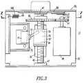
- the invention is directed to a motor operator assembly 1 used to operate a switch 3 such as the circuit breaker shown having a switch handle 5 which reciprocates in an elongated handle slot 7 in a face 9 of the switch. While the illustrative switch 3 is a circuit breaker, it will be appreciated that the motor operator 1 is suitable for use with other types of electrical switches including contactors and motor starters.
- the motor operator assembly 1 includes a motor operator unit 11 and a mounting bracket 13 for securing the motor operator unit 11 to the switch 3 for operation of the switch handle 5.
- the mounting bracket 13 is a planar member 15 having opposite edges turned down to form legs 17.
- the bracket 13 is secured to the face 9 of the circuit breaker by fasteners 19 extending through mounting flanges 21 projecting laterally from the legs 17.
- the mounting bracket 13 is secured to the electrical switch 3 with a slot 23 in the planner member 15 aligned with the handle slot 7 and with the switch handle 5 projecting through the slot 23.
- the motor operator unit 11 includes a U-shaped carriage 25 fabricated from sheet material with hinge members 27 punched out of one end 29. These hinge members 27 engage a pivot pin 31 retained by punched out section 33 in one end of the mounting bracket 13 so that the motor operator unit 11 is pivotally connected to the mounting bracket 13.
- the base of the carriage 25 has an elongated slot 35 which registers with the slot 23 in the mounting bracket 13 when the carriage 25 is rotated to an operative or closed position in which the carriage rests flat on the mounting bracket 13.
- the motor operator unit is maintained in the operative or closed position by a latching mechanism 37, preferably a ball-snap latch, including a first, male latch member 39 mounted on the mounting bracket 13 and a second, female latch member 41 mounted on the carriage at a free end 43.
- This latch mechanism 37 allows the motor operator unit 11 to be easily secured in the operative position upon closing, and can be easily pulled open to allow manual access to the switch. It will be seen that the reaction forces within the motor operator unit 11 to movement of the switch are transverse to the relative movement of the latch members 39 and 41, so that operation of the motor operator unit does not tend to open the latch mechanism.
- the motor operator unit 11 includes, in addition to the carriage 25, a threaded shaft 45 journaled in bearings 47 in the legs of the carriage 25.
- the threaded shaft 45 is rotated by an electric motor 49, mounted on the carriage 25, through a pair of gears 51 on the motor shaft 53 and gears 55 on the threaded shaft.
- the threaded shaft 45 is mounted above and parallel to the slot 35 in the carriage 25, and therefore, to the handle slot 7 in the switch 3.
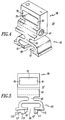
- An actuator 57 as best seen in Figures 4 and 5, has a body section 59 having a threaded bore 61 which engages the threaded shaft 45.
- the actuator 57 has a compliant section 63 cantilevered from the body 59 by extension or support 65.
- the compliant section 63 has a pair of confronting fingers 67 which form between them a slot 69.
- the actuator 57 not only operates the switch handle 5, but also serves as the actuator for a single power switch 71, (see Figures 3 and 8).
- This power switch 71 is mounted on a bracket 73 secured to the carriage 25.
- the main body 59 of the actuator 57 has an elongated recess 75 in which the operating lever 77 of the power switch 71 is received.
- the recess 75 is sized and has end walls 79 and 81 spaced apart such that the switch 71 is toggled as the actuator reaches the ends of its reciprocal travel.
- the single power switch 71 determines the direction of movement of the actuator 57 and also terminates motor power at the end of each stroke.
- the actuator 57 In order to ensure that the switch handle 5 is positively operated before terminating motor operation, the actuator 57 must overtravel at each end of its reciprocal path before toggling the single power switch 71. This is made possible by the compliant section 63 of the actuator which engages the switch handle 5. When the switch handle 5 reaches the end of its travel in the handle slot 7, the cantilevered support 65 bends, and the fingers 67 deform to allow the actuator to continue its travel until the power switch 71 is toggled.
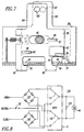
- the motor operator 11 further includes an electrical interlock switch 83 which controls operation of the motor 49 (see Figures 7 and 8).
- the interlock switch 83 is mounted on a locking plate 85 which is slidably mounted to the inside of the front leg 25L of the carriage 25 by guide pins 87 mounted on the leg 25L which engage slots 89 in the locking plate.
- the interlock switch 83 With the motor operator unit 11 in the operative position so that the actuator 57 engages the switch handle 5, the interlock switch 83 is closed by a cam 91 punched out of the planner member 15 of the bracket (see Figure 1) and extending through an opening 93 punched in the base of the carriage 25. This cam 91 engages the operating lever 84 of the switch 83.
- closing of the interlock switch 83 enables energization of the motor 49.
- the locking plate 85 also performs a mechanical lockout function preventing operation of the electrical switch 3.
- the locking plate 85 has a pair of depending hooks 95 which project through openings 97 in the carriage 25.
- the hooks 95 project through openings 99 in the front of the planner member 15 of the mounting bracket 13.
- the interlock switch 83 is actuated by the cam 91 so that the switch handle 5 can be electrically operated by the motor operator unit.
- the locking plate 85 is biased to this unlocked position by a spring 100.
- the locking plate 85 is pushed laterally so that the hooks 95 engage the bottom of the planner member 15 of the mounting bracket 13. This also moves the interlock switch 83 laterally so that it is no longer actuated by the cam 91. Thus, the switch handle 5 cannot be electrically operated by the motor operator unit 11.
- the locking plate has an extension 101 at its upper end with an aperture 103. With the locking plate 85 in the lockout position, the extension 101 on the locking plate is aligned with a hand grip extension 105 on the free end 43 of the carriage 25 so that the aperture 103 is in register with an aperture 107 in the hand grip 105 (see Figure 1).
- a padlock 106 (see Figure 2) can be inserted through the apertures 103 and 107 to mechanically lock the locking plate 85 in the lockout position. With the locking plate padlocked in the lockout position, the switch handle cannot be electrically operated since the interlock switch 83 is not closed. and it cannot be operated manually because the motor operator unit cannot be rotated out of the operative position to allow access to the handle 5.
- the motor operator unit 11 can be easily swung to the open position providing access for manual operation of the switch handle 5 at any time that the motor operator unit is not padlocked in the lockout position.
- the actuator 57 be positioned to properly engage the switch handle 5, which of course may be in a different position through manual operation than what it was when the motor operator unit was disengaged.
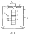
- the switch handle 5 can be at either end of the handle slot 7. If the switch 3 is a certain type of circuit breaker, the switch handle 5 can also be at an intermediate position indicating that the circuit breaker is tripped.
- a legend 109 is provided on the bottom of the carriage 25 adjacent the slot 35.
- This legend includes, as shown in Figure 6, scribe lines with the wording OFF, TRIP, and ON.
- the actuator 57 is positioned by using a screwdriver inserted in a slot 111 in the end of the threaded shaft 45 and rotating it until a scribe line 113 on the bottom of the actuator is aligned with the proper inscription on the carriage corresponding to the physical position of the switch handle 5.
- a window 123 in the top of the cover 123 of the motor operator unit 11 provides a visual indication of the position of the actuator 57, and therefore the position of the switch handle when the motor operator unit 11 is in the operative position.
- the position of the switch handle 5 is represented by the international symbol "/" for on and "O" for off appearing in the window 123 in alignment with a scribe line 127 on the cover.
- FIG 8 illustrates a schematic circuit diagram of the circuit 129 for energizing the motor 49 using the single power switch 71.
- This switch 71 is a double pole, double throw switch having one pole 131 connected to one side of the motor and a parallel resistor 133, and the other pole 135 connected to the other side of the motor and resistor.
- an OPEN supply lead 137 is connected to the motor 49 through an full wave rectifier bridge 139.
- the neutral lead 141 is connected through the interlock switch 83 so that the motor operator unit 11 must be in the operative position and the lockout plate 85 must not be in the lockout position so that the interlock switch 83 is closed.
- the motor 49 With power supplied to the OPEN lead 137, the motor 49 is energized to drive the actuator 57 to move the handle to the open position. As described above, the actuator overtravels to toggle the switch 71 to the position shown by the phantom line in Figure 8. As the CLOSE lead 143 is not energized at this point, the motor 49 stops. When it is desired to close the switch, power is applied to the CLOSE lead 143 to energize the motor 49 through the full wave rectifier bridge 145. Again, the single power switch 71 will be toggled to turn off the motor 49 after the switch handle 5 has been moved to the closed position and will also set-up the motor for driving the switch handle in the opposite direction when the OPEN lead is energized.
- the circuit 129 shown is for an AC motor 49. Alternatively, the motor 49 can be DC, in which case the bridges 139 and 145 are not needed and the negative terminals for both poles can be connected directly to the lockout switch 83.
Landscapes
- Breakers (AREA)
- Driving Mechanisms And Operating Circuits Of Arc-Extinguishing High-Tension Switches (AREA)
Applications Claiming Priority (2)
| Application Number | Priority Date | Filing Date | Title |
|---|---|---|---|
| US63270396A | 1996-04-15 | 1996-04-15 | |
| US632703 | 2003-08-01 |
Publications (2)
| Publication Number | Publication Date |
|---|---|
| EP0802549A2 true EP0802549A2 (de) | 1997-10-22 |
| EP0802549A3 EP0802549A3 (de) | 1998-11-25 |
Family
ID=24536582
Family Applications (1)
| Application Number | Title | Priority Date | Filing Date |
|---|---|---|---|
| EP97105637A Withdrawn EP0802549A3 (de) | 1996-04-15 | 1997-04-04 | Motor antrieb für elektrische Schalter |
Country Status (7)
| Country | Link |
|---|---|
| US (1) | US5693923A (de) |
| EP (1) | EP0802549A3 (de) |
| CN (1) | CN1168531A (de) |
| AU (1) | AU1772197A (de) |
| CA (1) | CA2202608A1 (de) |
| SG (1) | SG50818A1 (de) |
| ZA (1) | ZA973068B (de) |
Cited By (2)
| Publication number | Priority date | Publication date | Assignee | Title |
|---|---|---|---|---|
| FR2835093A1 (fr) * | 2002-01-24 | 2003-07-25 | Schneider Electric Ind Sa | Appareillage electrique de coupure muni d'une commande motorisee et procede de commande d'un tel appareil |
| CN101266899B (zh) * | 2007-03-13 | 2010-12-08 | 富士电机机器制御株式会社 | 电路断路器的远程操作装置 |
Families Citing this family (26)
| Publication number | Priority date | Publication date | Assignee | Title |
|---|---|---|---|---|
| US6072132A (en) * | 1999-09-28 | 2000-06-06 | Eaton Corporation | Apparatus for mounting a motor operator on a circuit |
| CN1232995C (zh) * | 2001-10-24 | 2005-12-21 | 李文丰 | 密闭型电气开关总成 |
| US6577214B1 (en) | 2002-05-07 | 2003-06-10 | Eaton Corporation | Adjustment screw cover for motor operators |
| US6659648B1 (en) * | 2002-06-07 | 2003-12-09 | Eaton Corporation | Bearing insert for motor operators |
| EP1484775A1 (de) * | 2003-06-05 | 2004-12-08 | Siemens Aktiengesellschaft | Koppelvorrichtung für Geräte mit drehbaren Schaltelementen |
| US20050275491A1 (en) * | 2004-06-15 | 2005-12-15 | Dipiero John C Jr | Remote control circuit breaker |
| FR2923074B1 (fr) * | 2007-10-29 | 2009-12-11 | Areva T & D Ag | Actionneur electromecanique et sectionneur haute ou moyenne tension muni d'un tel actionneur |
| US8183479B2 (en) * | 2009-05-01 | 2012-05-22 | General Electric Company | Lock mounting device |
| EP2436021B1 (de) * | 2009-05-25 | 2016-01-06 | ABB Schweiz AG | Schalteinheit für einen schutzschalter mit kipphebel |
| DE102010035571A1 (de) * | 2010-08-24 | 2012-03-01 | Siemens Aktiengesellschaft | Elektrischer Schalter |
| DE102011087585A1 (de) * | 2011-12-01 | 2013-06-06 | Siemens Aktiengesellschaft | Elektrischer Schalter |
| DE102011088745A1 (de) * | 2011-12-15 | 2013-06-20 | Siemens Aktiengesellschaft | Motorantrieb |
| CN103258669B (zh) * | 2013-04-17 | 2015-04-22 | 中国西电电气股份有限公司 | 一种断路器分闸位置闭锁装置 |
| US10242824B2 (en) * | 2013-06-17 | 2019-03-26 | Thomas & Betts International Llc | Lockout device for switchgear |
| US9959997B2 (en) | 2014-08-12 | 2018-05-01 | Ecolink Intelligent Technology, Inc. | Remote controlled switch cover |
| US9799469B2 (en) | 2014-08-12 | 2017-10-24 | Ecolink Intelligent Technology, Inc. | Remote controlled light switch cover assembly |
| DE102015201667B4 (de) * | 2015-01-30 | 2023-02-02 | Siemens Aktiengesellschaft | Fernantrieb für einen Leistungsschalter und Vorrichtung zum Antrieb eines Leistungsschalters |
| CN104867742A (zh) * | 2015-04-27 | 2015-08-26 | 苏州君丰辰电子科技有限公司 | 易于组装的配电开关 |
| DE102015215924A1 (de) * | 2015-08-20 | 2017-02-23 | Siemens Aktiengesellschaft | Vorrichtung zur Betätigung eines Schalters und Motorantrieb mit solch einer Vorrichtung |
| WO2017120010A1 (en) * | 2016-01-05 | 2017-07-13 | Ecolink Intelligent Technology, Inc. | Remote controlled switch cover |
| CN105575736B (zh) * | 2016-02-18 | 2017-11-07 | 江苏辉能电气有限公司 | 一种侧装电动操作模块 |
| JP6697946B2 (ja) * | 2016-04-28 | 2020-05-27 | 河村電器産業株式会社 | 電源自動切替装置 |
| JP6695732B2 (ja) * | 2016-04-28 | 2020-05-20 | 河村電器産業株式会社 | 電源自動切替装置 |
| US10395865B2 (en) | 2016-12-30 | 2019-08-27 | Ecolink Intelligent Technology, Inc. | Remote-controlled switch cover assembly |
| CN114446727B (zh) * | 2021-12-20 | 2024-04-09 | 深圳供电局有限公司 | 助推式断路器 |
| EP4339987A1 (de) * | 2022-09-13 | 2024-03-20 | Stephan Breitfeld | Aufsatzvorrichtung für ortsfeste elektrische schutzschalter zur prüfung elektrischer stromkreise |
Family Cites Families (6)
| Publication number | Priority date | Publication date | Assignee | Title |
|---|---|---|---|---|
| NL300256A (de) * | 1962-11-08 | |||
| US3296565A (en) * | 1965-01-06 | 1967-01-03 | Gen Electric | Motor-driven switch operating mechanism with indicating means |
| US4132009A (en) * | 1977-05-27 | 1979-01-02 | General Electric Company | Start system for domestic appliance |
| DE2826354A1 (de) * | 1978-06-16 | 1979-12-20 | Daimler Benz Ag | Pneumatische zentralverriegelung von tueren und klappen von kraftfahrzeugen |
| DE3640997C1 (de) * | 1986-12-01 | 1987-12-10 | Bosch Gmbh Robert | Elektromagnetisches Relais |
| DE4137779C2 (de) * | 1991-11-16 | 2001-10-04 | Moeller Gmbh | Motorantrieb für Schaltgeräte, wie Leistungsschalter oder Schutzschalter, mit Kipphebelbetätigung |
-
1997
- 1997-01-02 US US08/778,130 patent/US5693923A/en not_active Expired - Lifetime
- 1997-04-03 AU AU17721/97A patent/AU1772197A/en not_active Abandoned
- 1997-04-04 EP EP97105637A patent/EP0802549A3/de not_active Withdrawn
- 1997-04-10 ZA ZA9703068A patent/ZA973068B/xx unknown
- 1997-04-14 CA CA002202608A patent/CA2202608A1/en not_active Abandoned
- 1997-04-14 CN CN97110526A patent/CN1168531A/zh active Pending
- 1997-04-15 SG SG1997001215A patent/SG50818A1/en unknown
Cited By (4)
| Publication number | Priority date | Publication date | Assignee | Title |
|---|---|---|---|---|
| FR2835093A1 (fr) * | 2002-01-24 | 2003-07-25 | Schneider Electric Ind Sa | Appareillage electrique de coupure muni d'une commande motorisee et procede de commande d'un tel appareil |
| EP1331658A1 (de) * | 2002-01-24 | 2003-07-30 | Schneider Electric Industries SAS | Elektrischer Schaltvorrichtung mit Motorbetätigung und sein Steuerungsverfahren |
| US6621389B2 (en) | 2002-01-24 | 2003-09-16 | Schneider Electric Industries Sas | Electrical switchgear unit equipped with a motorized control and process for operating such a switchgear unit |
| CN101266899B (zh) * | 2007-03-13 | 2010-12-08 | 富士电机机器制御株式会社 | 电路断路器的远程操作装置 |
Also Published As
| Publication number | Publication date |
|---|---|
| EP0802549A3 (de) | 1998-11-25 |
| SG50818A1 (en) | 1998-07-20 |
| CN1168531A (zh) | 1997-12-24 |
| AU1772197A (en) | 1997-10-23 |
| ZA973068B (en) | 1997-11-05 |
| US5693923A (en) | 1997-12-02 |
| CA2202608A1 (en) | 1997-10-15 |
Similar Documents
| Publication | Publication Date | Title |
|---|---|---|
| US5693923A (en) | Motor operator for electrical switches | |
| US5008499A (en) | Bi-stable interlock arrangement for molded case circuit breakers | |
| US4924041A (en) | Universal circuit breaker interlock arrangement | |
| EP0450699B1 (de) | Abschliessvorrichtung mittels Vorhängeschloss von Handbedienteilen elektromechanischer Einrichtungen | |
| US4626638A (en) | Operating system for remote electrical equipment | |
| US5323131A (en) | Molded case circuit breaker motor operator | |
| US4754367A (en) | Electric switchboard cell having a positioning drive for a movably arranged switchgear and locking device for switchboard cell door | |
| US7238903B2 (en) | Electrical switching apparatus operating mechanism with operating member therefor, and enclosure assembly employing the same | |
| KR0137881B1 (ko) | 카드키를 이용한 시건장치 | |
| US20040212197A1 (en) | Overhead door locking apparatus and method of operation | |
| US6423913B1 (en) | Locking device for handle operating mechanisms | |
| EP0250223A2 (de) | Schalter mit elektrischen Abschaltmitteln | |
| US4020432A (en) | Motorized shunt trip switch operator | |
| CN212113552U (zh) | 一种三工位真空断路器 | |
| US5945648A (en) | Push-button interlock mechanism for an industrial-rated circuit breaker | |
| US3028459A (en) | Switch and enclosure therefor | |
| CN214313094U (zh) | 断路器的电动操作装置 | |
| CN214956692U (zh) | 断路器的电动操作装置 | |
| CN109524254B (zh) | 一种开关装置 | |
| CN111725022A (zh) | 一种三工位真空断路器 | |
| JP4018005B2 (ja) | 回路遮断器の外部操作ハンドル装置 | |
| CN119724997A (zh) | 一种模式转换装置及自动转换开关、用电设备 | |
| JPH11120887A (ja) | 開閉装置盤の扉インターロック装置 | |
| CN114551180A (zh) | 断路器的电动操作装置 | |
| CN215266117U (zh) | 断路器的安装结构 |
Legal Events
| Date | Code | Title | Description |
|---|---|---|---|
| PUAI | Public reference made under article 153(3) epc to a published international application that has entered the european phase |
Free format text: ORIGINAL CODE: 0009012 |
|
| AK | Designated contracting states |
Kind code of ref document: A2 Designated state(s): DE FR GB IT |
|
| PUAL | Search report despatched |
Free format text: ORIGINAL CODE: 0009013 |
|
| AK | Designated contracting states |
Kind code of ref document: A3 Designated state(s): DE FR GB IT |
|
| 17P | Request for examination filed |
Effective date: 19990518 |
|
| 17Q | First examination report despatched |
Effective date: 20010629 |
|
| STAA | Information on the status of an ep patent application or granted ep patent |
Free format text: STATUS: THE APPLICATION IS DEEMED TO BE WITHDRAWN |
|
| 18D | Application deemed to be withdrawn |
Effective date: 20020110 |