EP0802547A2 - Security device for a mobile electric element and barbecue with such device - Google Patents
Security device for a mobile electric element and barbecue with such device Download PDFInfo
- Publication number
- EP0802547A2 EP0802547A2 EP97110618A EP97110618A EP0802547A2 EP 0802547 A2 EP0802547 A2 EP 0802547A2 EP 97110618 A EP97110618 A EP 97110618A EP 97110618 A EP97110618 A EP 97110618A EP 0802547 A2 EP0802547 A2 EP 0802547A2
- Authority
- EP
- European Patent Office
- Prior art keywords
- cam
- electrical
- electrical element
- complementary
- switch
- Prior art date
- Legal status (The legal status is an assumption and is not a legal conclusion. Google has not performed a legal analysis and makes no representation as to the accuracy of the status listed.)
- Granted
Links
- 235000021168 barbecue Nutrition 0.000 title claims description 10
- 230000000295 complement effect Effects 0.000 claims description 17
- 238000001514 detection method Methods 0.000 claims description 14
- XAGFODPZIPBFFR-UHFFFAOYSA-N aluminium Chemical compound [Al] XAGFODPZIPBFFR-UHFFFAOYSA-N 0.000 abstract description 2
- 229910052782 aluminium Inorganic materials 0.000 abstract description 2
- 239000004411 aluminium Substances 0.000 abstract 1
- 238000004140 cleaning Methods 0.000 description 3
- 230000015556 catabolic process Effects 0.000 description 1
- 239000004020 conductor Substances 0.000 description 1
- 238000006073 displacement reaction Methods 0.000 description 1
- 230000005611 electricity Effects 0.000 description 1
- 238000009434 installation Methods 0.000 description 1
- 238000012986 modification Methods 0.000 description 1
- 230000004048 modification Effects 0.000 description 1
Images

Classifications
-
- A—HUMAN NECESSITIES
- A47—FURNITURE; DOMESTIC ARTICLES OR APPLIANCES; COFFEE MILLS; SPICE MILLS; SUCTION CLEANERS IN GENERAL
- A47J—KITCHEN EQUIPMENT; COFFEE MILLS; SPICE MILLS; APPARATUS FOR MAKING BEVERAGES
- A47J37/00—Baking; Roasting; Grilling; Frying
- A47J37/06—Roasters; Grills; Sandwich grills
- A47J37/07—Roasting devices for outdoor use; Barbecues
- A47J37/0704—Roasting devices for outdoor use; Barbecues with horizontal fire box
- A47J37/0709—Roasting devices for outdoor use; Barbecues with horizontal fire box with electric heating elements
-
- H—ELECTRICITY
- H01—ELECTRIC ELEMENTS
- H01H—ELECTRIC SWITCHES; RELAYS; SELECTORS; EMERGENCY PROTECTIVE DEVICES
- H01H3/00—Mechanisms for operating contacts
- H01H3/02—Operating parts, i.e. for operating driving mechanism by a mechanical force external to the switch
-
- H—ELECTRICITY
- H01—ELECTRIC ELEMENTS
- H01H—ELECTRIC SWITCHES; RELAYS; SELECTORS; EMERGENCY PROTECTIVE DEVICES
- H01H3/00—Mechanisms for operating contacts
- H01H3/02—Operating parts, i.e. for operating driving mechanism by a mechanical force external to the switch
- H01H3/16—Operating parts, i.e. for operating driving mechanism by a mechanical force external to the switch adapted for actuation at a limit or other predetermined position in the path of a body, the relative movement of switch and body being primarily for a purpose other than the actuation of the switch, e.g. for a door switch, a limit switch, a floor-levelling switch of a lift
-
- H—ELECTRICITY
- H01—ELECTRIC ELEMENTS
- H01H—ELECTRIC SWITCHES; RELAYS; SELECTORS; EMERGENCY PROTECTIVE DEVICES
- H01H9/00—Details of switching devices, not covered by groups H01H1/00 - H01H7/00
- H01H9/20—Interlocking, locking, or latching mechanisms
- H01H9/22—Interlocking, locking, or latching mechanisms for interlocking between casing, cover, or protective shutter and mechanism for operating contacts
Definitions
- the present invention relates to a safety device for a mobile electrical element.
- a safety device for an electrical appliance comprises means control and means for detecting the position of the electrical element adapted to control the operation of a single switch.
- the detection means comprise a member movable in translation against an elastic restoring force holding the movable member projecting from the electrical appliance.
- Such a movable element can easily be moved, inadvertently or intentionally, by any object bearing on the projecting part of the movable element, thus authorizing the operation of the electrical element outside of its normal operating position.
- the object of the present invention is to solve the aforementioned drawbacks and to propose an inexpensive security device while ensuring very good protection for the user.
- the safety device targeted by the invention is provided for an electric element movable with respect to complementary means cooperating in operation with the electric element in a close position, and comprises means for controlling the operation of the electric element between a on position and a stop position, means for detecting the close or distant position of the electrical element with respect to the complementary means, and a single switch adapted to be actuated between a connection position, in which the element electric is connected to means for supplying electric current, and a disconnection position, in which the electric element is disconnected from the means for supplying electricity, the switch being actuated in the disconnection position if said control means are in stop position or if the detection means detect the position far from the electrical element with respect to the complementary means.
- the detection means comprise a cam pivoted by said complementary means when the electrical element is in said close position relative to the complementary means.
- the device according to the invention is therefore very safe for the user insofar as it is necessary to exert a double action on the switch to establish the connection of the electrical element with the supply means. in electric current.
- control means comprise a second cam, the first cam of the detection means and the second cam of the control means being concentric and integral in rotation about an axis.
- the switch comprises a protruding contactor in the disconnection position and in the retracted position in the connection position.
- the second cam comes to bear on the contactor in order to move the contactor in the retracted position, when the control means are in the on position and when the detection means detect the close position of the electrical element relative to the complementary means.
- control means and the detection means therefore actuate the same contactor.
- an electric barbecue comprises a base and an electrical resistance removably mounted on this base.
- a safety device equips the electrical resistance, the additional means being constituted by the base.
- the safety device prevents the electrical resistance from starting up and thus perfectly protects the user.
- an electric barbecue 10 comprises a base 11 and an electric resistance 23 removably mounted on this base 11.
- a safety device equips the electrical resistance 23.
- the entire safety device 20 is housed in a housing 21. This can be made of plastic or aluminum.
- the electrical resistance 23 and the safety device 20 are removable with respect to the rest of the device and in particular of the base 11.
- This safety device comprises means 33 for controlling the operation of the electrical element 23 between an on position and a stop position. It also includes detection means 31 adapted to detect the close or distant position of the electrical element 23 relative to the complementary means 11.
- this safety device comprises a single switch 34 adapted to be actuated between a connection position and a disconnection position.
- electrical conductors 37, 38 enable the electrical element to be supplied with current from a current source which is not shown.
- the switch 34 comprises a contactor 35 projecting in the disconnection position and in the retracted position in the connection position.
- the contactor 35 is kept projecting by means of an elastic return means.
- the complementary means can be constituted by the base 11 of the barbecue as illustrated in FIG. 1.
- the switch 34 is adapted to connect an electrical resistor 23 to electrical supply means if and only if this resistor is in the operating position in the device and the control means 33 are in the market.
- the detection means 31 consist of a first cam 31 and the control means 33 consist of a second cam 33.
- cams 31 and 33 are concentric and are integral in rotation about an axis 33a.
- An action in rotation on the cam 31 can be achieved by means of a ramp secured to the base 11 of the barbecue.
- the cam 33 is conventionally secured to a manual control button 22 projecting from the housing 21 in which the entire safety device 20 is housed.
- complementary means such as a ramp have an action on the cam 31 and move the two cams 31 and 33 at an angle predetermined, of the order of about 15 ° in the direction of arrow F, against the return force of a spring.
- the latter is predetermined so as to stop the movement of the cam 33 before the latter is in contact with the contactor 35 of the switch 34.
- the switching on of the switch 34 can thus only be obtained when there is a combined rotation of the cams 31 and 33 by means of the ramp secured to the base 11 and the control button.
- no element projects from the housing 21 housing the entire device 20, thereby preventing the user from inadvertently moving the cam 31, thereby risking placing the switch in the connection position.
- the safety device could be mounted on a part comprising an electric motor for example, adapted to drive in movement elements such as chopper blades, whips of a mixer, allowing the engine to start only if the elements mentioned above are in place.
- the electrical element can also be only movable between an operating position and a non-operating position, without however being removable.
Landscapes
- Engineering & Computer Science (AREA)
- Food Science & Technology (AREA)
- Baking, Grill, Roasting (AREA)
- Mechanical Control Devices (AREA)
- Mechanisms For Operating Contacts (AREA)
- Rotary Switch, Piano Key Switch, And Lever Switch (AREA)
Abstract
Description
La présente invention concerne un dispositif de sécurité pour un élément électrique mobile.The present invention relates to a safety device for a mobile electrical element.
Elle concerne également un barbecue électrique comprenant une résistance électrique équipé d'un tel dispositif.It also relates to an electric barbecue comprising an electric resistance equipped with such a device.
De nombreux appareils possèdent des parties électriques qui sont amovibles afin de faciliter le nettoyage du corps de l'appareil. Il est important, pour assurer la sécurité de l'utilisateur, d'imposer la coupure de l'alimentation électrique de ces parties amovibles lorsqu'elles ne sont pas situées dans leur position normale d'utilisation. Cette exigence implique la mise en place d'un dispositif de sécurité qui empêche l'utilisateur de mettre en marche l'appareil lorsque les éléments électriques ne sont pas situés sur le corps de l'appareil.Many devices have electrical parts that are removable to facilitate cleaning of the device body. It is important, to ensure the safety of the user, to impose the cut of the electrical supply of these removable parts when they are not located in their normal position of use. This requirement involves the installation of a safety device which prevents the user from switching on the device when the electrical elements are not located on the body of the device.
On connaît dans la technique antérieure des dispositifs de sécurité montés entre les moyens d'alimentation en courant électrique et l'interrupteur de commande marche/arrêt des éléments électriques. De tels dispositifs imposent l'utilisation de deux interrupteurs montés en série, chacun de ces interrupteurs étant commandé indépendamment, soit par l'utilisateur, soit par des moyens de détection de la position de l'élément électrique par rapport au corps de l'appareil.There are known in the prior art safety devices mounted between the electrical current supply means and the on / off control switch for the electrical elements. Such devices require the use of two switches mounted in series, each of these switches being controlled independently, either by the user or by means of detecting the position of the electrical element relative to the body of the device. .
Les dispositifs de sécurité actuels présentent donc l'inconvénient d'être coûteux à réaliser et d'augmenter les risques de panne de l'appareil électrique.Current security devices therefore have the disadvantage of being costly to produce and of increasing the risk of breakdown of the electrical appliance.
Dans le document FR 2 069 677, un dispositif de sécurité pour un appareil électrique comprend des moyens de commande et des moyens de détection de la position de l'élément électrique adaptés à commander le fonctionnement d'un interrupteur unique. Les moyens de détection comprennent un élément mobile en translation contre une force de rappel élastique maintenant l'élément mobile en saillie de l'appareil électrique.In document FR 2 069 677, a safety device for an electrical appliance comprises means control and means for detecting the position of the electrical element adapted to control the operation of a single switch. The detection means comprise a member movable in translation against an elastic restoring force holding the movable member projecting from the electrical appliance.
Un tel élément mobile peut facilement être déplacé, par inadvertance ou intentionnellement, par n'importe quel objet venant en appui sur la partie en saillie de l'élément mobile, autorisant ainsi le fonctionnement de l'élément électrique hors de sa position normale de fonctionnement.Such a movable element can easily be moved, inadvertently or intentionally, by any object bearing on the projecting part of the movable element, thus authorizing the operation of the electrical element outside of its normal operating position. .
La présente invention a pour objet de résoudre les inconvénients précités et de proposer un dispositif de sécurité peu coûteux tout en assurant une très bonne protection de l'utilisateur.The object of the present invention is to solve the aforementioned drawbacks and to propose an inexpensive security device while ensuring very good protection for the user.
Le dispositif de sécurité visé par l'invention est prévu pour un élément électrique mobile par rapport à des moyens complémentaires coopérant en fonctionnement avec l'élément électrique dans une position rapprochée, et comprend des moyens de commande du fonctionnement de l'élément électrique entre une position de marche et une position d'arrêt, des moyens de détection de la position rapprochée ou éloignée de l'élément électrique par rapport aux moyens complémentaires, et un interrupteur unique adapté à être actionné entre une position de connexion, dans laquelle l'élément électrique est connecté à des moyens d'alimentation en courant électrique, et une position de déconnexion, dans laquelle l'élément électrique est déconnecté des moyens d'alimentation électrique, l'interrupteur étant actionné en position de déconnexion si lesdits moyens de commande sont en position d'arrêt ou si les moyens de détection détectent la position éloignée de l'élément électrique par rapport aux moyens complémentaires.The safety device targeted by the invention is provided for an electric element movable with respect to complementary means cooperating in operation with the electric element in a close position, and comprises means for controlling the operation of the electric element between a on position and a stop position, means for detecting the close or distant position of the electrical element with respect to the complementary means, and a single switch adapted to be actuated between a connection position, in which the element electric is connected to means for supplying electric current, and a disconnection position, in which the electric element is disconnected from the means for supplying electricity, the switch being actuated in the disconnection position if said control means are in stop position or if the detection means detect the position far from the electrical element with respect to the complementary means.
Selon l'invention les moyens de détection comprennent une came pivotée par lesdits moyens complémentaires lorsque l'élément électrique est dans ladite position rapprochée par rapport aux moyens complémentaires.According to the invention, the detection means comprise a cam pivoted by said complementary means when the electrical element is in said close position relative to the complementary means.
Ainsi, grâce à l'invention un seul interrupteur est commandé à la fois par des moyens de détection de la position de l'élément électrique par rapport à cet appareil. La mise en route des moyens électriques ne peut être réalisée que si les moyens de commande sont en position de marche et si l'élément électrique est en position normale d'utilisation.Thus, thanks to the invention only one switch is controlled at a time by means of detecting the position of the electrical element relative to this device. The electrical means can only be started up if the control means are in the on position and if the electrical element is in the normal position of use.
Le dispositif conforme à l'invention est donc d'une grande sécurité pour l'utilisateur dans la mesure où il est nécessaire d'exercer une double action sur l'interrupteur pour établir la connexion de l'élément électrique avec les moyens d'alimentation en courant électrique.The device according to the invention is therefore very safe for the user insofar as it is necessary to exert a double action on the switch to establish the connection of the electrical element with the supply means. in electric current.
En outre, l'utilisation d'une came rotative comme moyen de détection rend plus mal aisée toute manipulation accidentelle de ces moyens de détection.In addition, the use of a rotary cam as a detection means makes any accidental manipulation of these detection means more difficult.
Selon une version avantageuse de l'invention, les moyens de commande comprennent une seconde came, la première came des moyens de détection et la seconde came des moyens de commande étant concentriques et solidaires en rotation autour d'un axe.According to an advantageous version of the invention, the control means comprise a second cam, the first cam of the detection means and the second cam of the control means being concentric and integral in rotation about an axis.
Selon une autre version avantageuse de l'invention, l'interrupteur comprend un contacteur en saillie dans la position de déconnexion et en position escamotée dans la position de connexion. La seconde came vient en appui sur le contacteur afin de déplacer le contacteur en position escamotée, lorsque les moyens de commande sont en position de marche et lorsque les moyens de détection détectent la position rapprochée de l'élément électrique par rapport aux moyens complémentaires.According to another advantageous version of the invention, the switch comprises a protruding contactor in the disconnection position and in the retracted position in the connection position. The second cam comes to bear on the contactor in order to move the contactor in the retracted position, when the control means are in the on position and when the detection means detect the close position of the electrical element relative to the complementary means.
Les moyens de commande et les moyens de détection actionnent donc un même contacteur.The control means and the detection means therefore actuate the same contactor.
Selon un autre aspect de l'invention, un barbecue électrique comprend une embase et une résistance électrique montée de manière amovible sur cette embase.According to another aspect of the invention, an electric barbecue comprises a base and an electrical resistance removably mounted on this base.
Conformément à l'invention, un dispositif de sécurité tel que décrit ci-dessus équipe la résistance électrique, les moyens complémentaires étant constitués par l'embase.According to the invention, a safety device as described above equips the electrical resistance, the additional means being constituted by the base.
Par conséquent, dès que la résistance électrique est retirée de l'embase, pour faciliter le nettoyage de celle-ci par exemple, le dispositif de sécurité conforme à l'invention empêche la mise en route de la résistance électrique et protège ainsi parfaitement l'utilisateur.Consequently, as soon as the electrical resistance is removed from the base, to facilitate cleaning thereof, for example, the safety device according to the invention prevents the electrical resistance from starting up and thus perfectly protects the user.
D'autres avantages et particularités de l'invention apparaîtront encore dans la description ci-après.Other advantages and features of the invention will become apparent in the description below.
Aux dessins annexés donnés à titre d'exemples non limitatifs:
- la figure 1 est une vue en perspective d'un barbecue électrique conforme à l'invention;
- la figure 2 est une vue en perspective d'une résistance électrique équipée d'un dispositif de sécurité conforme à l'invention; et
- la figure 3 est une vue schématique d'un dispositif de sécurité selon un mode de réalisation de l'invention.
- Figure 1 is a perspective view of an electric barbecue according to the invention;
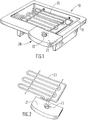
- Figure 2 is a perspective view of an electrical resistance equipped with a safety device according to the invention; and
- Figure 3 is a schematic view of a security device according to an embodiment of the invention.
Afin de mieux comprendre l'invention, on va décrire l'application du dispositif de sécurité à un barbecue électrique, cet exemple n'étant donné qu'à titre d'illustration.In order to better understand the invention, the application of the safety device to an electric barbecue will be described, this example being given only by way of illustration.
En référence tout d'abord à la figure 1, un barbecue électrique 10 comprend une embase 11 et une résistance électrique 23 montée de manière amovible sur cette embase 11.Referring firstly to FIG. 1, an
Dans un tel appareil, il est avantageux de pouvoir retirer la résistance électrique pour faciliter le nettoyage de l'embase 11.In such an apparatus, it is advantageous to be able to remove the electrical resistance to facilitate cleaning of the base 11.
Un dispositif de sécurité, tel qu'il sera décrit ci-après en détail, équipe la résistance électrique 23. L'ensemble du dispositif de sécurité 20 est logé dans un boîtier 21. Celui-ci peut être en plastique ou en aluminium.A safety device, as will be described below in detail, equips the
Comme mieux représenté à la figure 2, la résistance électrique 23 et le dispositif de sécurité 20 sont amovibles par rapport au reste de l'appareil et notamment de l'embase 11.As best shown in FIG. 2, the
En référence à la figure 3, on va décrire la structure du dispositif de sécurité conforme à l'invention.Referring to Figure 3, we will describe the structure of the safety device according to the invention.
Ce dispositif de sécurité comprend des moyens de commande 33 du fonctionnement de l'élément électrique 23 entre une position de marche et une position d'arrêt. Il comprend également des moyens de détection 31 adaptés à détecter la position rapprochée ou éloignée de l'élément électrique 23 par rapport aux moyens complémentaires 11.This safety device comprises means 33 for controlling the operation of the
Conformément à l'invention, ce dispositif de sécurité comprend un interrupteur unique 34 adapté à être actionné entre une position de connexion et une position de déconnexion.According to the invention, this safety device comprises a single switch 34 adapted to be actuated between a connection position and a disconnection position.
De manière connue, des conducteurs électriques 37, 38 permettent d'alimenter en courant l'élément électrique à partir d'une source de courant non représentée.In known manner,
L'interrupteur 34 comprend un contacteur 35 en saillie dans la position de déconnexion et en position escamotée dans la position de connexion.The switch 34 comprises a
Le contacteur 35 est maintenu en saillie grâce à un moyen de rappel élastique.The
Les moyens complémentaires peuvent être constitués par l'embase 11 du barbecue tel qu'illustré à la figure 1.The complementary means can be constituted by the base 11 of the barbecue as illustrated in FIG. 1.
Conformément à l'invention, l'interrupteur 34 est adapté à connecter une résistance électrique 23 à des moyens d'alimentation électrique si et seulement si cette résistance est en position de fonctionnement dans l'appareil et les moyens de commande 33 sont en position de marche.According to the invention, the switch 34 is adapted to connect an
Les moyens de détection 31 sont constitués d'une première came 31 et les moyens de commande 33 sont constitués d'une seconde came 33.The detection means 31 consist of a
Ces deux cames 31 et 33 sont concentriques et sont solidaires en rotation autour d'un axe 33a.These two
Une action en rotation sur la came 31 peut être réalisée au moyen d'une rampe solidaire de l'embase 11 du barbecue.An action in rotation on the
La came 33 est de manière classique solidaire d'un bouton de commande manuelle 22 faisant saillie sur le boîtier 21 dans lequel est logé l'ensemble du dispositif de sécurité 20.The
En fonctionnement, lorsque l'utilisateur place l'élément électrique équipé du dispositif de sécurité sur l'embase 11, des moyens complémentaires tels qu'une rampe ont une action sur la came 31 et déplacent les deux cames 31 et 33 d'un angle prédéterminé, de l'ordre de 15° environ dans le sens de la flèche F, à l'encontre de la force de rappel d'un ressort.In operation, when the user places the electrical element equipped with the safety device on the base 11, complementary means such as a ramp have an action on the
Ensuite, lorsque l'utilisateur tourne le bouton de commande 22, également suivant la flèche F, les cames 31 et 33 sont pivotées d'un angle supplémentaire, de sorte que la came 33 vienne en appui sur le contacteur 35 de l'interrupteur 34 et permette ainsi la mise en marche de l'élément électrique.Then, when the user turns the
Lorsque l'élément électrique n'est pas en place sur l'embase 11, la force de rappel du ressort précité entraîne en rotation, dans le sens opposé à la flèche F, les deux cames 31 et 33.When the electrical element is not in place on the base 11, the return force of the aforementioned spring rotates, in the opposite direction to arrow F, the two
Lorsque l'utilisateur agit sur le bouton de commande solidaire de la came 33, il entraîne en rotation les cames 31 et 33 dans le sens de la flèche F selon un déplacement angulaire maximum.When the user acts on the control button integral with the
Ce dernier est prédéterminé de manière à arrêter le déplacement de la came 33 avant que cette dernière ne soit en contact avec le contacteur 35 de l'interrupteur 34.The latter is predetermined so as to stop the movement of the
La mise en marche de l'interrupteur 34 ne peut ainsi être obtenue que lorsqu'il y a une rotation combinée des cames 31 et 33 par l'intermédiaire de la rampe solidaire de l'embase 11 et du bouton de commande.The switching on of the switch 34 can thus only be obtained when there is a combined rotation of the
Dans cette réalisation, aucun élément ne fait saillie du boîtier 21 logeant l'ensemble du dispositif 20, évitant ainsi que l'utilisateur puisse, par mégarde, déplacer la came 31, risquant ainsi de placer l'interrupteur en position de connexion.In this embodiment, no element projects from the
Bien entendu, de nombreuses modifications peuvent être apportées à l'exemple de réalisation décrit ci-dessus sans sortir du cadre de l'invention.Of course, numerous modifications can be made to the embodiment described above without departing from the scope of the invention.
Ainsi, le dispositif de sécurité pourrait être monté sur une partie comprenant un moteur électrique par exemple, adapté à entraîner en mouvement des éléments tels que des lames de hachoir, des fouets d'un batteur, ne permettant la mise en route du moteur que si les éléments cités ci-dessus sont en place.Thus, the safety device could be mounted on a part comprising an electric motor for example, adapted to drive in movement elements such as chopper blades, whips of a mixer, allowing the engine to start only if the elements mentioned above are in place.
L'élément électrique peut également n'être que mobile entre une position de fonctionnement et une position de non fonctionnement, sans être pour autant amovible.The electrical element can also be only movable between an operating position and a non-operating position, without however being removable.
Claims (8)
Applications Claiming Priority (3)
| Application Number | Priority Date | Filing Date | Title |
|---|---|---|---|
| FR9405618A FR2719720B1 (en) | 1994-05-06 | 1994-05-06 | Safety device for a mobile electric element and electric barbecue equipped with such a device. |
| FR9405618 | 1994-05-06 | ||
| EP95401002A EP0681307B1 (en) | 1994-05-06 | 1995-05-02 | Security device for a mobile electric element and barbecue with such device |
Related Parent Applications (2)
| Application Number | Title | Priority Date | Filing Date |
|---|---|---|---|
| EP95401002.1 Division | 1995-05-02 | ||
| EP95401002A Division EP0681307B1 (en) | 1994-05-06 | 1995-05-02 | Security device for a mobile electric element and barbecue with such device |
Publications (3)
| Publication Number | Publication Date |
|---|---|
| EP0802547A2 true EP0802547A2 (en) | 1997-10-22 |
| EP0802547A3 EP0802547A3 (en) | 1997-11-12 |
| EP0802547B1 EP0802547B1 (en) | 2000-11-22 |
Family
ID=9462981
Family Applications (2)
| Application Number | Title | Priority Date | Filing Date |
|---|---|---|---|
| EP97110618A Expired - Lifetime EP0802547B1 (en) | 1994-05-06 | 1995-05-02 | Security device for a mobile electric element and barbecue with such device |
| EP95401002A Expired - Lifetime EP0681307B1 (en) | 1994-05-06 | 1995-05-02 | Security device for a mobile electric element and barbecue with such device |
Family Applications After (1)
| Application Number | Title | Priority Date | Filing Date |
|---|---|---|---|
| EP95401002A Expired - Lifetime EP0681307B1 (en) | 1994-05-06 | 1995-05-02 | Security device for a mobile electric element and barbecue with such device |
Country Status (5)
| Country | Link |
|---|---|
| US (2) | US5621198A (en) |
| EP (2) | EP0802547B1 (en) |
| CA (1) | CA2148659C (en) |
| DE (4) | DE69519479T2 (en) |
| FR (1) | FR2719720B1 (en) |
Cited By (1)
| Publication number | Priority date | Publication date | Assignee | Title |
|---|---|---|---|---|
| EP1571518A1 (en) * | 2004-03-03 | 2005-09-07 | Seb S.A. | Detachable heating subassembly adapted to be placed on the main body of a cooking device |
Families Citing this family (9)
| Publication number | Priority date | Publication date | Assignee | Title |
|---|---|---|---|---|
| FR2719720B1 (en) * | 1994-05-06 | 1996-07-12 | Seb Sa | Safety device for a mobile electric element and electric barbecue equipped with such a device. |
| FR2771615B1 (en) * | 1997-11-28 | 2000-07-28 | Moulinex Sa | ELECTRIC COOKING APPLIANCE, PARTICULARLY GRILL |
| TW502864U (en) * | 2001-09-07 | 2002-09-11 | High Tech Comp Corp | Power switch device which is easy to turn on and difficult to turn off |
| FR2848799B1 (en) * | 2002-12-23 | 2005-05-27 | Seb Sa | SECURITY DEVICE FOR A REMOVABLE HEATING SUBASSEMBLY ADAPTED TO BE POSITIONED ON A MAIN BODY OF A COOKING APPARATUS |
| US7134475B2 (en) * | 2004-10-29 | 2006-11-14 | United Technologies Corporation | Investment casting cores and methods |
| FR2881267A1 (en) * | 2005-01-21 | 2006-07-28 | Seb Sa | HOUSEHOLD APPLIANCE COMPRISING A TRIPLE ACTION SECURITY DEVICE |
| SE530256C2 (en) | 2005-12-16 | 2008-04-15 | Moelnlycke Health Care Ab | Method for making holes in heat-meltable materials |
| US7974526B2 (en) * | 2008-02-21 | 2011-07-05 | Honor Tone, Ltd. | Outdoor heater |
| CN113745016B (en) * | 2020-05-27 | 2024-01-16 | 浙江天喜厨电股份有限公司 | Micro-gap switch and have this micro-gap switch's air fryer |
Family Cites Families (13)
| Publication number | Priority date | Publication date | Assignee | Title |
|---|---|---|---|---|
| FR891212A (en) * | 1942-10-19 | 1944-03-01 | Soudure Electr | Adjustable cam device |
| GB1019921A (en) * | 1963-02-27 | 1966-02-09 | Cecil Bertram Annable | Improvements in electric liquid-heating means |
| CA898311A (en) * | 1969-11-19 | 1972-04-18 | Juseret Roger | Dispositif de manoeuvre pour appareils electriques |
| US4034201A (en) * | 1975-04-28 | 1977-07-05 | Clairol Incorporated | Steam curling iron having interchangeable hair winding mandrels |
| US4214150A (en) * | 1978-05-10 | 1980-07-22 | Emerson Electric Co. | Electric heating elements |
| US4164644A (en) * | 1978-08-07 | 1979-08-14 | Courtesy Interstate Corporation | Portable electrical heating unit with automatic cutoff |
| CA1254932A (en) * | 1984-07-04 | 1989-05-30 | Sekisuke Yamanaka | Digital switch |
| DE3430878A1 (en) * | 1984-08-22 | 1986-03-06 | Heddernheimer Metallwarenfabrik GmbH, 7750 Konstanz | Device for roasting |
| US4577181A (en) * | 1985-03-04 | 1986-03-18 | Bernard Lipscher | Alarm system for electric range |
| NZ226583A (en) * | 1987-10-16 | 1990-01-29 | Jonathon Edward Farrell | Switch mechanism: actuator disabled on removal of cover |
| DE3926098C2 (en) * | 1989-08-08 | 1995-08-10 | Brill Produktions Gmbh | Switch-on device for electrically operated devices |
| FR2685992B1 (en) * | 1992-01-08 | 1994-04-08 | Seb Sa | ELECTRIC COOKING PLATE WITH TEMPERATURE SENSOR. |
| FR2719720B1 (en) * | 1994-05-06 | 1996-07-12 | Seb Sa | Safety device for a mobile electric element and electric barbecue equipped with such a device. |
-
1994
- 1994-05-06 FR FR9405618A patent/FR2719720B1/en not_active Expired - Lifetime
-
1995
- 1995-05-01 US US08/431,850 patent/US5621198A/en not_active Expired - Fee Related
- 1995-05-02 DE DE69519479T patent/DE69519479T2/en not_active Expired - Fee Related
- 1995-05-02 DE DE69503962T patent/DE69503962T2/en not_active Expired - Fee Related
- 1995-05-02 DE DE0681307T patent/DE681307T1/en active Pending
- 1995-05-02 EP EP97110618A patent/EP0802547B1/en not_active Expired - Lifetime
- 1995-05-02 DE DE0802547T patent/DE802547T1/en active Pending
- 1995-05-02 EP EP95401002A patent/EP0681307B1/en not_active Expired - Lifetime
- 1995-05-04 CA CA002148659A patent/CA2148659C/en not_active Expired - Fee Related
-
1997
- 1997-01-03 US US08/778,630 patent/US5739493A/en not_active Expired - Fee Related
Cited By (2)
| Publication number | Priority date | Publication date | Assignee | Title |
|---|---|---|---|---|
| EP1571518A1 (en) * | 2004-03-03 | 2005-09-07 | Seb S.A. | Detachable heating subassembly adapted to be placed on the main body of a cooking device |
| FR2867345A1 (en) * | 2004-03-03 | 2005-09-09 | Seb Sa | REMOVABLE HEATER ASSEMBLY ADAPTED TO BE POSITIONED ON THE MAIN BODY OF A COOKING APPARATUS |
Also Published As
| Publication number | Publication date |
|---|---|
| US5621198A (en) | 1997-04-15 |
| DE802547T1 (en) | 1998-10-22 |
| EP0802547B1 (en) | 2000-11-22 |
| CA2148659C (en) | 2005-07-12 |
| FR2719720B1 (en) | 1996-07-12 |
| DE69519479T2 (en) | 2001-06-21 |
| EP0802547A3 (en) | 1997-11-12 |
| DE69503962D1 (en) | 1998-09-17 |
| DE681307T1 (en) | 1996-05-02 |
| DE69519479D1 (en) | 2000-12-28 |
| FR2719720A1 (en) | 1995-11-10 |
| EP0681307B1 (en) | 1998-08-12 |
| EP0681307A1 (en) | 1995-11-08 |
| US5739493A (en) | 1998-04-14 |
| DE69503962T2 (en) | 1999-03-18 |
| CA2148659A1 (en) | 1995-11-07 |
Similar Documents
| Publication | Publication Date | Title |
|---|---|---|
| EP1998656B1 (en) | Culinary preparation appliance with safety device | |
| EP0802547B1 (en) | Security device for a mobile electric element and barbecue with such device | |
| EP2291888A1 (en) | Device for secure electrical connection | |
| FR2849817A1 (en) | MIRROR FOR A VEHICLE COMPRISING A MIRROR MOUNTED SWIVELING ON TWO PERPENDICULAR AXES | |
| FR2773978A1 (en) | Hand-held domestic electric appliance with multi-position control switch, in particular domestic food mixer | |
| FR2942197A1 (en) | BRAKE HANDLE BRAKE DEVICE FOR MOTORIZED WHEELED VEHICLE | |
| WO2001019225A2 (en) | Hand held electrical mixing beater | |
| FR2484692A1 (en) | DEVICE FOR AUTOMATICALLY CUTTING THE POWER SUPPLY OF AN ENGINE AND USE THEREOF | |
| EP2337046A1 (en) | Device for controlling a switch of a household appliance | |
| EP1629167B1 (en) | Household appliance hinge with two hinged panels | |
| EP3989788B1 (en) | Motorised housing for a household appliance configured to be hand-held | |
| EP0818795B1 (en) | Switch having two movable contacts such as switch for roller shutter | |
| EP1978607A1 (en) | Electrical charger equipped with an articulated bonding pad | |
| CH656341A5 (en) | APPARATUS FOR MOWING, ESPECIALLY SHEEP. | |
| FR2670273A1 (en) | DEVICE FOR CONTROLLING A MICROWAVE OVEN. | |
| EP2975986B1 (en) | Food preparation appliance | |
| FR2900774A3 (en) | MOTOR ELEMENT FOR ELECTRIC LOCK | |
| FR2696332A1 (en) | Safe pivoting electric resistance element for cooker - has rotary connector with conducting and insulating areas in spring loaded contact, joined to supply in insulating housing | |
| WO1994013952A1 (en) | Device for mounting an electrical heating component on a thermal actuator and arrangement thereof in a housing | |
| FR2738666A1 (en) | Three-position sprung control knob switch for electrical equipment, e.g. food processor | |
| EP0609161A1 (en) | Control for combined microwave and grill oven | |
| FR2789283A3 (en) | AUTOMATIC POWER CHANGE DEVICE FOR FOOD PROCESSING APPARATUS | |
| EP1647041A2 (en) | Differential switch provided with a test circuit | |
| FR2883407A1 (en) | Electromechanical control device for e.g. mobile socket, has wheel defined as outer and inner parts of which outer part tilts inner part during rotation of outer part such that inner part supports on switches, when parts are connected | |
| FR2818526A1 (en) | Kitchen appliance design especially for mini-grinders or mincers, has security device for preventing operation of motor when casing is inclined more than 45 degrees |
Legal Events
| Date | Code | Title | Description |
|---|---|---|---|
| PUAI | Public reference made under article 153(3) epc to a published international application that has entered the european phase |
Free format text: ORIGINAL CODE: 0009012 |
|
| PUAL | Search report despatched |
Free format text: ORIGINAL CODE: 0009013 |
|
| AC | Divisional application: reference to earlier application |
Ref document number: 681307 Country of ref document: EP |
|
| AK | Designated contracting states |
Kind code of ref document: A2 Designated state(s): BE DE NL |
|
| AK | Designated contracting states |
Kind code of ref document: A3 Designated state(s): BE DE NL |
|
| 17P | Request for examination filed |
Effective date: 19980306 |
|
| TCNL | Nl: translation of patent claims filed | ||
| DET | De: translation of patent claims | ||
| 17Q | First examination report despatched |
Effective date: 19990204 |
|
| GRAG | Despatch of communication of intention to grant |
Free format text: ORIGINAL CODE: EPIDOS AGRA |
|
| GRAG | Despatch of communication of intention to grant |
Free format text: ORIGINAL CODE: EPIDOS AGRA |
|
| GRAH | Despatch of communication of intention to grant a patent |
Free format text: ORIGINAL CODE: EPIDOS IGRA |
|
| GRAH | Despatch of communication of intention to grant a patent |
Free format text: ORIGINAL CODE: EPIDOS IGRA |
|
| GRAH | Despatch of communication of intention to grant a patent |
Free format text: ORIGINAL CODE: EPIDOS IGRA |
|
| GRAA | (expected) grant |
Free format text: ORIGINAL CODE: 0009210 |
|
| AC | Divisional application: reference to earlier application |
Ref document number: 681307 Country of ref document: EP |
|
| AK | Designated contracting states |
Kind code of ref document: B1 Designated state(s): BE DE NL |
|
| PG25 | Lapsed in a contracting state [announced via postgrant information from national office to epo] |
Ref country code: NL Free format text: LAPSE BECAUSE OF FAILURE TO SUBMIT A TRANSLATION OF THE DESCRIPTION OR TO PAY THE FEE WITHIN THE PRESCRIBED TIME-LIMIT Effective date: 20001122 |
|
| REF | Corresponds to: |
Ref document number: 69519479 Country of ref document: DE Date of ref document: 20001228 |
|
| NLV1 | Nl: lapsed or annulled due to failure to fulfill the requirements of art. 29p and 29m of the patents act | ||
| PG25 | Lapsed in a contracting state [announced via postgrant information from national office to epo] |
Ref country code: BE Free format text: LAPSE BECAUSE OF NON-PAYMENT OF DUE FEES Effective date: 20010531 |
|
| PLBE | No opposition filed within time limit |
Free format text: ORIGINAL CODE: 0009261 |
|
| STAA | Information on the status of an ep patent application or granted ep patent |
Free format text: STATUS: NO OPPOSITION FILED WITHIN TIME LIMIT |
|
| 26N | No opposition filed | ||
| BERE | Be: lapsed |
Owner name: S.A. SEB Effective date: 20010531 |
|
| PGFP | Annual fee paid to national office [announced via postgrant information from national office to epo] |
Ref country code: DE Payment date: 20080508 Year of fee payment: 14 |
|
| PG25 | Lapsed in a contracting state [announced via postgrant information from national office to epo] |
Ref country code: DE Free format text: LAPSE BECAUSE OF NON-PAYMENT OF DUE FEES Effective date: 20091201 |