EP0802472B1 - Steuerung einer Klimaregelungsanlage durch ein Schliessystem - Google Patents
Steuerung einer Klimaregelungsanlage durch ein Schliessystem Download PDFInfo
- Publication number
- EP0802472B1 EP0802472B1 EP19970400875 EP97400875A EP0802472B1 EP 0802472 B1 EP0802472 B1 EP 0802472B1 EP 19970400875 EP19970400875 EP 19970400875 EP 97400875 A EP97400875 A EP 97400875A EP 0802472 B1 EP0802472 B1 EP 0802472B1
- Authority
- EP
- European Patent Office
- Prior art keywords
- lock
- control means
- energy control
- room
- mode
- Prior art date
- Legal status (The legal status is an assumption and is not a legal conclusion. Google has not performed a legal analysis and makes no representation as to the accuracy of the status listed.)
- Expired - Lifetime
Links
- 230000007613 environmental effect Effects 0.000 title description 9
- 238000001514 detection method Methods 0.000 claims description 10
- 238000000034 method Methods 0.000 claims description 5
- 238000010438 heat treatment Methods 0.000 description 8
- 238000010586 diagram Methods 0.000 description 7
- 230000015654 memory Effects 0.000 description 6
- 238000001816 cooling Methods 0.000 description 5
- 238000005265 energy consumption Methods 0.000 description 5
- 238000004378 air conditioning Methods 0.000 description 2
- 230000005540 biological transmission Effects 0.000 description 1
- 230000006870 function Effects 0.000 description 1
- 239000002184 metal Substances 0.000 description 1
- 210000003813 thumb Anatomy 0.000 description 1
Images


Classifications
-
- F—MECHANICAL ENGINEERING; LIGHTING; HEATING; WEAPONS; BLASTING
- F24—HEATING; RANGES; VENTILATING
- F24F—AIR-CONDITIONING; AIR-HUMIDIFICATION; VENTILATION; USE OF AIR CURRENTS FOR SCREENING
- F24F11/00—Control or safety arrangements
- F24F11/30—Control or safety arrangements for purposes related to the operation of the system, e.g. for safety or monitoring
- F24F11/46—Improving electric energy efficiency or saving
-
- G—PHYSICS
- G05—CONTROLLING; REGULATING
- G05D—SYSTEMS FOR CONTROLLING OR REGULATING NON-ELECTRIC VARIABLES
- G05D23/00—Control of temperature
- G05D23/19—Control of temperature characterised by the use of electric means
- G05D23/1902—Control of temperature characterised by the use of electric means characterised by the use of a variable reference value
-
- F—MECHANICAL ENGINEERING; LIGHTING; HEATING; WEAPONS; BLASTING
- F24—HEATING; RANGES; VENTILATING
- F24F—AIR-CONDITIONING; AIR-HUMIDIFICATION; VENTILATION; USE OF AIR CURRENTS FOR SCREENING
- F24F11/00—Control or safety arrangements
- F24F11/30—Control or safety arrangements for purposes related to the operation of the system, e.g. for safety or monitoring
-
- F—MECHANICAL ENGINEERING; LIGHTING; HEATING; WEAPONS; BLASTING
- F24—HEATING; RANGES; VENTILATING
- F24F—AIR-CONDITIONING; AIR-HUMIDIFICATION; VENTILATION; USE OF AIR CURRENTS FOR SCREENING
- F24F2110/00—Control inputs relating to air properties
-
- F—MECHANICAL ENGINEERING; LIGHTING; HEATING; WEAPONS; BLASTING
- F24—HEATING; RANGES; VENTILATING
- F24F—AIR-CONDITIONING; AIR-HUMIDIFICATION; VENTILATION; USE OF AIR CURRENTS FOR SCREENING
- F24F2120/00—Control inputs relating to users or occupants
-
- F—MECHANICAL ENGINEERING; LIGHTING; HEATING; WEAPONS; BLASTING
- F24—HEATING; RANGES; VENTILATING
- F24F—AIR-CONDITIONING; AIR-HUMIDIFICATION; VENTILATION; USE OF AIR CURRENTS FOR SCREENING
- F24F2120/00—Control inputs relating to users or occupants
- F24F2120/10—Occupancy
Definitions
- the present invention relates to electronic lock systems and, more specifically, to a combination of an electronic lock system and an environmental control system for controlling the heating and cooling units in a room.
- Electronic lock systems are commonly employed in hotels, motels, cruise ships and ferries where a room is rented to a guest for a short period of time and there is a need for a high level of security.
- the electronic lock system in essence, provides each new guest with a new key and rekeys the lock for each new key used in the lock.
- an electronic lock system comprises a key generating station which is located at the check-in counter or front desk of the hotel and an electronic lock which is mounted in a door of a room and provides access to the room. The lock is opened by a key having magnetic data (key code) thereon.
- the key is in the form of a card and the magnetic data is encoded onto the key by the key generating station when it is assigned to the guest at the front desk.
- the lock has a means to read the magnetic data on the key and a microcontroller to compare the key code with an access code.
- the access code is either generated by the microcontroller through an algorithm or is stored in the memory of the microcontroller. If there is a match between the access code and the key code, then the lock opens and allows access to the room.
- the key generating station is either hard wired to the electronic lock so that it can communicate the new key code to the electronic lock; or the key generating station and the microcontroller use the same algorithm to calculate the codes; or the key generating station and the microcontroller store the same codes in their memories.
- the lock system invalidates a guest key.
- the mere use of a new guest key with a new guest key code causes the previously used guest key code to be invalidated.
- the key code includes a start time and an end time or a time period, e.g. a number of hours, during which the guest key code is valid.
- the use of a time period invalidates the guest key code at the end of the time period, without the need for a new guest key to be inserted in the lock. The use of time thus allows greater control by management of the access to the room by the guests.
- Environmental control systems are used to control the energy consumption of the various electrical appliances in a room.
- hotels employ them to control the heating and cooling unit (HVAC units) of the room.
- An environmental control system conventionally comprises a motion detector mounted on a wall of the room for detecting when the guest is in the room; a door switch which detects a change in state of the door; e.g. opening and closing of the door; and an energy control unit which is connected to the various electrical appliances of the room.
- the energy control unit controls the energy consumption of the various electrical appliances in the room, especially the heating, ventilating and air conditioning (HVAC) unit.
- HVAC heating, ventilating and air conditioning
- the motion detector is activated to detect the presence of a guest in the room.
- the motion detector then sends a signal to the energy control unit to set the temperature to some acceptable level.
- the door switch changes state and the motion detector is activated and detects the absence of the guest.
- the motion detector then sends a signal to the energy control unit and the energy control unit resets the temperature to allow for a broader temperature range and thus less energy consumption. For instance, in the winter, the guest may set the room temperature at 75 °F (25 °C). However, the hotel management prefers to have the room temperature at 60 °F (15 °C) when the guest is not in the room.
- the energy control sets the heating unit to the various temperatures depending upon whether the motion detector detects the presence or absence of the guest in the room.
- the energy control unit can be connected to other electrical appliances other than the HVAC unit.
- the energy control unit can be connected to the lights, television and radio to insure that these are turned off when the guest leaves the room.
- WO 95 20782 and US 4 425 864 show such a conventional environmental control system.
- the room when a guest has checked into a hotel and has been assigned a room, the room is referred to as being in a sold state. If a room has not been assigned to a guest or if the guest has checked out, then the room is referred to as being in the unsold state.
- a room when a room is in the sold state, it can be either in an occupied state, i.e. the guest is present in the room, or in an unoccupied state, i.e. the guest is absent from the room.
- EP 0 696 769 teaches such a system having different temperature regimes.
- the hotel management sets the unsold temperature range at between 85 °F (30 °C) and 50 °F (10°C) and the sold temperature range at between 75 °F (25 °C) and 60 °F (15 °C).
- the heating/cooling units are off so long as the room temperature stays within the range.
- the hotel guest is able to further adjust the temperature range to his specific preference, for example at 70 °F (20 °C) when he occupies the room.
- the motion detector communicates with the energy control unit either by wiring of the two units together or by electromagnetic waves (radio or light). Additionally, some environmental control systems as well as some electronic locks are wired to a main terminal which is located at a main desk so that they can be controlled from the main desk.
- the present invention combines a stand-alone electronic lock system with an energy control means, and provides for the lock to instruct the energy control means when to move from the unsold to the sold state.
- the electronic lock system communicates to the energy control means when a guest has used a guest card key in the lock such that the energy control means moves from the unsold state to the sold state.
- a motion detector and a door switch is employed such that the sold state can be further divided between an occupied state and an unoccupied state. This provides for additional energy savings when the guest is not in the room.
- the present invention is directed to an electronic lock system having an electronic lock mounted in a door of a room to provide access to said room, a guest key card with a guest key code thereon for opening said lock, and an energy control means for controlling temperature in said room, the lock having a means for storing a guest access code, a means for reading said guest key code when said guest key card is inserted into said lock, a means for comparing said guest key code with said guest access code such that if said guest key code matches said guest access code said lock opens, and a means for communicating directly with said energy control means, said energy control means having a means for communicating directly with said lock, and having at least two modes of operation, a sold mode and an unsold mode, said unsold mode having a wider temperature range than said sold mode temperature range, the improvement comprising :
- the lock communicates the first time a new guest key card is used in the lock such that the energy control means moves to a sold mode and to insure that after a guest key card is used in the lock the energy control means is in the sold mode.
- a hotel staff or other card key will have to be used to move the energy control means from the sold to the unsold state.
- Either the lock or the energy control means has a clock which keeps track of the amount of time that has gone by since the guest key card was last used in the lock, and automatically after a set period of time, say 24 hours, instructs the energy control means to move from a sold to an unsold mode.
- the guest key card has a start time thereon, such that when it is inserted into the lock, the start time dictates when to move the room from the unsold to the sold state and either the end time or the time period during which the key is valid, such that at the end time or the end of the time period during which the key is valid, the lock instructs the energy control means to move from the sold to the unsold mode.
- the start time and end time/time period can be sent to the energy control means each time the guest key card is used in the lock; or the first time the guest key card is used in the lock.
- the energy control means must have a clock so that the energy control means knows when the end time has arrived.
- the lock has a clock and sends a signal to the energy control means when to start the sold mode and when to end the sold mode and move to the unsold mode.
- the electronic lock system further comprises a means for detecting when a person is in said room.
- a means for detection comprises a detector mounted on the wall or contained in the lock, and a door switch mounted to the door frame or included in the lock.
- the detector is preferably a motion detector such as a passive infrared detector (PIR), or an ultrasonic detector.
- PIR passive infrared detector
- ultrasonic detector Such means are conventional.
- the temperature is set to that which was chosen by the guest, while during the unoccupied mode the energy control means returns the temperature to the sold mode as set by the hotel management.
- the hotel management may set the sold temperature range at 60°F (15°C) to 75°F (25°C) while the guest sets the temperature at 70°F (20°C).
- the energy control means maintains the temperature at about 70°F (20°C).
- the electronic lock system detects that the guest has left, and the energy control means moves to the unoccupied mode allowing the room temperature to drift within the range of 60°F (15°C) and 75°F (25°C).
- the electronic lock system Upon detecting the return of the guest, the electronic lock system has the energy control means return the room temperature to about 70°F (20°C) as set by the guest.
- the electronic lock system has:
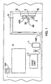
- FIG. 1 shows schematically a vertical elevation of interior wall A of a room having door B therein. Against wall A is mounted HVAC unit C for the,room and near HVAC unit C is mounted energy control means 1.
- Door B has lock 2 mounted therein. The door B is provided with lock 2 according to the present invention.
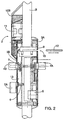
- FIG. 2 shows enlarged a vertical section through a part of the door B with lock 2, seen along line II-II on FIG. 1.
- Lock 2 comprises exterior escutcheon 3A and interior escutcheon 3B.
- Exterior door handle 4A is used to open door B from the outside while interior door handle 4B is used to open door B from the inside of the room.
- a conventional cylinder lock 5 is set in lock 2 with deadbolt thumb turn 5A which is intended for use by the guests for additional security.
- Lock case 6 contains an electronic locking device which contains mechanical means for locking door B in the door jamb.
- Pin 7 interconnects interior door handle 4B to exterior door handle 4A. Pin 7 is locked by means of the electronic locking device contained in lock case 6 such that when the door is locked, the rotation of exterior door handle 4A is prevented.
- Lock 2 is intended to be operated by means of key card 12, containing a key code which is read or sensored by code reading unit 9 internally arranged in lock 2.
- Reader 9 is, for this purpose, equipped with slot 10 having a shape and size which permit key card 12 to be inserted.
- the electric motor in lock case 6 will be actuated, releasing exterior door handle 4A so that door B, by turning exterior door handle 4B, may be opened.
- Current actuating the electric motor in lock case 6 is supplied from current source 11, such as a battery.
- Lock 2 is further equipped with a microcontroller 13, powered by current source 11.
- Microcontroller 13 is provided with a memory and a means for comparing the information which is read and the information contained in the memory, i.e. access codes. These access codes may,be loaded into the memory and stored in the memory or may be calculated by means of an algorithm by microcontroller 13. According to the present invention, the microcontroller 13 decides whether the electric motor in lock case 6 should be activated, i.e. if the key code matches an access code.
- reader 9 reads the key code of key card 12. Reading unit 9 is also powered by battery 11.
- Battery 11 is arranged on the interior side of the door as shown in FIG. 2.
- Card reader 9 is equipped with a section which is intended to read the key code of key card 12.
- Microcontroller 13 compares the key code with the access code and if the two match, then the electric motor in lock case 6 is activated. If the key code and access code do not match, then the electric motor in lock case 6 is not activated and access to the room by door B is denied to the card user.
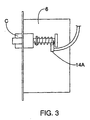
- door switch 14A is mounted in lock case 6.
- Switch 14A detects when door B has changed state, i.e. opened or closed.
- door switch 14B is used rather than door switch 14A.
- Door switch 14B can be located anywhere on the edge of door B such that when the door is separated from the door jamb the pressure switch of switch 14B is released and the switch changes state. It is preferred that door switch 14A be located in lock 2 itself such that every time the door is opened, switch 14A has a change of state and tells microcontroller 13.
- Door switch 14B is preferably wired to energy control means 1. Alternatively, switch 14B communicates with energy control means 1 in a wireless manner. Naturally, switch 14B can be mounted in door B itself or on the outside of door B.
- motion detector 15B for detecting the presence of a person in,.the room.
- motion detector 15A is mounted on wall A.
- Motion detector 15A is preferably mounted on a wall of the room in a location which allows it to view the whole room. In certain room configurations, suites or multi-roomed areas, it may be necessary or desirable to use more than one motion detector to detect the presence of the guest in the room. If motion detector 15A is employed in the present invention, it is preferably powered from the hotel, not battery-powered, and is always on.
- motion detector 15B is used in the present invention. Motion detector 15B is mounted in lock 2 on the inside and is able to view the whole room. Motion detector 15A is preferably wired to energy control means 1. Motion detector 15A can also communicate with energy control means 1 in a wireless manner such as by electromagnetic waves (radio, light, etc.).
- the motion detector is activated to detect the presence of a person in the room.
- motion detector 15A it will communicate, preferably directly to energy control means 1, as shown in FIG. 1. If the guest is detected in the room by motion detector 15B, then motion detector 15B communicates with microcontroller 13 and microcontroller 13 communicates this to energy control means 1 which in turn then operates in an occupied state and allows the temperature of the room to move to the temperature as set by the occupant-guest.
- Microcontroller 13 communicates with energy control means 1 various bits of information.
- the primary bit of information that microcontroller 13 communicates to energy control means 1 is the status of the room from sold to unsold. For example, the start time and end time or the time period of the new guest.
- microcontroller 13 also communicates changes in state for door switch 14A, i.e. opening and closing of door B.
- microcontroller 13 communicates to energy control means 1, the presence or absence of a person in the room so that the energy control means 1 moves between occupied and unoccupied states.
- energy control means 1 processes these various bits of information and controls the energy consumption of the HVAC or other electrical appliances in the room.
- FIG. 4 illustrates the flow diagram of the lock every time a card key is inserted into the lock and both the motion detector and the door switch communicate directly to the microcontroller of the lock.
- the key card has an end time or time period for the stay of the guest, this information is recorded in the lock's microcontroller so the microcontroller can communicate this information to the energy control means so that the energy control means can move from a sold mode to an unsold mode. Absent this option, hotel staff may turn the energy control means from the sold mode to the unsold mode. This is normally done when hotel staff cleans the room after the guest has checked out.
- a staff card is used to lock-out the guest after the guest has checked out of the hotel and this staff card also instructs the energy control means to move from the sold to the unsold mode.
- the energy control means can be pre-programmed to move from the sold mode to the unsold mode after a period of time since the guest card was last used.
- the motion detector is used to allow the system to move between the occupied and unoccupied modes.
- FIG. 5 illustrates the flow diagram of the lock where the motion detector communicates directly to the energy control means while the door switch communicates with the lock itself. Again, because of the motion detector, the system can operate in an occupied and unoccupied mode.
- FIG. 6 illustrates the flow diagram of the lock where both the motion detector and the door switch are connected to the energy control means.
- the lock's main function is to communicate to the energy control means the start of the sold period, and if the key card contains the end time or time period, the end time for the sold period, i.e. when to move from the sold to the unsold mode.
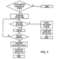
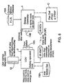
- FIG. 7 illustrates where both a motion detector and a door switch are used, the room is in the occupied mode, and the door has been opened from the inside.
- the door switch once it changes state, communicates this fact to the motion detector and the motion detector is turned on so that it can detect the presence or absence of a guest in the room.
- This change of state occurs once when the door opens and once when the door closes.
- the door switch can communicate its change of state to the motion detector each time it changes state or only once, either when it opens or when it closes.
- the motion detector can scan the room each time the door switch communicates a change of state or only once, either when the door is opened or when the door is closed.
- the motion detector must scan the room long enough to obtain an accurate determination that the room is either occupied or not occupied. Scanning can start as soon as the door is opened, first change in state of the door switch, and not end until after the door closes, the second change in state of the door switch. Alternatively, the scanning continues for a preset period of time. In one preferred embodiment,. a scanning sequence starts upon the first change of state of the door switch and continues for a preset period of time. In another preferred embodiment, a scanning sequence starts upon the second change in state of the door switch and continues for a preset period of time. In yet another preferred embodiment, a scanning sequence starts each time the door switch changes state and continues for a preset period of time. The scanning sequence is the same no matter whether a key opens the door or the door is opened from the inside of the room.
- Energy control means 1 is a conventional piece of equipment except that it has a means for communicating with lock 2. Energy control means can control not only the heating and cooling units for the room, but also all the other electrical appliances in the room such that when the guest leaves, not only does the heating and cooling unit for the room move to an unoccupied mode, but the lights, etc. are turned off.
- Energy control means 1 and lock 2 each have a means to communicate with the other.
- This means can be wire or, more preferably, is wireless, such as infrared transmission or some other electromagnetic means.
- FIG. 8 is a different embodiment of the preferred components and how they communicate with one another.
- magnetic key card 12 has the length of stay with a start time in minutes/hours/day to an end time in minutes/hours/day.
- the key card is inserted into lock 2 and the data is read off of key card 12 and communicated to energy control means 1.
- lock 2 has an infrared transmitter mounted inside escutcheon 3B of lock 2.
- Energy control means 1 has an infrared receiver which is able to receive signals from the infrared transmitter of lock 2. In this way lock 2 communicates the start and end times or sold and unsold times.
- lock 2 or energy control means 1 is connected to motion detector 15A/15B.
- lock 2 is connected to motion detector 15B, the infrared transmitter of lock 2 is used to send the necessary motion or no motion data to energy control means 1.
- lock 2 or energy control means 1 is connected to door switch 14A/14B. Where lock 2 is connected to door switch 14A, the infrared transmitter of lock 2 is used to send the change in state of the door switch to energy control means 1.
- Energy control means 1 communicates, preferably by wire, to HVAC unit C and specifically to the fan coil, the air conditioning unit, or the heating unit.
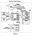
- FIG. 9 is a more detailed schematic of the lock itself.
- Lock 2 and, more specifically, microcontroller 13 is capable of allowing access to more than one card holder.
- lock 2 will open not only for a guest but also for other hotel staff and security personnel.
- Such locks are referred to as having a hierarchy system and microcontroller 13 is able to compare key codes of the different cards and allow access simultaneously to these different personnel.
- a guest will hold a guest key card and the lock will provide access to the guest if the guest key card has a key code that matches the guest access code.
- the lock will provide access to hotel staff with a staff key card if the staff key code matches the staff access code.
- the present invention has been described with reference to a hotel, it is equally applicable to ferries, cruise ships and railroad lines, as well as business offices and communal bathrooms.
- the present invention is applicable to any location where there is a user of a room and there is a desire to control the energy consumption in the room.
Landscapes
- Engineering & Computer Science (AREA)
- Chemical & Material Sciences (AREA)
- Combustion & Propulsion (AREA)
- Mechanical Engineering (AREA)
- General Engineering & Computer Science (AREA)
- Physics & Mathematics (AREA)
- General Physics & Mathematics (AREA)
- Automation & Control Theory (AREA)
- Lock And Its Accessories (AREA)
Claims (11)
- Elektronisches Schließsystem mit einem elektronischen Schloß (2), das in einer Tür eines Raumes untergebracht ist, um Zugang zu dem Raum zu erhalten; einer ersten Schlüsselkarte (12), mit einem darauf befindlichen Gästeschlüsselcode zum Öffnen des Schlosses und einer Energiesteuereinrichtung (12) zum Steuern der Temperatur innerhalb des Raumes, wobei das Schloß eine Einrichtung (13) zum Speichern eines Gästezugangscodes aufweist, ferner eine Einrichtung (13) zum Lesen des Gästeschlüsselcodes, wenn die Gästeschlüsselkarte in das Schloß eingeführt wird, eine Einrichtung (13) zum Vergleichen des Gästeschlüsselcodes mit dem Gästezugangscode, so daß, wenn der Gästeschlüsselcode mit dem Gästezugangscode übereinstimmt, das Schloß öffnet, und eine Einrichtung (13) zum direkten Kommunizieren mit der Energiesteuereinrichtung,
wobei die Energiesteuereinrichtung eine Einrichtung aufweist zum direkten Kommunizieren mit dem Schloß, und mindestens zwei Betriebsarten aufweist, nämlich eine Verkauft-Betriebsart und eine Nicht-Verkauft-Betriebsart, von denen die Nicht-Verkauft-Betriebsart einen größeren Temperaturbereich besitzt als die Verkauft-Betriebsart, dadurch gekennzeichnet, daß das Schloß eine Einrichtung (13) aufweist zum Umstellen der Energiesteuereinrichtung von der Nicht-Verkauft-Betriebsart in die Verkauft-Betriebsart, wenn die Gästeschlüsselkarte zum ersten Mal in das Schloß eingeführt wird und der Gästeschlüsselcode mit dem Gästezugangscode übereinstimmt. - Elektronisches Schließsystem nach Anspruch 1, weiterhin umfassend eine Einrichtung (15A, 15B) zum Nachweisen einer Person in dem Raum.
- Elektronisches Schließsystem nach Anspruch 2, bei dem die Nachweiseinrichtung einen an einer Wand des Raums angeordneten Detektor (15A) aufweist, der direkt mit der Energiesteuereinrichtung kommuniziert, und einen Türschalter (14A), der in der Türleibung angeordnet ist, um eine Zustandsänderung der Tür zu erkennen, wobei der Türschalter die Zustandsänderung an die Energiesteuereinrichtung übermittelt.
- Elektronisches Schließsystem nach Anspruch 2, bei dem die Nachweiseinrichtung einen Detektor (15B) aufweist, der in dem Schloß angeordnet ist, außerdem einen Türschalter (14B), der in dem Schloß gelagert ist, um eine Zustandsänderung der Tür nachzuweisen, wobei der Detektor und der Türschalter direkt mit dem Schloß kommunizieren.
- Elektronisches Schließsystem nach Anspruch 2, bei dem die Nachweiseinrichtung einen an einer Wand des Raumes angeordneten Detektor (15A) aufweist, der direkt mit der Energiesteuereinrichtung kommuniziert, weiterhin einen Türschalter (15A), der in dem Schloß angeordnet ist und direkt mit dem Schloß kommuniziert.
- Elektronisches Schließsystem nach Anspruch 1, bei dem(a) die Verkauft-Betriebsart der Energiesteuereinrichtung außerdem einen Belegt-Modus und einen Unbelegt-Modus aufweist;(b) eine Einrichtung zur Temperatureinstellung vorgesehen ist, so daß eine Person die Temperatur in dem Raum im Belegt-Modus einstellen kann, wenn die Energiesteuereinrichtung sich in der Verkauft-Betriebsart befindet; und(c) eine Nachweiseinrichtung (15a, 15b) zum Erkennen, wann sich eine Person in dem Raum befindet, vorgesehen ist, wobei die Nachweiseinrichtung eine Einrichtung aufweist zum Kommunizieren mit der Energiesteuereinrichtung derart, daß, wenn die Nachweiseinrichtung eine Person in dem Raum feststellt und sich die Energiesteuereinrichtung in der Verkauft-Betriebsart befindet, die Nachweiseinrichtung mit der Energiesteuereinrichtung kommuniziert und letztere im Belegt-Modul arbeitet, und wenn die Nachweiseinrichtung das Fehlen einer Person in dem Raum feststellt und die Energiesteuereinrichtung sich im Verkauft-Zustand befindet, die Nachweiseinrichtung mit der Energiesteuereinrichtung kommuniziert und diese im Unbelegt-Modus arbeitet.
- Elektronisches Schließsystem nach Anspruch 6, bei dem die Nachweiseinrichtung einen Detektor (15A) aufweist, der direkt mit der Energiesteuereinrichtung kommuniziert, und einen Türschalter (14A), der in der Türleibung angeordnet ist, um eine Zustandsänderung der Tür zu erkennen, wobei der Türschalter die Zustandsänderung an die Energiesteuereinrichtung übermittelt.
- Elektronisches Schließsystem nach Anspruch 6, bei dem die Nachweiseinrichtung einen Detektor (15B) aufweist, der in dem Schloß angeordnet ist, außerdem einen Türschalter (14B), der in dem Schloß gelagert ist, um eine Zustandsänderung der Tür nachzuweisen, wobei der Detektor und der Türschalter direkt mit dem Schloß kommunizieren.
- Elektronisches Schließsystem nach Anspruch 6, bei dem die Nachweiseinrichtung einen an einer Wand des Raumes angeordneten Detektor (15A) aufweist, der direkt mit der Energiesteuereinrichtung kommuniziert, weiterhin einen Türschalter (15A), der in dem Schloß angeordnet ist und direkt mit dem Schloß kommuniziert.
- Verfahren zum Steuern einer Energiesteuereinrichtung (1), die zum Steuern der Temperatur in einem Raum verwendet wird, wobei die Steuereinrichtung mindestens zwei Betriebsarten aufweist, eine Verkauft-Betriebsart und eine Nicht-Verkauft-Betriebsart, von denen die Nicht-Verkauft-Betriebsart einen größeren Temperaturbereich aufweist als die Verkauft-Betriebsart, umfassend folgende Schritte:(a) Einführen einer Gästeschlüsselkarte (12) mit einem darauf befindlichen Gästeschlüsselcode in ein elektronisches Schloß (2), das in einer Tür eines Raumes untergebracht ist, um Zugang zu dem Raum zu erhalten, so daß das Schloß den Gästeschlüsselcode von der Gästeschlüsselkarte liest, dadurch gekennzeichnet, daß das Verfahren weiterhin folgende Schritte aufweist:(b) wenn beim ersten Mal der Gästeschlüsselcode mit einem in dem Schloß gespeicherten Gästezugangscode übereinstimmt, Öffnen des Schlosses und Übermitteln an die Energiesteuereinrichtung, daß das Schloß mit der Gästeschlüsselkarte geöffnet wurde, so daß die Energiesteuereinrichtung sich von einem Nicht-Verkauft-Zustand in einen Verkauft-Zustand ändert.
- Verfahren nach Anspruch 10, weiterhin umfassend die Schritte:(a) Nachweisen des Vorhandenseins oder des Fehlens einer Person in dem Raum jedes Mal dann, wenn die Tür ihren Zustand ändert; und(b) Signalisieren des Vorhandenseins oder des Fehlens einer Person in den Raum an die Energiesteuereinrichtung.
Applications Claiming Priority (2)
| Application Number | Priority Date | Filing Date | Title |
|---|---|---|---|
| US634883 | 1996-04-19 | ||
| US08/634,883 US5933085A (en) | 1996-04-19 | 1996-04-19 | Environmental control lock system |
Publications (3)
| Publication Number | Publication Date |
|---|---|
| EP0802472A2 EP0802472A2 (de) | 1997-10-22 |
| EP0802472A3 EP0802472A3 (de) | 1997-11-05 |
| EP0802472B1 true EP0802472B1 (de) | 2002-07-24 |
Family
ID=24545542
Family Applications (1)
| Application Number | Title | Priority Date | Filing Date |
|---|---|---|---|
| EP19970400875 Expired - Lifetime EP0802472B1 (de) | 1996-04-19 | 1997-04-18 | Steuerung einer Klimaregelungsanlage durch ein Schliessystem |
Country Status (6)
| Country | Link |
|---|---|
| US (1) | US5933085A (de) |
| EP (1) | EP0802472B1 (de) |
| CN (1) | CN1164602A (de) |
| DE (1) | DE69714122D1 (de) |
| ID (1) | ID16831A (de) |
| SG (1) | SG104911A1 (de) |
Families Citing this family (44)
| Publication number | Priority date | Publication date | Assignee | Title |
|---|---|---|---|---|
| US7306262B1 (en) * | 1999-05-20 | 2007-12-11 | Electronic Forms Plus, Inc. | Single-sheet registration form and key packet |
| JP3341713B2 (ja) * | 1999-06-10 | 2002-11-05 | 日本電気株式会社 | 携帯情報カード保持機構および保持方法ならびに情報機器 |
| US6138068A (en) * | 1999-10-12 | 2000-10-24 | Liu; Jonathan | Vehicle for automatically adjusting window and sunroof positions after it being left unattended by its operator |
| EP1261895B1 (de) * | 1999-12-10 | 2005-11-23 | Sensopad Limited | Mensch-maschine interface mit relativem positionssensor |
| US6449995B1 (en) * | 2000-03-09 | 2002-09-17 | International Business Machines Corp. | Automatic deadbolt |
| GB2360606A (en) * | 2000-03-23 | 2001-09-26 | Kleenair Maintenance Services | Device for automatically controlling an air maintenance system |
| GB2382910B (en) * | 2000-08-04 | 2004-08-04 | Energy Technologies Group L L | Security and energy control system |
| JP4755804B2 (ja) * | 2000-09-26 | 2011-08-24 | パナソニック株式会社 | 対象物状態検知装置、対象物状態検知方法、家電機器、ネットワークアダプタ、及び記録媒体 |
| US7061393B2 (en) * | 2000-12-20 | 2006-06-13 | Inncom International Inc. | System and method for managing services and facilities in a multi-unit building |
| WO2002060111A2 (en) * | 2001-01-24 | 2002-08-01 | Inncom International, Inc. | Smart router for a guest room service and control system |
| US20020118095A1 (en) * | 2001-02-26 | 2002-08-29 | Lance Estes | Shared access personal storage locker apparatus, system and method |
| NL1018335C2 (nl) * | 2001-06-20 | 2002-12-30 | Heuvel Hendrikus Jozef Van Den | Werkwijze voor het schakelen van luchtbehandelingsapparatuur. |
| US6356193B1 (en) * | 2001-08-17 | 2002-03-12 | Young Chuan Liou | Self safety-protection burglarproof device |
| US6832072B2 (en) | 2001-08-31 | 2004-12-14 | Inncom International, Inc. | Wireless switch |
| US20040083128A1 (en) * | 2002-01-24 | 2004-04-29 | Buckingham Duane W. | Smart router for a guest room service and control system |
| US20030214420A1 (en) * | 2002-05-17 | 2003-11-20 | Masaru Matsui | Moving subject detecting apparatus and the method |
| JP2005240492A (ja) * | 2004-02-27 | 2005-09-08 | Oki Electric Ind Co Ltd | 鍵システム |
| US7374084B2 (en) * | 2004-06-18 | 2008-05-20 | Computerized Security Systems | Electronic lock with visual interface |
| US20060106499A1 (en) * | 2004-10-22 | 2006-05-18 | Roosli Philipp A | System and method for emergency shutdown of selected services and facilities in a multi-unit building |
| US20060292973A1 (en) * | 2005-06-24 | 2006-12-28 | Brooks Randolph F | Smoking enclosure and methods of use |
| FR2904440B1 (fr) * | 2006-07-26 | 2010-10-22 | Thermor Ind | "dispositif de chauffage de locaux" |
| US7784677B2 (en) * | 2006-09-28 | 2010-08-31 | Smart Light Tech, Llc | Apparatus for reducing energy consumption within an unoccupied room |
| KR20080073162A (ko) * | 2007-02-05 | 2008-08-08 | 엘지전자 주식회사 | 빌딩관리시스템 및 그의 운전제어방법 |
| US7659800B2 (en) * | 2007-08-01 | 2010-02-09 | Philipp Gruner | Electromagnetic relay assembly |
| US8160749B2 (en) * | 2007-12-20 | 2012-04-17 | David Donaldson | Energy conservation system |
| KR20100001474A (ko) * | 2008-06-27 | 2010-01-06 | 박세영 | 현관카드키를 이용한 전원 온/오프시스템 |
| US8009042B2 (en) | 2008-09-03 | 2011-08-30 | Lutron Electronics Co., Inc. | Radio-frequency lighting control system with occupancy sensing |
| US9277629B2 (en) | 2008-09-03 | 2016-03-01 | Lutron Electronics Co., Inc. | Radio-frequency lighting control system with occupancy sensing |
| US8184004B2 (en) * | 2009-01-29 | 2012-05-22 | Inncom International Inc. | System to detect presence in a space |
| WO2010116391A1 (en) * | 2009-04-09 | 2010-10-14 | Cisa S.P.A. | Management and control unit for inner spaces of buildings |
| CN101894402A (zh) * | 2009-05-20 | 2010-11-24 | 鸿富锦精密工业(深圳)有限公司 | 智能控制系统 |
| US8988190B2 (en) * | 2009-09-03 | 2015-03-24 | Dell Products, Lp | Gesture based electronic latch for laptop computers |
| WO2011109460A2 (en) | 2010-03-02 | 2011-09-09 | Liberty Plug-Ins, Inc. | Method and system for using a smart phone for electrical vehicle charging |
| US8902040B2 (en) | 2011-08-18 | 2014-12-02 | Greisen Enterprises Llc | Electronic lock and method |
| US8622297B1 (en) * | 2012-05-14 | 2014-01-07 | Citigroup Technology, Inc. | Card reader anti-skimming assembly and method |
| US10591201B2 (en) | 2013-01-18 | 2020-03-17 | Triteq Lock And Security, Llc | Cooler lock |
| US9818288B2 (en) | 2014-01-31 | 2017-11-14 | Trane International Inc. | HVAC system with visitor presence sensor |
| CN103837906B (zh) * | 2014-03-13 | 2016-12-07 | 三和智控(北京)系统集成有限公司 | 一种探测房间内是否有人的方法 |
| US9284755B2 (en) * | 2014-07-10 | 2016-03-15 | Ingenuity Automotive, LLC | System for remotely checking locked status of a vehicle |
| US20160069582A1 (en) * | 2014-09-08 | 2016-03-10 | Trane International Inc. | HVAC System with Motion Sensor |
| US10848334B2 (en) | 2016-08-30 | 2020-11-24 | Dwelo Inc. | Automatic transitions in automation settings |
| US10247429B2 (en) | 2017-05-18 | 2019-04-02 | Haier Us Appliance Solutions, Inc. | System and method for determining the position of a vent door of a packaged terminal air conditioner unit |
| CN109025531B (zh) * | 2018-08-02 | 2023-07-25 | 王力安防科技股份有限公司 | 用于智能门锁的锁芯结构、智能门锁和防盗门 |
| US11639617B1 (en) | 2019-04-03 | 2023-05-02 | The Chamberlain Group Llc | Access control system and method |
Family Cites Families (9)
| Publication number | Priority date | Publication date | Assignee | Title |
|---|---|---|---|---|
| US4101886A (en) * | 1977-05-16 | 1978-07-18 | Grimes Johnny C | Apparatus for conserving energy in electrical appliances |
| US4485864A (en) * | 1981-01-14 | 1984-12-04 | Flair-Emsco Corporation | Occupancy responsive temperature control system |
| US4534194A (en) * | 1981-03-16 | 1985-08-13 | Kadex, Incorporated | Electronic lock system |
| US4717816A (en) * | 1984-02-13 | 1988-01-05 | Raymond James W | Electronic lock and key system for hotels and the like |
| GB8612467D0 (en) * | 1986-05-22 | 1986-07-02 | Unisafe Ltd | Electronic locking devices |
| ES2070045B1 (es) * | 1992-11-04 | 1997-03-01 | Talleres Escoriaza Sa | Nueva cerradura electronica programable. |
| US5591950A (en) * | 1992-11-04 | 1997-01-07 | Talleres De Escoriaza, S.A. (Tesa) | Programmable electronic lock |
| US5476221A (en) * | 1994-01-28 | 1995-12-19 | Seymour; Richard L. | Easy-to-install thermostatic control system based on room occupancy |
| FR2723658B1 (fr) * | 1994-08-10 | 1996-10-31 | Electroniques Sf2E Soc Fr Et | Installation de gestion d'energie et de controle d'acces d'un local |
-
1996
- 1996-04-19 US US08/634,883 patent/US5933085A/en not_active Expired - Fee Related
-
1997
- 1997-04-03 SG SG9701037A patent/SG104911A1/en unknown
- 1997-04-18 CN CN97103798A patent/CN1164602A/zh active Pending
- 1997-04-18 DE DE69714122T patent/DE69714122D1/de not_active Expired - Lifetime
- 1997-04-18 EP EP19970400875 patent/EP0802472B1/de not_active Expired - Lifetime
- 1997-04-21 ID ID971305A patent/ID16831A/id unknown
Also Published As
| Publication number | Publication date |
|---|---|
| CN1164602A (zh) | 1997-11-12 |
| EP0802472A3 (de) | 1997-11-05 |
| US5933085A (en) | 1999-08-03 |
| EP0802472A2 (de) | 1997-10-22 |
| DE69714122D1 (de) | 2002-08-29 |
| ID16831A (id) | 1997-11-13 |
| SG104911A1 (en) | 2004-07-30 |
Similar Documents
| Publication | Publication Date | Title |
|---|---|---|
| EP0802472B1 (de) | Steuerung einer Klimaregelungsanlage durch ein Schliessystem | |
| US5670940A (en) | Electronic lock system with occupancy block | |
| US7421247B2 (en) | Wireless switch | |
| US7446644B2 (en) | Universal hands free key and lock system | |
| US5476221A (en) | Easy-to-install thermostatic control system based on room occupancy | |
| US7043060B2 (en) | Fingerprint-actuated padlock | |
| HK1250827A1 (zh) | 用於家具、橱柜或储物柜的电子锁和电子锁定系统 | |
| GB2251266A (en) | Coded lock/key system with override | |
| JP4828262B2 (ja) | ロックシステム | |
| US4868914A (en) | Method for clearing unlocking key codes in an electronic locking device | |
| KR101944882B1 (ko) | 공조, 조명, 설비 제어를 이용한 에너지 절감형 출입통제 시스템 및 그의 공조, 조명 제어 방법 | |
| KR102161199B1 (ko) | 도어록을 이용한 시설 관리시스템 | |
| US4189692A (en) | Lock controlled power shut-off system | |
| EP0250101B1 (de) | Elektronische Verschlussvorrichtungen | |
| JP2005141394A (ja) | セキュリティシステム | |
| JP4488495B2 (ja) | 入退室管理システム | |
| JP2003161066A (ja) | 情報読取機能付錠 | |
| JP2009138464A (ja) | 電気錠システム用アダプタ | |
| JPH0747906B2 (ja) | エントランス・チエツカ− | |
| JP3422538B2 (ja) | カードロックシステム | |
| EP0246903A1 (de) | Verfahren zum Löschen von Entriegelungskoden in einer elektronischen Verriegelungsvorrichtung | |
| JPH055374A (ja) | 磁気カードシステム | |
| JPS5854831A (ja) | ホテル等における室内電源制御方式 | |
| JPH0311175B2 (de) | ||
| JPH0334097A (ja) | 侵入監視装置 |
Legal Events
| Date | Code | Title | Description |
|---|---|---|---|
| PUAI | Public reference made under article 153(3) epc to a published international application that has entered the european phase |
Free format text: ORIGINAL CODE: 0009012 |
|
| PUAL | Search report despatched |
Free format text: ORIGINAL CODE: 0009013 |
|
| 17P | Request for examination filed |
Effective date: 19970805 |
|
| AK | Designated contracting states |
Kind code of ref document: A2 Designated state(s): DE ES GB IT |
|
| AK | Designated contracting states |
Kind code of ref document: A3 Designated state(s): AT BE CH DE DK ES FI FR GB GR IE IT LI LU MC NL PT SE |
|
| RBV | Designated contracting states (corrected) |
Designated state(s): DE ES GB IT |
|
| RAP1 | Party data changed (applicant data changed or rights of an application transferred) |
Owner name: VINGCARD A.S. |
|
| 17Q | First examination report despatched |
Effective date: 19991202 |
|
| GRAG | Despatch of communication of intention to grant |
Free format text: ORIGINAL CODE: EPIDOS AGRA |
|
| GRAG | Despatch of communication of intention to grant |
Free format text: ORIGINAL CODE: EPIDOS AGRA |
|
| GRAH | Despatch of communication of intention to grant a patent |
Free format text: ORIGINAL CODE: EPIDOS IGRA |
|
| GRAH | Despatch of communication of intention to grant a patent |
Free format text: ORIGINAL CODE: EPIDOS IGRA |
|
| GRAA | (expected) grant |
Free format text: ORIGINAL CODE: 0009210 |
|
| AK | Designated contracting states |
Kind code of ref document: B1 Designated state(s): DE ES GB IT |
|
| PG25 | Lapsed in a contracting state [announced via postgrant information from national office to epo] |
Ref country code: IT Free format text: LAPSE BECAUSE OF FAILURE TO SUBMIT A TRANSLATION OF THE DESCRIPTION OR TO PAY THE FEE WITHIN THE PRESCRIBED TIME-LIMIT;WARNING: LAPSES OF ITALIAN PATENTS WITH EFFECTIVE DATE BEFORE 2007 MAY HAVE OCCURRED AT ANY TIME BEFORE 2007. THE CORRECT EFFECTIVE DATE MAY BE DIFFERENT FROM THE ONE RECORDED. Effective date: 20020724 |
|
| REG | Reference to a national code |
Ref country code: GB Ref legal event code: FG4D |
|
| REF | Corresponds to: |
Ref document number: 69714122 Country of ref document: DE Date of ref document: 20020829 |
|
| PG25 | Lapsed in a contracting state [announced via postgrant information from national office to epo] |
Ref country code: DE Free format text: LAPSE BECAUSE OF FAILURE TO SUBMIT A TRANSLATION OF THE DESCRIPTION OR TO PAY THE FEE WITHIN THE PRESCRIBED TIME-LIMIT Effective date: 20021025 |
|
| PG25 | Lapsed in a contracting state [announced via postgrant information from national office to epo] |
Ref country code: ES Free format text: LAPSE BECAUSE OF FAILURE TO SUBMIT A TRANSLATION OF THE DESCRIPTION OR TO PAY THE FEE WITHIN THE PRESCRIBED TIME-LIMIT Effective date: 20030130 |
|
| PLBE | No opposition filed within time limit |
Free format text: ORIGINAL CODE: 0009261 |
|
| STAA | Information on the status of an ep patent application or granted ep patent |
Free format text: STATUS: NO OPPOSITION FILED WITHIN TIME LIMIT |
|
| 26N | No opposition filed |
Effective date: 20030425 |
|
| PGFP | Annual fee paid to national office [announced via postgrant information from national office to epo] |
Ref country code: GB Payment date: 20050411 Year of fee payment: 9 |
|
| PG25 | Lapsed in a contracting state [announced via postgrant information from national office to epo] |
Ref country code: GB Free format text: LAPSE BECAUSE OF NON-PAYMENT OF DUE FEES Effective date: 20060418 |
|
| GBPC | Gb: european patent ceased through non-payment of renewal fee |
Effective date: 20060418 |