EP0802427A2 - Procédé à coût réduit pour la détermination de la réponse impulsionelle d'un canal radar à bande limitée et haute résolution - Google Patents
Procédé à coût réduit pour la détermination de la réponse impulsionelle d'un canal radar à bande limitée et haute résolution Download PDFInfo
- Publication number
- EP0802427A2 EP0802427A2 EP97106431A EP97106431A EP0802427A2 EP 0802427 A2 EP0802427 A2 EP 0802427A2 EP 97106431 A EP97106431 A EP 97106431A EP 97106431 A EP97106431 A EP 97106431A EP 0802427 A2 EP0802427 A2 EP 0802427A2
- Authority
- EP
- European Patent Office
- Prior art keywords
- radar
- channel
- received signal
- optimal
- impulse response
- Prior art date
- Legal status (The legal status is an assumption and is not a legal conclusion. Google has not performed a legal analysis and makes no representation as to the accuracy of the status listed.)
- Granted
Links
Images


Classifications
-
- G—PHYSICS
- G01—MEASURING; TESTING
- G01S—RADIO DIRECTION-FINDING; RADIO NAVIGATION; DETERMINING DISTANCE OR VELOCITY BY USE OF RADIO WAVES; LOCATING OR PRESENCE-DETECTING BY USE OF THE REFLECTION OR RERADIATION OF RADIO WAVES; ANALOGOUS ARRANGEMENTS USING OTHER WAVES
- G01S13/00—Systems using the reflection or reradiation of radio waves, e.g. radar systems; Analogous systems using reflection or reradiation of waves whose nature or wavelength is irrelevant or unspecified
- G01S13/02—Systems using reflection of radio waves, e.g. primary radar systems; Analogous systems
- G01S13/06—Systems determining position data of a target
- G01S13/08—Systems for measuring distance only
- G01S13/10—Systems for measuring distance only using transmission of interrupted, pulse modulated waves
- G01S13/26—Systems for measuring distance only using transmission of interrupted, pulse modulated waves wherein the transmitted pulses use a frequency- or phase-modulated carrier wave
- G01S13/28—Systems for measuring distance only using transmission of interrupted, pulse modulated waves wherein the transmitted pulses use a frequency- or phase-modulated carrier wave with time compression of received pulses
- G01S13/284—Systems for measuring distance only using transmission of interrupted, pulse modulated waves wherein the transmitted pulses use a frequency- or phase-modulated carrier wave with time compression of received pulses using coded pulses
-
- G—PHYSICS
- G01—MEASURING; TESTING
- G01S—RADIO DIRECTION-FINDING; RADIO NAVIGATION; DETERMINING DISTANCE OR VELOCITY BY USE OF RADIO WAVES; LOCATING OR PRESENCE-DETECTING BY USE OF THE REFLECTION OR RERADIATION OF RADIO WAVES; ANALOGOUS ARRANGEMENTS USING OTHER WAVES
- G01S7/00—Details of systems according to groups G01S13/00, G01S15/00, G01S17/00
- G01S7/02—Details of systems according to groups G01S13/00, G01S15/00, G01S17/00 of systems according to group G01S13/00
- G01S7/40—Means for monitoring or calibrating
-
- G—PHYSICS
- G01—MEASURING; TESTING
- G01S—RADIO DIRECTION-FINDING; RADIO NAVIGATION; DETERMINING DISTANCE OR VELOCITY BY USE OF RADIO WAVES; LOCATING OR PRESENCE-DETECTING BY USE OF THE REFLECTION OR RERADIATION OF RADIO WAVES; ANALOGOUS ARRANGEMENTS USING OTHER WAVES
- G01S13/00—Systems using the reflection or reradiation of radio waves, e.g. radar systems; Analogous systems using reflection or reradiation of waves whose nature or wavelength is irrelevant or unspecified
- G01S13/003—Bistatic radar systems; Multistatic radar systems
-
- G—PHYSICS
- G01—MEASURING; TESTING
- G01S—RADIO DIRECTION-FINDING; RADIO NAVIGATION; DETERMINING DISTANCE OR VELOCITY BY USE OF RADIO WAVES; LOCATING OR PRESENCE-DETECTING BY USE OF THE REFLECTION OR RERADIATION OF RADIO WAVES; ANALOGOUS ARRANGEMENTS USING OTHER WAVES
- G01S13/00—Systems using the reflection or reradiation of radio waves, e.g. radar systems; Analogous systems using reflection or reradiation of waves whose nature or wavelength is irrelevant or unspecified
- G01S13/87—Combinations of radar systems, e.g. primary radar and secondary radar
-
- G—PHYSICS
- G01—MEASURING; TESTING
- G01S—RADIO DIRECTION-FINDING; RADIO NAVIGATION; DETERMINING DISTANCE OR VELOCITY BY USE OF RADIO WAVES; LOCATING OR PRESENCE-DETECTING BY USE OF THE REFLECTION OR RERADIATION OF RADIO WAVES; ANALOGOUS ARRANGEMENTS USING OTHER WAVES
- G01S13/00—Systems using the reflection or reradiation of radio waves, e.g. radar systems; Analogous systems using reflection or reradiation of waves whose nature or wavelength is irrelevant or unspecified
- G01S13/88—Radar or analogous systems specially adapted for specific applications
- G01S13/93—Radar or analogous systems specially adapted for specific applications for anti-collision purposes
- G01S13/933—Radar or analogous systems specially adapted for specific applications for anti-collision purposes of aircraft or spacecraft
- G01S13/934—Radar or analogous systems specially adapted for specific applications for anti-collision purposes of aircraft or spacecraft on airport surfaces, e.g. while taxiing
-
- G—PHYSICS
- G01—MEASURING; TESTING
- G01S—RADIO DIRECTION-FINDING; RADIO NAVIGATION; DETERMINING DISTANCE OR VELOCITY BY USE OF RADIO WAVES; LOCATING OR PRESENCE-DETECTING BY USE OF THE REFLECTION OR RERADIATION OF RADIO WAVES; ANALOGOUS ARRANGEMENTS USING OTHER WAVES
- G01S7/00—Details of systems according to groups G01S13/00, G01S15/00, G01S17/00
- G01S7/02—Details of systems according to groups G01S13/00, G01S15/00, G01S17/00 of systems according to group G01S13/00
- G01S7/41—Details of systems according to groups G01S13/00, G01S15/00, G01S17/00 of systems according to group G01S13/00 using analysis of echo signal for target characterisation; Target signature; Target cross-section
Definitions
- the invention relates to a method for the cost-effective determination of an impulse response of a high-resolution band-limited radar channel according to the preamble of claim 1.
- NR short-range radar
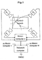
- the individual radar stations have fixed, ie non-rotating antennas that are installed in such a way that reflections and shadows on buildings are minimal.
- the fixed antennas which together illuminate a control area K to be monitored, have an extremely large, horizontal opening angle.
- pulse compression signals ie time-expanded pulses
- time-bandwidth Have a product much larger than one.
- the individual radar stations R i of a module or the radar stations of different modules do not interfere with one another, the individual radar stations of the entire NR network transmit at the same time. Furthermore, all radar stations transmit in the same frequency band, preferably in the X-band, with a measurement repetition frequency of 100 Hz.
- the measurement data of the individual measurement stations R i are collected and processed by a module computer.
- the module computer uses one-dimensional echo profiles, which are measured by the individual radar stations, to calculate the positions of moving objects in the control area to be monitored. Since only radial distances are measured, the location of an object follows from the intersection of intersecting circular arcs around the radar stations R i (see FIG. 1).
- SMGC Surface Movement Guidance and Control
- Complementary codes are code pairs that are constructed in such a way that the linear correlation maxima cancel each other out when the autocorrelation functions are added linearly in pairs.
- the individual codes, which form a complementary code pair are transmitted one after the other and fed to the appropriate signal-matched filters in the receiver.
- the desired compensation of secondary maxima can then be achieved by in-phase linear addition of the signals at the output of the matched filters.
- receivers that work with signal-adapted filtering are known to have difficulties if, on the one hand, as in a radar system, the initial phases of the echo signals in the receiver are not exactly known, and on the other hand Doppler shifts occur. In these cases, compensation of secondary maxima does not occur to an extent sufficient for this application.
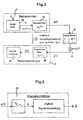
- a binary-phase-coded, expanded transmission pulse is generated digitally by the binary code elements c i ⁇ [-1, + 1] of the binary code the length N is read from a digital memory 10 at a time interval T c (chip duration) and fed to a transmission filter 11 with the impulse response h s ( ⁇ ).
- the transmission behavior of the radar channel 2 can be completely described by its channel impulse response h ( ⁇ ).
- the signal r ⁇ (t) - ⁇ + ⁇ a ⁇ (t- ⁇ ) H ⁇ ( ⁇ ) d ⁇ + n ⁇ e (t) at the receiver input, to which additive noise n e (t) is superimposed, a reception filter 30 with the impulse response h e ( ⁇ ) fed.
- the most precise possible estimate of the impulse response of the radar channel 2 can be determined from the received signal e (t) according to Eq. (7) and by using any kind of a priori knowledge. Since the radar channel impulse response is determined by the reflecting objects present in the radar channel, the information aimed at in a radar system about the location, speed and type of the reflecting objects in the radar channel 2 can be determined by interpreting the estimated radar channel impulse response.
- measurable channel impulse response can be determined according to Eq. (5).
- the transmission filter 11 and the reception filter 30 must therefore be selected accordingly so that information about the reflecting objects in the radar channel 2 can be obtained in a simple manner from the measurable channel impulse response x ( ⁇ ).
- the received signal e (t) is sampled according to Eq. (7). Since only M distance gates are of interest, the measurable channel impulse response is only within a time interval 0 ⁇ ⁇ ⁇ (M-1) T c evaluated.
- the received signal e (t) is only within the time interval 0 ⁇ t ⁇ (M + N-1) T c influenced by the relevant range of the measurable channel impulse response x ( ⁇ ) according to Eq. (8).
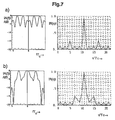
- the widely used principle of digital, receiver-side signal processing of expanded pulses is the correlation based on the signal-adapted filtering.
- the received signal e according to Eq. (12) is correlated with the time-inverse and conjugate complex expanded transmission pulse c according to Eq. (2).
- the estimate MF of the channel impulse response x at the output of a matched filter is obtained by multiplying the received signal e according to Eq. (12) by the matrix A * T , ie
- the autocorrelation function of the transmit pulse is obtained at its output, which consists of the main correlation peak, which is also referred to as a compressed pulse, and of smaller correlation secondary maxima.
- the correlation secondary maxima at the filter output that are unavoidable in the case of signal-adapted filtering are very disruptive, since they mask main correlation peaks due to smaller targets ( ⁇ loss of detection) or correlation main peaks can fake non-existent destinations ( ⁇ false alarm).
- an optimal, true-to-life channel estimator is completely characterized by the estimation matrix S.
- the absolute greatest matrix elements S ij typically in a band of width N concentrated around the main diagonal of the estimation matrix S may not be neglected in a dynamic range requirement of 40 to 50 dB, the magnitude small matrix elements S ij outside this band.
- the estimation matrix S of an optimal, true-to-expect channel estimator is determined exclusively by the expanded transmission pulse c according to Eq. (2). Since the expanded transmission pulse c is known in the receiver 3, the estimation matrix S can theoretically be calculated offline a priori and stored in the receiver 3.
- NR modular short-range radar
- an optimal method for determining an impulse response of a radar channel with high resolution in the radar stations is e.g. of a modular NR network.
- a matrix B can be inverted particularly inexpensively if the matrix B is circulating to the right, ie if it applies
- the modified, true-to-expect channel estimator according to Eq. (19) is thus characterized by an estimation matrix A E -1 .
- the transformation matrix T which transforms the matrix A E into a diagonal matrix
- DFT discrete Fourier transform
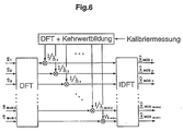
- the modified, true-to-expect channel estimator as shown in Fig. 6, can be realized.
- the discrete Fourier transform T DFT e of the received signal e according to Eq. (18) or Eq. (12) is formed in a first step I.
- DF discrete Fourier
- the vector ⁇ according to Eq. 21) to be replaced by the DF transformation of the effective, expanded pulse measured in the calibration measurement in the receiver. If the modified true-to-life channel estimation according to FIG. 6 is implemented, there is no need after every calibration measurement the matrix A E are inverted according to Eq. (16), but only the DF transformation of the effective, expanded pulse recorded during the calibration measurement and expanded according to Eq. (21) is calculated.
- the modified, true-to-expect channel estimator can be realized for such expanded pulses c for which all amounts
- (i 1 ... N) of the discrete Fourier transform ⁇ equal to T DFT c E according to Eq. (21) are different from zero.
- an estimate that is true to expectations is generated on the basis of a reflecting object in the radar channel x ⁇ ⁇ OSi or x ⁇ ⁇ Obtain MOSi for the reflectivity x i of this object.
- systematic errors that can be compared to secondary correlation maxima at the output of a signal-adapted filter are avoided from the outset when the channel estimate is true to expectations. If the received signal e according to Eq. (12) contains the additive noise n according to Eq. (10), then additive noise is also obtained at the output of an expected channel estimator, the power of which, however, is always greater than the power of the additive noise at the output of a matched filter.
- the SN ratio at the output of the true channel estimator is lower by an SNR degradation d OS or d MOS .
- both d OS according to Eq. (30) and d MOS according to Eq. (31) depend on the expanded transmission pulse c according to Eq. (2) and the number M of the distance gates under consideration. Extensive investigations have shown, however, that the influence of the parameter M on the SNR degradations d OS and d MOS according to Eqs. (30) and (31) for M >> N and with a suitable choice of the expanded transmission pulse c is negligible . Furthermore, the SNR degradation d MOS of the modified, cost-effectively implementable, accurate channel estimator is always greater than the SNR degradation d OS of the optimal, reliable channel estimator.
- the SNR degradation d MOS is determined exclusively by the amounts
- of the elements ⁇ i (i 1 ... M + N-1) of the DF transform ⁇ of the expanded expanded transmission pulse c E according to Eq. (21), which means that the small values ⁇ i for SNR degradation d MOS are the largest Contribute.
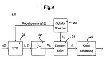
- the STC unit used in the receiver devices of the individual radar stations of the NR network is a time-variable amplifier arrangement with which the influence of the radio field attenuation is compensated. This STC unit also ensures that the sensitivity of the receiver is not undercut, even with very weak echo signals.
- the control voltage of the STC is stored digitally in the receiver and can thus be used as a priori knowledge in the digital receiver signal processing.
- the relative dynamics within an echo profile is defined below in the case of compensated radio field attenuation as the maximum ratio of the amounts of two reflectivities detectable from the estimated channel impulse response of the radar channel. If the channel estimate is true to expectations, the achievable dynamics can only be achieved through the additive noise due to the previously avoided correlation secondary maxima, i.e. with a fixed SNR at the receiver input and a predetermined code length N through the SNR degradation d OS or d MOS according to Eq. (30) or Eq . (31) limited. Minimum or very low SNR degradations are achieved with the binary codes in FIG. 8, which is why the binary codes shown in FIG. 8 are particularly well suited for a receiver concept with channel estimation that is true to expectations.
- the STC unit implemented in the receiving devices of the radar stations of the NR network is an amplifier unit with amplification that changes over time.
- the control voltage of the STC unit is selected so that the influence of the radio field attenuation is compensated, i.e. Echo signals due to reflective objects near the radar antenna are attenuated, while echo signals due to reflective objects are amplified at the outer limit of the control area of the NRN module.
- the STC unit is also necessary to avoid falling below the limit sensitivity of the receiver.
- the course of the control voltage over time is stored digitally in the receiver. Regardless of the type of signal processing on the receiver side for channel estimation, the influence of the STC unit must be compensated for after the digitization of the received signal.
- the received signal e (t) according to Eq. (7) is first fed to the STC unit 21.
- the influence of the STC unit 21 can be compensated again after the digitization of the signal e k (t).
- a compensation device 24 of Fig.9 e (12) k in Eq. (33) the vector s according to Eq from the vector. Pursuant educated. It can be seen from Eq. (34) that the compensation of the influence of the STC unit must be carried out independently of the type of signal processing on the receiver side for channel estimation. The actual channel estimation then takes place in a channel estimator 25.
- an expanded transmission pulse a (t) with the carrier frequency f o is reflected at a moving target with the radial speed v r to the radar antenna, then the carrier frequency f o of the reflected echo signal is around the Doppler frequency shifted, where c o is the speed of light.
- the carrier frequency of the expanded transmission pulse reflected at a moving target is increased by the Doppler frequency f d according to Eq. (35) when the target moves towards the radar antenna and decreased by the Doppler frequency f d when the target moves away from the radar antenna.
- the Doppler frequency f d according to Eq. (35)
- the complex reflectivity of a moving target with the radial velocity v ri in the i-th range gate applies
- the received signal at the associated radar stations is equal to the sum of time-shifted and Doppler-shifted versions of the expanded transmission pulse, weighted with the complex reflectivities x i .
- the estimation matrix ( A ⁇ * T A) ⁇ -1 A ⁇ * T characterized, optimal, true-to-expect channel estimators approximating the received signal by a sum of time-shifted and weighted versions of the transmitted, not Doppler-shifted expanded pulse c in the sense of smallest squares of errors is the estimate OS according to Eq. (14) at the output of the optimal, true-to-expect channel estimator or the estimate MOS according to Eq. (19) at the output of the modified expected channel estimator is no longer true to expectations when the received signal is shifted Doppler.
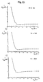
- 0 dB in the middle of the channel).
- the chip duration T c is 14 ns and the transmission frequency f o is 10 GHz.
- the systematic estimation errors increase with increasing Doppler shift f d (Fig. 10).
- Equation (37) introduced the quotient v (f d ) as a measure of quality for evaluating the systematic estimation errors at the output of an expected channel estimator with different Doppler shifts f d , which is a direct measure of the relative dynamics that can be achieved with a large SNR within an echo profile.
- 11 shows the quality measure v (f d ) in dB according to Eq. (37), which is plotted against the Doppler shift f d in Hz for the optimized binary codes of length N equal to 16, 32 and 64.
- the equidistant rectangle adjustment is considered below; during the quantization, the sampled values e Ii and e Qi of the quadrature components e I (t) and e Q (t) of the received signal e (t) according to Eq. (7) become two similar M R- stage quantizers with the quantization word width m e / bit equal to ld (M R ), whose transmission behavior has a zero-point-symmetrical characteristic with equidistant threshold distances.
- the quantized samples Q ( e i ) according to Eq. (38) are represented by binary code words of length m e / bit.
- the signal processing steps, sampling, quantization and binary coding together are also referred to as analog-to-digital conversion.
- the elements of the estimation matrix that fully characterize a channel estimator that is true to expectations can only be stored in a digital memory in the receiver with a finite word length m M / bit.
- the basic structure of the receiver of a digital system with channel estimation according to FIG. 12 is considered.
- a microprocessor or a d igital S ignal p ROCESSOR may be employed, whose internal Word widths are significantly larger than the word widths m e or m M.
- the channel estimates become OS or MOS according to Eq. (14) or Eq. (19) increasingly falsified by the quantization error.
- a small word width m e of the AD converter on the receiver side is advantageous in that the complexity of an AD converter increases sharply with increasing word width.
- a small word width m M is advantageous since the size of the digital memory required for storing the estimation matrix and the data transfer required for channel estimation between the digital memory and the digital arithmetic unit increases with increasing word width m M.
- the quality measure V is a measure of the relative dynamics within an echo profile that can be achieved depending on the word widths m M and m e in a noise-free case.
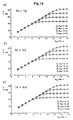
- Fig. 13a to c the SNR degradation d OS of an optimal expectant channel estimator is plotted over the word width m M / bit for the optimized binary codes of length N equal to 16, 32 and 64.
- the quality measure V according to Eq. (39) is in turn plotted for the optimized binary codes of length N equal to 16, 32 and 64 for different word widths m e .
- 14a to 14c shows that for m M ⁇ m e with increasing word width m M a dynamic increase of 6 dB / bit is achieved.
- Optimal estimation dynamics are achieved if m M is chosen equal to m e , since for m e > m M the estimation errors limit the estimation dynamics due to the finite word width m M and even with word widths m M > m e no increase in the estimation dynamics can be achieved.
- both the word length m e and the word width m M must be selected to be greater than 8 bits.
- a target with a radar cross section of 1 m 2 can be detected at a distance of 1000 m with a transmission line of 1 W.
- the SNR at the receiver input is approx. - 25dB.
- a target detection is therefore only possible if a process gain p of at least 25 dB is reached.
- the process gain p achievable by the signal processing on the receiver side is in accordance with the sum of a process gain p OS of the channel estimator which is true to expectations and a process gain p i achieved by coherent pulse integration.
- the equations (27) and (28) and the SNR degradation d OS according to FIG. 8 result in the process gains p OS listed in Table 2 below for the optimized binary codes of length N equal to 16, 32 and 64.
- Each radar station should transmit binary-phase-coded, expanded pulses of the duration N ⁇ T c with a time interval T r , where T r >> N ⁇ T c applies.
- the process gain p i which can be achieved by coherent integration is defined as the ratio of the SNR ⁇ aK at the output of the channel estimator after K integration steps to the SNR ⁇ a1 at the output of the channel estimator without coherent integration, ie
- the process gain p i according to Eq. (41) increases accordingly with increasing number K of the integration steps.
- any desired process gain p i according to Eq. (41) can theoretically be achieved by coherent integration according to Eq. (42).
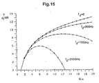
- the process gain achievable by coherent integration is always smaller than the process gain according to Eq. (42), ie since, due to the non-vanishing Doppler shifts, the phases of the useful signal components to be integrated are not the same, so that there is no completely constructive overlay.
- the product f dmax ⁇ T r from the maximum Doppler shift f dmax and the pulse repetition duration T r has a decisive influence on the maximum process gain p imax that can be achieved through coherent integration .
- the smaller f dmax ⁇ T r the greater the process gain p imax . Since the maximum expected Doppler shift in the NR network under consideration is equal to 2000 Hz, the choice of the pulse repetition duration T r is of particular importance.
- T r is chosen small, a large process gain p i can be achieved on the one hand through coherent integration, but on the other hand a serious overreach problem arises in the receiver.
- the overreach problem is that during the active period of the receiver, not only echo signals due to the expanded pulse sent immediately before, but also echo signals from reflecting objects in overreach due to expansion pulses not sent immediately before are received.
- the overreach problem is solved in a natural way if the pulse repetition duration T r is chosen so large that echo signals from reflecting objects in overreach due to an expanded transmit pulse have decayed before the subsequent expanded transmit pulse is transmitted. With the NR network, reflecting objects up to a maximum distance of 4500m are considered relevant. If the pulse repetition duration T r is at least 30 ⁇ s, the overreaching is no longer important.
- Table 3 T r / ⁇ s f d / Hz p imax / dB K opt 30th 500 11.87 25th 30th 1000 8.87 12 30th 2000 5.90 6 10th 2000 10.62 19th 20th 2000 7.63 9 40 2000 4.66 5
Landscapes
- Engineering & Computer Science (AREA)
- Radar, Positioning & Navigation (AREA)
- Remote Sensing (AREA)
- Computer Networks & Wireless Communication (AREA)
- Physics & Mathematics (AREA)
- General Physics & Mathematics (AREA)
- Radar Systems Or Details Thereof (AREA)
Applications Claiming Priority (2)
| Application Number | Priority Date | Filing Date | Title |
|---|---|---|---|
| DE19615353A DE19615353C2 (de) | 1996-04-18 | 1996-04-18 | Verfahren zum aufwandgünstigen Bestimmen einer Impulsantwort eines hochauflösenden bandbegrenzten Radarkanals |
| DE19615353 | 1996-04-18 |
Publications (3)
| Publication Number | Publication Date |
|---|---|
| EP0802427A2 true EP0802427A2 (fr) | 1997-10-22 |
| EP0802427A3 EP0802427A3 (fr) | 1998-08-05 |
| EP0802427B1 EP0802427B1 (fr) | 2000-03-08 |
Family
ID=7791661
Family Applications (1)
| Application Number | Title | Priority Date | Filing Date |
|---|---|---|---|
| EP97106431A Expired - Lifetime EP0802427B1 (fr) | 1996-04-18 | 1997-04-18 | Procédé à coût réduit pour la détermination de la réponse impulsionelle d'un canal radar à bande limitée et haute résolution |
Country Status (4)
| Country | Link |
|---|---|
| US (1) | US5805107A (fr) |
| EP (1) | EP0802427B1 (fr) |
| DE (1) | DE19615353C2 (fr) |
| ES (1) | ES2145532T3 (fr) |
Cited By (4)
| Publication number | Priority date | Publication date | Assignee | Title |
|---|---|---|---|---|
| WO2015078960A1 (fr) * | 2013-11-29 | 2015-06-04 | Siemens Aktiengesellschaft | Procédé de détection pour la localisation d'une particule, et dispositif pour la mise en œuvre d'un tel procédé |
| US11032724B2 (en) | 2019-07-10 | 2021-06-08 | Rohde & Schwarz Gmbh & Co. Kg | System and method for optimizing signal path calibration |
| CN114428229A (zh) * | 2022-01-02 | 2022-05-03 | 西安电子科技大学 | 任意时间间隔脉冲编码雷达的信噪比提升方法 |
| CN118444346A (zh) * | 2024-05-06 | 2024-08-06 | 深圳技术大学 | 一种基于快速frft的超分辨精细采集方法 |
Families Citing this family (15)
| Publication number | Priority date | Publication date | Assignee | Title |
|---|---|---|---|---|
| FI106656B (fi) | 1998-03-26 | 2001-03-15 | Markku Sakari Lehtinen | Menetelmä ja järjestelmä tutkaheijastavuuden ja doppler-siirtymän mittaamiseksi pulssitutkalla |
| DE19910715C2 (de) * | 1999-03-10 | 2002-09-26 | Deutsch Zentr Luft & Raumfahrt | Verfahren zum autonomen Führen von Roboterfahrzeugen in Hallen sowie Radarstation zur Durchführung des Verfahrens |
| US6680969B1 (en) * | 1999-03-22 | 2004-01-20 | Ericsson, Inc. | Methods for estimating doppler spreads including autocorrelation function hypotheses and related systems and receivers |
| FR2803467B1 (fr) * | 1999-12-30 | 2002-02-08 | Mitsubishi Electric Inf Tech | Methode d'estimation d'un canal de transmission ou de telecommunication |
| FR2803468B1 (fr) * | 1999-12-30 | 2002-04-12 | Mitsubishi Electric Inf Tech | Methode d'estimation d'un canal de transmission ou de telecommunications |
| DE10027789B4 (de) * | 2000-06-07 | 2013-08-22 | IAD Gesellschaft für Informatik, Automatisierung und Datenverarbeitung mbH | Verfahren und Einrichtung zur Bestimmung von Übertragungsfunktion und Impulsantwort in Niederspannungsnetzen mit Hilfe von Bandspreizsignalen |
| WO2002097467A2 (fr) | 2000-11-28 | 2002-12-05 | Lockheed Martin Corporation | Systeme et procede pour un systeme de radar de diffusion adaptatif |
| US6940450B2 (en) * | 2003-09-03 | 2005-09-06 | The United States Of America As Represented By The Secretary Of The Navy | Robust predictive deconvolution system and method |
| US7106250B2 (en) * | 2003-09-03 | 2006-09-12 | The United States Of America As Represented By The Secretary Of The Navy | Robust predictive deconvolution system and method |
| TWI255100B (en) * | 2004-09-17 | 2006-05-11 | Via Tech Inc | Method and apparatus for channel impulse response estimation in GSM systems |
| US7298315B2 (en) | 2004-11-08 | 2007-11-20 | The United States Of America As Represented By The Secretary Of The Navy | Radar pulse compression repair |
| FI117653B (fi) * | 2005-02-21 | 2006-12-29 | Eigenor Oy | Menetelmä ja laitteisto liikkuvien kohteiden havaitsemiseksi tutkalla |
| US7339519B2 (en) * | 2005-07-12 | 2008-03-04 | Lockheed Martin Corporation | Methods and apparatus for target radial extent determination using deconvolution |
| EP2192418B1 (fr) * | 2008-11-28 | 2011-08-03 | Thales Nederland B.V. | Procédé de filtrage d'un signal de radar après sa réflexion par une cible |
| US10197664B2 (en) * | 2015-07-20 | 2019-02-05 | Brain Corporation | Apparatus and methods for detection of objects using broadband signals |
Family Cites Families (10)
| Publication number | Priority date | Publication date | Assignee | Title |
|---|---|---|---|---|
| US4454510A (en) * | 1978-12-18 | 1984-06-12 | Crow Robert P | Discrete address beacon, navigation and landing system (DABNLS) |
| JPH03245082A (ja) * | 1990-02-23 | 1991-10-31 | Nec Corp | 飛行場レーダ処理装置 |
| US5173706A (en) * | 1991-04-16 | 1992-12-22 | General Electric Company | Radar processor with range sidelobe reduction following doppler filtering |
| GB2259210B (en) * | 1991-08-30 | 1995-10-04 | Marconi Gec Ltd | Aircraft ground movement monitor |
| US5448243A (en) * | 1991-12-30 | 1995-09-05 | Deutsche Forschungsanstalt Fur Luft- Und Raumfahrt E.V. | System for locating a plurality of objects and obstructions and for detecting and determining the rolling status of moving objects, such as aircraft, ground vehicles, and the like |
| DE4143215A1 (de) * | 1991-12-30 | 1993-07-01 | Deutsche Forsch Luft Raumfahrt | System zur ortung von objekten und hindernissen sowie zur erfassung und bestimmung des rollzustands von beweglichen objekten, wie flugzeugen, bodenfahrzeugen u. ae. |
| US5247303A (en) * | 1992-07-20 | 1993-09-21 | University Corporation For Atmospheric Research | Data quality and ambiguity resolution in a doppler radar system |
| DE4231311C2 (de) * | 1992-09-18 | 1998-06-04 | Siemens Ag | Verfahren zum Bestimmen der Impulsantwort eines Übertragungskanals mit expandierten Impulsen und Einrichtung zur Durchführung dieses Verfahrens |
| DE4329320A1 (de) * | 1993-08-31 | 1995-03-02 | Siemens Ag | Verfahren und Einrichtung zur Datenübertragung |
| JP2666891B2 (ja) * | 1995-06-23 | 1997-10-22 | 運輸省船舶技術研究所長 | 空港面における航空機識別方法およびその識別装置 |
-
1996
- 1996-04-18 DE DE19615353A patent/DE19615353C2/de not_active Expired - Fee Related
-
1997
- 1997-04-18 US US08/837,602 patent/US5805107A/en not_active Expired - Lifetime
- 1997-04-18 EP EP97106431A patent/EP0802427B1/fr not_active Expired - Lifetime
- 1997-04-18 ES ES97106431T patent/ES2145532T3/es not_active Expired - Lifetime
Cited By (7)
| Publication number | Priority date | Publication date | Assignee | Title |
|---|---|---|---|---|
| WO2015078960A1 (fr) * | 2013-11-29 | 2015-06-04 | Siemens Aktiengesellschaft | Procédé de détection pour la localisation d'une particule, et dispositif pour la mise en œuvre d'un tel procédé |
| CN105765351A (zh) * | 2013-11-29 | 2016-07-13 | 西门子公司 | 用于定位颗粒的探测方法和用于执行这种方法的设备 |
| CN105765351B (zh) * | 2013-11-29 | 2019-04-16 | 西门子公司 | 用于定位颗粒的探测方法和用于执行这种方法的设备 |
| US10436621B2 (en) | 2013-11-29 | 2019-10-08 | Siemens Aktiengesellschaft | Detection for localizing a particle |
| US11032724B2 (en) | 2019-07-10 | 2021-06-08 | Rohde & Schwarz Gmbh & Co. Kg | System and method for optimizing signal path calibration |
| CN114428229A (zh) * | 2022-01-02 | 2022-05-03 | 西安电子科技大学 | 任意时间间隔脉冲编码雷达的信噪比提升方法 |
| CN118444346A (zh) * | 2024-05-06 | 2024-08-06 | 深圳技术大学 | 一种基于快速frft的超分辨精细采集方法 |
Also Published As
| Publication number | Publication date |
|---|---|
| DE19615353A1 (de) | 1997-10-23 |
| EP0802427A3 (fr) | 1998-08-05 |
| ES2145532T3 (es) | 2000-07-01 |
| DE19615353C2 (de) | 1998-05-20 |
| EP0802427B1 (fr) | 2000-03-08 |
| US5805107A (en) | 1998-09-08 |
Similar Documents
| Publication | Publication Date | Title |
|---|---|---|
| EP0802427B1 (fr) | Procédé à coût réduit pour la détermination de la réponse impulsionelle d'un canal radar à bande limitée et haute résolution | |
| DE102018108648B4 (de) | Fmcw radar mit störsignalunterdrückung | |
| EP1516203B1 (fr) | Procede de suppression de perturbations dans des systemes de detection d'objets | |
| DE3888411T2 (de) | Aktivsonar mit kanalanpassung. | |
| DE69218331T2 (de) | Rauschpegelverringerung in Radargeräten für Streuziele | |
| DE69520895T2 (de) | Verfahren und Vorrichtung, die es einem Modem erlauben, sich auf einen Sender digitaler Daten über einen Funkkanal in Anwesenheit von Störern zu Synchronisieren | |
| DE69305821T2 (de) | Verfahren und Vorrichtung zur Regelung des Entdeckungspegels für ein Radar | |
| DE69906305T2 (de) | Nichtkohärente signalverarbeitung mit hohem gewinn für verbesserte detektions-schätzung | |
| DE69427787T2 (de) | Radarsystem mit chaotischer Kodierung | |
| DE3808172C2 (fr) | ||
| EP0533220A1 (fr) | Méthode pour distinguer au moins deux objectifs spécialement pour radars Doppler HPRF | |
| EP4196818B1 (fr) | Procédé et dispositif permettant de déterminer des perturbations de fréquence dans un signal reçu d'un système sar à canaux multiples actif | |
| DE2752338C2 (de) | Radarempfänger | |
| DE60303185T2 (de) | Verfahren, System und elektronisches Gerät zur Synchronisation eines Empfängers | |
| DE69110646T2 (de) | Digitalkodierte Impulssignalverarbeitung. | |
| EP0837334B1 (fr) | Procédé et appareil pour déterminer la puissance ou l'énergie incident d'au moins un signal | |
| EP1034630B1 (fr) | Procede et dispositif pour mesurer les caracteristiques de voies de radiocommunication | |
| WO2015003684A1 (fr) | Détermination d'une position d'un récepteur mobile | |
| EP1825602B1 (fr) | Systeme et procede pour determiner un maximum de correlation | |
| DE69519753T2 (de) | Erfassung von Spreizspektrumsignalen | |
| CH634927A5 (de) | Schaltungsanordnung zur verschiebung des clutterspektrums im empfaenger eines pulsdopplerradars. | |
| DE60035555T2 (de) | Verfahren zur Verarbeitung von Navigationssignalen mit mehreren Wegen, welches ausgestaltet ist für einen Empfänger mit mehreren Antennen | |
| EP1286415B1 (fr) | Procédé de suppression de signaux de brouillage | |
| DE3835343A1 (de) | Verfahren und vorrichtung zur kompensation der stoerfleckengeschwindigkeit in einem kohaerent-doppler-radar mit variabler mehrdeutiger geschwindigkeit | |
| DE69906640T2 (de) | Verfahren zur Wiederherstellung der Radarempfindlichkeit bei gepulster elektromagnetischer Störung |
Legal Events
| Date | Code | Title | Description |
|---|---|---|---|
| PUAI | Public reference made under article 153(3) epc to a published international application that has entered the european phase |
Free format text: ORIGINAL CODE: 0009012 |
|
| AK | Designated contracting states |
Kind code of ref document: A2 Designated state(s): ES FR GB IT NL SE |
|
| RAP1 | Party data changed (applicant data changed or rights of an application transferred) |
Owner name: DEUTSCHES ZENTRUM FUER LUFT- UND RAUMFAHRT E.V. |
|
| RAP3 | Party data changed (applicant data changed or rights of an application transferred) |
Owner name: DEUTSCHES ZENTRUM FUER LUFT- UND RAUMFAHRT E.V. |
|
| PUAL | Search report despatched |
Free format text: ORIGINAL CODE: 0009013 |
|
| AK | Designated contracting states |
Kind code of ref document: A3 Designated state(s): ES FR GB IT NL SE |
|
| 17P | Request for examination filed |
Effective date: 19980818 |
|
| GRAG | Despatch of communication of intention to grant |
Free format text: ORIGINAL CODE: EPIDOS AGRA |
|
| GRAG | Despatch of communication of intention to grant |
Free format text: ORIGINAL CODE: EPIDOS AGRA |
|
| GRAH | Despatch of communication of intention to grant a patent |
Free format text: ORIGINAL CODE: EPIDOS IGRA |
|
| GRAH | Despatch of communication of intention to grant a patent |
Free format text: ORIGINAL CODE: EPIDOS IGRA |
|
| 17Q | First examination report despatched |
Effective date: 19990823 |
|
| GRAA | (expected) grant |
Free format text: ORIGINAL CODE: 0009210 |
|
| AK | Designated contracting states |
Kind code of ref document: B1 Designated state(s): ES FR GB IT NL SE |
|
| ITF | It: translation for a ep patent filed | ||
| ET | Fr: translation filed | ||
| GBT | Gb: translation of ep patent filed (gb section 77(6)(a)/1977) |
Effective date: 20000509 |
|
| REG | Reference to a national code |
Ref country code: ES Ref legal event code: FG2A Ref document number: 2145532 Country of ref document: ES Kind code of ref document: T3 |
|
| PLBE | No opposition filed within time limit |
Free format text: ORIGINAL CODE: 0009261 |
|
| STAA | Information on the status of an ep patent application or granted ep patent |
Free format text: STATUS: NO OPPOSITION FILED WITHIN TIME LIMIT |
|
| 26N | No opposition filed | ||
| REG | Reference to a national code |
Ref country code: GB Ref legal event code: IF02 |
|
| PGFP | Annual fee paid to national office [announced via postgrant information from national office to epo] |
Ref country code: GB Payment date: 20100324 Year of fee payment: 14 |
|
| PGFP | Annual fee paid to national office [announced via postgrant information from national office to epo] |
Ref country code: FR Payment date: 20100506 Year of fee payment: 14 Ref country code: ES Payment date: 20100423 Year of fee payment: 14 |
|
| PGFP | Annual fee paid to national office [announced via postgrant information from national office to epo] |
Ref country code: NL Payment date: 20100421 Year of fee payment: 14 Ref country code: IT Payment date: 20100429 Year of fee payment: 14 |
|
| PGFP | Annual fee paid to national office [announced via postgrant information from national office to epo] |
Ref country code: SE Payment date: 20100423 Year of fee payment: 14 |
|
| REG | Reference to a national code |
Ref country code: NL Ref legal event code: V1 Effective date: 20111101 |
|
| REG | Reference to a national code |
Ref country code: SE Ref legal event code: EUG |
|
| GBPC | Gb: european patent ceased through non-payment of renewal fee |
Effective date: 20110418 |
|
| REG | Reference to a national code |
Ref country code: FR Ref legal event code: ST Effective date: 20111230 |
|
| PG25 | Lapsed in a contracting state [announced via postgrant information from national office to epo] |
Ref country code: FR Free format text: LAPSE BECAUSE OF NON-PAYMENT OF DUE FEES Effective date: 20110502 Ref country code: NL Free format text: LAPSE BECAUSE OF NON-PAYMENT OF DUE FEES Effective date: 20111101 |
|
| PG25 | Lapsed in a contracting state [announced via postgrant information from national office to epo] |
Ref country code: GB Free format text: LAPSE BECAUSE OF NON-PAYMENT OF DUE FEES Effective date: 20110418 Ref country code: IT Free format text: LAPSE BECAUSE OF NON-PAYMENT OF DUE FEES Effective date: 20110418 |
|
| REG | Reference to a national code |
Ref country code: ES Ref legal event code: FD2A Effective date: 20120604 |
|
| PG25 | Lapsed in a contracting state [announced via postgrant information from national office to epo] |
Ref country code: ES Free format text: LAPSE BECAUSE OF NON-PAYMENT OF DUE FEES Effective date: 20110419 |
|
| PG25 | Lapsed in a contracting state [announced via postgrant information from national office to epo] |
Ref country code: SE Free format text: LAPSE BECAUSE OF NON-PAYMENT OF DUE FEES Effective date: 20110419 |