EP0802384A2 - Echangeur de chaleur - Google Patents
Echangeur de chaleur Download PDFInfo
- Publication number
- EP0802384A2 EP0802384A2 EP97103857A EP97103857A EP0802384A2 EP 0802384 A2 EP0802384 A2 EP 0802384A2 EP 97103857 A EP97103857 A EP 97103857A EP 97103857 A EP97103857 A EP 97103857A EP 0802384 A2 EP0802384 A2 EP 0802384A2
- Authority
- EP
- European Patent Office
- Prior art keywords
- heat exchanger
- tube
- transfer fluid
- heat transfer
- heat
- Prior art date
- Legal status (The legal status is an assumption and is not a legal conclusion. Google has not performed a legal analysis and makes no representation as to the accuracy of the status listed.)
- Withdrawn
Links
Images


Classifications
-
- F—MECHANICAL ENGINEERING; LIGHTING; HEATING; WEAPONS; BLASTING
- F28—HEAT EXCHANGE IN GENERAL
- F28D—HEAT-EXCHANGE APPARATUS, NOT PROVIDED FOR IN ANOTHER SUBCLASS, IN WHICH THE HEAT-EXCHANGE MEDIA DO NOT COME INTO DIRECT CONTACT
- F28D13/00—Heat-exchange apparatus using a fluidised bed
-
- F—MECHANICAL ENGINEERING; LIGHTING; HEATING; WEAPONS; BLASTING
- F26—DRYING
- F26B—DRYING SOLID MATERIALS OR OBJECTS BY REMOVING LIQUID THEREFROM
- F26B3/00—Drying solid materials or objects by processes involving the application of heat
- F26B3/02—Drying solid materials or objects by processes involving the application of heat by convection, i.e. heat being conveyed from a heat source to the materials or objects to be dried by a gas or vapour, e.g. air
- F26B3/06—Drying solid materials or objects by processes involving the application of heat by convection, i.e. heat being conveyed from a heat source to the materials or objects to be dried by a gas or vapour, e.g. air the gas or vapour flowing through the materials or objects to be dried
- F26B3/08—Drying solid materials or objects by processes involving the application of heat by convection, i.e. heat being conveyed from a heat source to the materials or objects to be dried by a gas or vapour, e.g. air the gas or vapour flowing through the materials or objects to be dried so as to loosen them, e.g. to form a fluidised bed
- F26B3/084—Drying solid materials or objects by processes involving the application of heat by convection, i.e. heat being conveyed from a heat source to the materials or objects to be dried by a gas or vapour, e.g. air the gas or vapour flowing through the materials or objects to be dried so as to loosen them, e.g. to form a fluidised bed with heat exchange taking place in the fluidised bed, e.g. combined direct and indirect heat exchange
-
- F—MECHANICAL ENGINEERING; LIGHTING; HEATING; WEAPONS; BLASTING
- F28—HEAT EXCHANGE IN GENERAL
- F28D—HEAT-EXCHANGE APPARATUS, NOT PROVIDED FOR IN ANOTHER SUBCLASS, IN WHICH THE HEAT-EXCHANGE MEDIA DO NOT COME INTO DIRECT CONTACT
- F28D7/00—Heat-exchange apparatus having stationary tubular conduit assemblies for both heat-exchange media, the media being in contact with different sides of a conduit wall
- F28D7/10—Heat-exchange apparatus having stationary tubular conduit assemblies for both heat-exchange media, the media being in contact with different sides of a conduit wall the conduits being arranged one within the other, e.g. concentrically
- F28D7/12—Heat-exchange apparatus having stationary tubular conduit assemblies for both heat-exchange media, the media being in contact with different sides of a conduit wall the conduits being arranged one within the other, e.g. concentrically the surrounding tube being closed at one end, e.g. return type
Definitions
- the invention relates to a heat exchanger, in particular for use in fluidized bed dryers, with at least one feed and outlet for the heat transfer fluid and at least one heat exchanger tube through which the heat transfer fluid flows, and a fluidized bed dryer.
- Conventional heat exchangers are provided with a plurality of pipes through which the heat transfer fluid flows and which are supplied at one end with heated heat exchange fluid, for example hot water or steam, via a feed with a distribution system. As this fluid passes through the pipes, it gives off part of its heat to the medium flowing around the heat exchanger and is in a cooled state - if steam can also be used in a condensed state - via a collection system and at least one discharge at the other end of the heat exchanger pipes dissipated again.
- heated heat exchange fluid for example hot water or steam
- the transverse distributor pipes form a constriction of the free passage cross-section and, especially when the flow is perpendicular to the distributor level, disturb the flow through the heat exchanger.
- the distribution system forms a significant disturbance in the flow of the the fluidizing fluidizing fluidized bed and thus the fluidized bed itself. Due to the distribution pipes lying in the fluidized bed - aggravated by the narrowing of the flow cross-section - there is a risk of the goods to be dried being packed onto the heat exchanger.
- the object of the present invention was therefore a heat exchanger, the heat exchanger tubes of which are easily accessible for inspection, maintenance and repair and in which the distribution or discharge system for the heat transfer fluid influences the flow through the heat exchanger as little as possible, in particular when the flow is transverse to the distribution or lead system.
- the heat exchanger is said to be particularly suitable for use in the fluidized bed of fluidized-bed dryers in that the flow of the fluidizing medium remains as unobstructed as possible and the material to be dried is prevented from accumulating to a large extent.
- Another object of the invention is an easy-to-maintain or repairable fluidized bed dryer, the fluidized bed flow of which remains as undisturbed as possible and is unhindered by the heat exchanger.
- a heat exchanger of the type mentioned at the outset is characterized in that the or each heat exchanger tube is connected to a supply for heat transfer fluid at only one of its ends and is closed at the other end and contains at least a second tube of smaller diameter in its interior which has at least one opening in the region of the closed end of the heat transfer tube and the other end of which opens into a discharge line.
- each existing heat exchanger tube is from one end for inspection, maintenance and repair, if necessary also for easier replacement, accessible.
- the flow through the heat exchanger is less disturbed due to the lack of distribution systems for the heat transfer fluid at one end of the tubes than in conventional heat exchanger designs.
- the risk of being tackled by the free flow through the free ends of the heat exchanger tubes is largely avoided.
- the inner tube and the subsequent line sections can be kept very small, since it only has to remove slip steam and air.
- the condensed steam is also discharged through the steam supply. If a feed for heat transfer fluid is mentioned below, in the case of hot steam this also means the simultaneous discharge for the condensate. The supply only takes on this one function in the case of non-condensing fluids.
- a second tube is advantageously arranged concentrically in the interior of the heat exchanger tube in order to ensure a uniform heat exchange over the entire surface of the tube.
- the opening of the second tube lies exactly at its end, the plane of the opening preferably being oriented obliquely to the axial direction, the flow of the heat transfer fluid through the heat exchanger tube is ensured over its entire length.
- the possible inclination of the inlet opening into the inner tube permits a stabilizing contact at the end of the inner tube at the end of the heat transfer tube and, in the case of variants with an inflow of the, adjusts the heat exchange cooled heat transfer fluid for its removal also a favorable flow pattern in the pipe safely.
- the second tube is passed through the supply for the heat transfer fluid and opens into a discharge line for the heat transfer fluid or discharge line for air and slip steam parallel to this supply line.
- a plurality of heat exchanger tubes are provided next to one another along a preferably straight supply for heat transfer fluid, possibly also a parallel discharge, by means of which combination or combination of the supply or discharge for the heat transfer fluid / and or air and slip steam further reduces the area of the distribution system and that Flow through the heat exchanger can be improved.
- At least two feeds for heat transfer fluid each lead to a plurality of adjacent heat exchanger tubes in a common manifold.
- the or each heat exchanger tube is essentially vertical and the or each feed and discharge are provided at the lower end of the tube. This enables the heat exchanger with its upper heat exchanger tubes in the fluidized fluidized bed that are free of supply and discharge lines be without the fluidizing flow through the heat exchanger being hindered, the flow area being reduced and the risk of material to be dried being tackled on the heat exchanger being present.
- the second object is achieved by a fluidized bed dryer with a substantially vertical dryer housing and at least one heat exchanger located therein, which is characterized in that this heat exchanger is designed according to one of the preceding paragraphs.
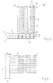
- FIG. 1 shows a conventional heat exchanger in a side view
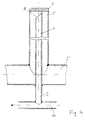
- FIG. 2 shows a heat exchanger according to the invention in a side view
- FIG. 3 is a top view of the heat exchanger of FIG. 2
- FIG. 4 is an enlarged illustration of a heat exchanger tube in an advantageous embodiment 5 shows a schematic side view of a fluidized bed dryer according to the invention.
- a manifold 1 for supplying hot steam as the heat transfer fluid is provided on the upper side thereof.
- Several straight distribution lines 2 extend laterally from the collecting line 1 and lead the hot steam into essentially vertical heat exchanger tubes 3.
- the upper part of the heat exchanger is located in the region of the fluidized bed W and is to be dried by means of an air flow from below (arrow direction) Well.
- the heat transfer fluid After the heat transfer fluid has given up its thermal energy to this material in the fluidized bed W and has essentially been completely condensed, the heat transfer fluid emerges from several pipes 3 lying next to one another as condensate into lower exhaust lines 4.
- Several exhaust lines 4 open into a lower area of the heat exchanger, common collection drain line 5.
- the manifold 1 'for supplying the heated heat transfer fluid is located in its lower region. Also from this manifold 1 'are laterally essentially horizontal distribution lines 2' which supply several vertically standing heat exchanger tubes 3 '. These tubes 3 ′ are free at their upper end 3 ′′ and, when used in a fluidized bed dryer, protrude into the fluidized bed W with this free end 3 ′′, preferably closed off by a flat plate 6.
- the heat exchanger tube 3 In the interior of the heat exchanger tube 3 'there is concentrically a second tube 7 with an outer diameter which is smaller than that of the heat exchanger tube 3'. After the heat transfer fluid has flowed up in the tube 3 'and thereby released its thermal energy to the material to be dried in the fluidized bed W, it also condenses in the space between the inner tube 7 and the inside of the heat exchanger tube 3'. The condensate gets back into the distribution line 2 'and the collecting line 1', both of which also act as condensate drains here. Hatching steam and / or air enters the inner tube 7 through at least one opening 8 and is guided downwards therein.
- inner tube 7 with an extension 9 passed through the distribution line 2 ' At the lower end of the heat exchanger tube 3 ' second, inner tube 7 with an extension 9 passed through the distribution line 2 '.
- all inner tubes 7 of the heat exchanger tubes 3 'connected to a distributor line 2' are also connected to a common lower derivative 10, which preferably leads below but parallel to the distributor line 2 'to a collecting derivative 11 for air and slip steam .
- This collecting line 11 also preferably runs below the collecting line 1 ', preferably parallel to it.
- a plurality of essentially straight, essentially horizontally lying and parallel distributor lines 2 ' are connected to a collecting line 1' - and also a collecting line 11 '.
- Each of these distribution lines 2 ' carries a plurality of vertical heat exchanger tubes 3', the upper ends of which protrude into the fluidized bed W.
- a single heat exchanger tube 3 'according to the invention is shown on a larger scale in Fig. 4.
- This pipe 3 ' is connected upright to the distribution line 2', welded to it in the simplest manner, and if necessary also attached removably.
- the inlet opening 8 for air or slip steam lies obliquely with respect to the axial direction, the inner tube 7 resting on the inside of the end plate 6 stabilizing the inner tube 7 in the heat transfer tube 3 '.
- the discharge line 10, 11 is of course larger in size and the distribution line 2 ', which now no longer has to serve to return condensate, can be made smaller.
- the inner, second tube 7 is extended through the distribution line 2 'and opens with this extension 9, which extends a little further downward beyond the underside of this line 2', into which the line 2 'is preferably parallel. running discharge line 10 for air or slip steam or cooled heat transfer fluid.
- a fluidized bed dryer with the heat exchanger WT according to the invention for drying the material fluidized in the fluidized bed W is shown schematically by way of example and in FIG.
- the air for fluidization is blown into the tower-shaped, preferably upwardly widening housing 12 of the dryer by means of a supply air fan 13. It passes the heat exchanger WT with its vertically standing heat exchanger tubes 3 ', to which superheated steam is supplied as heat transfer fluid via the manifold 1' and the condensate is removed. Slip vapor and air are discharged via line 10 and then 11.
Landscapes
- Engineering & Computer Science (AREA)
- Mechanical Engineering (AREA)
- General Engineering & Computer Science (AREA)
- Physics & Mathematics (AREA)
- Thermal Sciences (AREA)
- Life Sciences & Earth Sciences (AREA)
- Microbiology (AREA)
- Heat-Exchange Devices With Radiators And Conduit Assemblies (AREA)
Applications Claiming Priority (2)
| Application Number | Priority Date | Filing Date | Title |
|---|---|---|---|
| AT693/96 | 1996-04-17 | ||
| AT0069396A AT405685B (de) | 1996-04-17 | 1996-04-17 | Wärmetauscher |
Publications (2)
| Publication Number | Publication Date |
|---|---|
| EP0802384A2 true EP0802384A2 (fr) | 1997-10-22 |
| EP0802384A3 EP0802384A3 (fr) | 1999-03-10 |
Family
ID=3497337
Family Applications (1)
| Application Number | Title | Priority Date | Filing Date |
|---|---|---|---|
| EP97103857A Withdrawn EP0802384A3 (fr) | 1996-04-17 | 1997-03-07 | Echangeur de chaleur |
Country Status (3)
| Country | Link |
|---|---|
| US (1) | US5940987A (fr) |
| EP (1) | EP0802384A3 (fr) |
| AT (1) | AT405685B (fr) |
Cited By (2)
| Publication number | Priority date | Publication date | Assignee | Title |
|---|---|---|---|---|
| EP2505949A3 (fr) * | 2011-04-01 | 2014-07-30 | H S Beratung GmbH & Co. KG | Séchoir ainsi que procédé de séchage de matières de départ humides |
| WO2023104401A1 (fr) * | 2021-12-09 | 2023-06-15 | Andritz Technology And Asset Management Gmbh | Élément échangeur de chaleur et son utilisation |
Families Citing this family (7)
| Publication number | Priority date | Publication date | Assignee | Title |
|---|---|---|---|---|
| WO2003001334A2 (fr) * | 2001-06-22 | 2003-01-03 | Wonderware Corporation | Telesurveillance/telediagnostic centralises de composants repartis d'une application de commande de processus de controle et d'informations de fabrication |
| JP5050241B2 (ja) * | 2007-01-29 | 2012-10-17 | 株式会社Kelk | 流体温調装置 |
| RU2484403C2 (ru) * | 2010-03-29 | 2013-06-10 | Государственное образовательное учреждение высшего профессионального образования "Воронежский государственный технический университет" | Регенеративный теплообменник |
| RU2484404C2 (ru) * | 2010-03-29 | 2013-06-10 | Государственное образовательное учреждение высшего профессионального образования "Воронежский государственный технический университет" | Способ теплообмена газовых сред |
| DE102011014131A1 (de) * | 2011-03-15 | 2012-09-20 | Thyssenkrupp Uhde Gmbh | Verfahren zur Trocknung von feuchtem Polymerpulver und dafür geeignete Vorrichtung |
| US10094595B1 (en) * | 2012-05-10 | 2018-10-09 | Lockheed Martin Corporation | Solar heat collector |
| US11614287B2 (en) | 2021-06-24 | 2023-03-28 | Darby Renewable Energy Design Systems Inc. | Heat exchanger |
Family Cites Families (13)
| Publication number | Priority date | Publication date | Assignee | Title |
|---|---|---|---|---|
| DE231602C (fr) * | ||||
| GB1391430A (en) * | 1971-06-23 | 1975-04-23 | Ici Ltd | Tubular heat exchanger and use thereof in fluidised beds |
| GB1525222A (en) * | 1973-05-05 | 1978-09-20 | Pearce A | Fluidised beds |
| FR2308052A1 (fr) * | 1975-04-18 | 1976-11-12 | Commissariat Energie Atomique | Echangeur de chaleur a tubes plongeurs |
| US3982901A (en) * | 1975-06-25 | 1976-09-28 | Dorr-Oliver Incorporated | Heat transfer element and tuyere for fluidized bed reactor |
| US4290387A (en) * | 1979-10-04 | 1981-09-22 | Curtiss-Wright Corporation | Fluidized bed combustor and tube construction therefor |
| JPS5677692A (en) * | 1979-11-27 | 1981-06-26 | Toyo Eng Corp | Heat exchanger |
| US4452233A (en) * | 1982-03-04 | 1984-06-05 | Goodman Jr Maurice | Solar energy collector |
| AU558049B2 (en) * | 1982-10-08 | 1987-01-15 | Asea Stal Aktiebolag | Collection of spent material and fly ash from a pressurised fluidised bed combustor |
| US4882283A (en) * | 1987-11-17 | 1989-11-21 | Phillips Petroleum Company | Heat exchange apparatus |
| SE464781B (sv) * | 1989-06-21 | 1991-06-10 | Nonox Eng Ab | Anordning foer indirekt uppvaermning av luft med hoegt tryck till hoeg temperatur samt anvaendning av anordningen |
| DE4008903A1 (de) * | 1990-03-20 | 1991-09-26 | Kloeckner Humboldt Deutz Ag | Verfahren und vorrichtung zum trocknen von feuchten materialien in einer wirbelschicht |
| US5353864A (en) * | 1993-03-01 | 1994-10-11 | Fmc Corporation | Mass flow cooler |
-
1996
- 1996-04-17 AT AT0069396A patent/AT405685B/de not_active IP Right Cessation
-
1997
- 1997-03-07 EP EP97103857A patent/EP0802384A3/fr not_active Withdrawn
- 1997-04-14 US US08/843,303 patent/US5940987A/en not_active Expired - Fee Related
Cited By (2)
| Publication number | Priority date | Publication date | Assignee | Title |
|---|---|---|---|---|
| EP2505949A3 (fr) * | 2011-04-01 | 2014-07-30 | H S Beratung GmbH & Co. KG | Séchoir ainsi que procédé de séchage de matières de départ humides |
| WO2023104401A1 (fr) * | 2021-12-09 | 2023-06-15 | Andritz Technology And Asset Management Gmbh | Élément échangeur de chaleur et son utilisation |
Also Published As
| Publication number | Publication date |
|---|---|
| ATA69396A (de) | 1999-02-15 |
| US5940987A (en) | 1999-08-24 |
| EP0802384A3 (fr) | 1999-03-10 |
| AT405685B (de) | 1999-10-25 |
Similar Documents
| Publication | Publication Date | Title |
|---|---|---|
| DE3507981A1 (de) | Waermetauscher mit getrennt angeordneten verdampfungs-und kondensationszonen | |
| DE19648128C2 (de) | Rost für eine Feuerungsanlage | |
| EP0943435B1 (fr) | Cylindre réfrigérant | |
| EP0768424A2 (fr) | Cylindre chauffant | |
| CH640631A5 (de) | Waermeaustauscher. | |
| AT405685B (de) | Wärmetauscher | |
| DE1942157A1 (de) | Luftgekuehlter Kondensator | |
| DE1958885B2 (de) | Einrichtung zum trocknen und ueberhitzen von nassdampf in dampfkraftanlagen | |
| EP0157920B1 (fr) | Rouleau de grille pour grille à rouleaux par exemple d'une installation d'incinération des ordures ou similaire | |
| DE2405999B2 (de) | Naturzug-trockenkuehlturm | |
| DE19518323A1 (de) | Verfahren und Vorrichtung zum unterbrechungsfreien Wärmetausch | |
| EP0123986A1 (fr) | Réchauffeur d'eau d'alimentation | |
| DE2522070A1 (de) | Walzgutfuehrung fuer ein walzgeruest | |
| DE2524080C3 (de) | Wärmeübertrager, in dem ein dampfförmiges Medium unter Wärmeabgabe an ein anderes Medium kondensiert | |
| DE3016981C2 (fr) | ||
| DE2712794C2 (de) | Dampfüberhitzer horizontaler Achse für die Beaufschlagung einer Hochleistungsturbine | |
| DE20010671U1 (de) | Wärmetauscher für rieselfähige Feststoffe | |
| CH662638A5 (de) | Waermeuebertragersystem, vorzugsweise fuer ein prozessgas. | |
| EP1191282A1 (fr) | Barreau de grille refroidi | |
| EP0097989B1 (fr) | Réchauffeur d'eau d'alimentation à haute pression disposé verticalement à construction à collecteur avec un désurchauffeur et un séparateur eau-vapeur | |
| EP3596390B1 (fr) | Barreau de grille, grille et installation de combustion | |
| DE102006053812B4 (de) | Rohrabstützung mit integrierter Reinigungseinrichtung | |
| DE1078146B (de) | Waermetauscher mit in einer Reihe nebeneinander angeordneten und ueber einen gemeinsamen mit Leitvorrichtungen versehenen Verteiler- bzw. Sammelkanal verbundenen Elementen | |
| DE3908277A1 (de) | Erosionsschutz fuer waermetauscher | |
| DE3148132C2 (de) | Wärmetauscher, insbesondere stehender Speisewasservorwärmer mit Dampfnässeabscheider |
Legal Events
| Date | Code | Title | Description |
|---|---|---|---|
| PUAI | Public reference made under article 153(3) epc to a published international application that has entered the european phase |
Free format text: ORIGINAL CODE: 0009012 |
|
| AK | Designated contracting states |
Kind code of ref document: A2 Designated state(s): DE ES FR GB IT |
|
| PUAL | Search report despatched |
Free format text: ORIGINAL CODE: 0009013 |
|
| AK | Designated contracting states |
Kind code of ref document: A3 Designated state(s): DE ES FR GB IT |
|
| 17P | Request for examination filed |
Effective date: 19990719 |
|
| RAP1 | Party data changed (applicant data changed or rights of an application transferred) |
Owner name: ANDRITZ AG |
|
| STAA | Information on the status of an ep patent application or granted ep patent |
Free format text: STATUS: THE APPLICATION IS DEEMED TO BE WITHDRAWN |
|
| 18D | Application deemed to be withdrawn |
Effective date: 20011002 |