EP0802311B1 - Kraftstoffregelventil - Google Patents
Kraftstoffregelventil Download PDFInfo
- Publication number
- EP0802311B1 EP0802311B1 EP97302246A EP97302246A EP0802311B1 EP 0802311 B1 EP0802311 B1 EP 0802311B1 EP 97302246 A EP97302246 A EP 97302246A EP 97302246 A EP97302246 A EP 97302246A EP 0802311 B1 EP0802311 B1 EP 0802311B1
- Authority
- EP
- European Patent Office
- Prior art keywords
- valve
- sleeve
- exit
- valve block
- inlet
- Prior art date
- Legal status (The legal status is an assumption and is not a legal conclusion. Google has not performed a legal analysis and makes no representation as to the accuracy of the status listed.)
- Expired - Lifetime
Links
- 239000000446 fuel Substances 0.000 title claims description 52
- 239000012530 fluid Substances 0.000 claims description 26
- 238000006073 displacement reaction Methods 0.000 description 8
- 230000003628 erosive effect Effects 0.000 description 8
- 230000001627 detrimental effect Effects 0.000 description 2
- 239000000463 material Substances 0.000 description 2
- 230000007423 decrease Effects 0.000 description 1
- 230000003247 decreasing effect Effects 0.000 description 1
- 238000007599 discharging Methods 0.000 description 1
- 230000000694 effects Effects 0.000 description 1
- 230000003287 optical effect Effects 0.000 description 1
- 238000011144 upstream manufacturing Methods 0.000 description 1
Images

Classifications
-
- F—MECHANICAL ENGINEERING; LIGHTING; HEATING; WEAPONS; BLASTING
- F02—COMBUSTION ENGINES; HOT-GAS OR COMBUSTION-PRODUCT ENGINE PLANTS
- F02C—GAS-TURBINE PLANTS; AIR INTAKES FOR JET-PROPULSION PLANTS; CONTROLLING FUEL SUPPLY IN AIR-BREATHING JET-PROPULSION PLANTS
- F02C7/00—Features, components parts, details or accessories, not provided for in, or of interest apart form groups F02C1/00 - F02C6/00; Air intakes for jet-propulsion plants
- F02C7/22—Fuel supply systems
- F02C7/232—Fuel valves; Draining valves or systems
-
- F—MECHANICAL ENGINEERING; LIGHTING; HEATING; WEAPONS; BLASTING
- F02—COMBUSTION ENGINES; HOT-GAS OR COMBUSTION-PRODUCT ENGINE PLANTS
- F02C—GAS-TURBINE PLANTS; AIR INTAKES FOR JET-PROPULSION PLANTS; CONTROLLING FUEL SUPPLY IN AIR-BREATHING JET-PROPULSION PLANTS
- F02C9/00—Controlling gas-turbine plants; Controlling fuel supply in air- breathing jet-propulsion plants
- F02C9/26—Control of fuel supply
- F02C9/263—Control of fuel supply by means of fuel metering valves
-
- F—MECHANICAL ENGINEERING; LIGHTING; HEATING; WEAPONS; BLASTING
- F16—ENGINEERING ELEMENTS AND UNITS; GENERAL MEASURES FOR PRODUCING AND MAINTAINING EFFECTIVE FUNCTIONING OF MACHINES OR INSTALLATIONS; THERMAL INSULATION IN GENERAL
- F16K—VALVES; TAPS; COCKS; ACTUATING-FLOATS; DEVICES FOR VENTING OR AERATING
- F16K3/00—Gate valves or sliding valves, i.e. cut-off apparatus with closing members having a sliding movement along the seat for opening and closing
- F16K3/22—Gate valves or sliding valves, i.e. cut-off apparatus with closing members having a sliding movement along the seat for opening and closing with sealing faces shaped as surfaces of solids of revolution
- F16K3/24—Gate valves or sliding valves, i.e. cut-off apparatus with closing members having a sliding movement along the seat for opening and closing with sealing faces shaped as surfaces of solids of revolution with cylindrical valve members
- F16K3/26—Gate valves or sliding valves, i.e. cut-off apparatus with closing members having a sliding movement along the seat for opening and closing with sealing faces shaped as surfaces of solids of revolution with cylindrical valve members with fluid passages in the valve member
-
- F—MECHANICAL ENGINEERING; LIGHTING; HEATING; WEAPONS; BLASTING
- F16—ENGINEERING ELEMENTS AND UNITS; GENERAL MEASURES FOR PRODUCING AND MAINTAINING EFFECTIVE FUNCTIONING OF MACHINES OR INSTALLATIONS; THERMAL INSULATION IN GENERAL
- F16K—VALVES; TAPS; COCKS; ACTUATING-FLOATS; DEVICES FOR VENTING OR AERATING
- F16K31/00—Actuating devices; Operating means; Releasing devices
- F16K31/02—Actuating devices; Operating means; Releasing devices electric; magnetic
- F16K31/06—Actuating devices; Operating means; Releasing devices electric; magnetic using a magnet, e.g. diaphragm valves, cutting off by means of a liquid
-
- Y—GENERAL TAGGING OF NEW TECHNOLOGICAL DEVELOPMENTS; GENERAL TAGGING OF CROSS-SECTIONAL TECHNOLOGIES SPANNING OVER SEVERAL SECTIONS OF THE IPC; TECHNICAL SUBJECTS COVERED BY FORMER USPC CROSS-REFERENCE ART COLLECTIONS [XRACs] AND DIGESTS
- Y10—TECHNICAL SUBJECTS COVERED BY FORMER USPC
- Y10T—TECHNICAL SUBJECTS COVERED BY FORMER US CLASSIFICATION
- Y10T137/00—Fluid handling
- Y10T137/8158—With indicator, register, recorder, alarm or inspection means
- Y10T137/8326—Fluid pressure responsive indicator, recorder or alarm
Definitions
- This invention applies to gas turbine engine fuel controls in general, and to gas turbine engine fuel flow control valves in particular.
- Fuel control valves for high performance gas turbine powered aircraft must perform with a high degree of accuracy under a wide variety of operating conditions. A valve that meters too little or too much fuel to the combustor could cause a combustor to "blowout", or could hinder reignition within the combustor. To avoid such problems, valve design considers the difference in pressure across the fuel control valve and the mass flow rate of fluid through the valve. These two parameters are generally used to define the required performance of the fuel control valve within the aircraft flight envelope.
- the difference in pressure ( ⁇ p ) "across" the valve is by consensus defined to be the difference between the pressure of the fuel discharging from the fuel pump less component and piping head losses between the pump discharge and the control valve ( P FPD ) and the pressure of the fuel dispensed within the combustor(s) less component and piping head losses between the control valve and the combustor ( P FC ).
- the mass flow rate of the fluid passing through the valve may be determined by the equation: W f - KC d A v ⁇ p ⁇
- W f represents the mass flow rate of the fluid
- K represents a conversion factor constant
- C d represents a discharge coefficient for flow exiting the valve orifice
- a v represents the cross-sectional area of the valve orifice
- ⁇ represents the density of the fluid.
- the discharge coefficient ( C d ) is a coefficient that compensates for less than frictionless/ideal flow through an orifice and is a function of: (1) the geometry of the orifice relative to upstream passage geometry; and (2) the Reynolds number of the fluid passing through the orifice.
- the Reynolds number of the fluid passing through the orifice accounts for the velocity of the fluid within the orifice, the dimensions of the orifice, and the kinematic viscosity of the fluid.
- the discharge coefficient ( C d ) may be considered a constant for a particular point within the flight envelope. This is in part due to a relatively low fluid velocity through the orifice.
- the mass flow rate of fluid ( W f ) and therefore the power setting of the engine, can be readily controlled by changing only the cross-sectional area of the valve orifice ( A v ).
- head regulator which is a device designed to maintain a particular ⁇ p across a fuel control valve under all conditions.
- head regulators do provide the advantage of a constant ⁇ p across the fuel flow control valve, they also provide several distinct disadvantages.
- head regulators used in high pressure applications tend to be of considerable size and weight, neither of which is desirable.
- Head regulators also add a second layer of complexity to the fuel control system; e.g. they require sensor input to operate and a flow valve to regulate a constant head across a metering valve.
- the sensors and the valves within the head regulator provide additional potential failure modes which are difficult, if not impossible, to diagnose. Head regulators also add significantly to the cost of most gas turbine fuel flow control systems.
- the advantage of a constant ⁇ p across the control valve is offset by several distinct disadvantages.
- US 4876857 shows an example of a fuel control valve having inlet and exit ports that are operated independently.
- valve for controlling the flow of fuel as claimed in claim 1.
- the sleeve of the fuel flow control valve is disposed within a component housing.
- the housing includes a fluid inlet means and exit means aligned with the inlet port and exit port of the valve sleeve, respectively.
- An advantage of the present invention is that a more accurate fuel flow control valve is provided for a gas turbine engine.
- the present fuel flow control valve allows the pressure drop across the entire valve to be split into two discrete pressure drops, and thereby decreases fluid velocity passing through either orifice. Decreasing the fluid velocity through the orifices minimizes cavitation and the C d instability associated therewith.
- Splitting the pressure drop across the valve into two discrete drops also helps prevent detrimental erosion. Cavitation can cause erosion of hardware adjacent the cavitation path and the significance of the erosion generally increases with the level of cavitation.
- the present invention helps minimize erosion by first minimizing cavitation.
- the present invention also minimizes the detrimental effects of erosion by varying the amount of ⁇ p that occurs across the inlet port versus the exit port. Providing an inlet port geometry that causes a higher percentage of the ⁇ p to occur across the inlet port than the exit port will cause most or all of any cavitation that does occur to do so within the fuel flow control valve where erosion resistant materials may be utilized.
- Another advantage of the present invention is that it provides an improvement in leakage performance through the valve.
- Prior art fuel control valves having a single port with a large pressure drop across the port are often subject to significant leakage because of: (1) the significant pressure difference across the port driving the fluid; and (2) pressure induced mechanical distortion which provides leak paths for the fluid.
- the leakage negatively affects the performance of the valve by altering the intended flow rate.
- the present invention splits the pressure drop across the entire valve into two discrete zones. The smaller pressure drop across each port results in less leakage because: (1) the pressure difference driving the fluid is less; and (2) mechanical distortion within the valve is less.
- Still another advantage of the present invention is that fuel flow through the valve is readily controlled.
- the preferred embodiment provides a pair of variable orifices which are manipulated by displacing one of the valve block or the sleeve relative to the other. Both orifices may therefore be controlled by a single actuation device sensed by a single position control device.
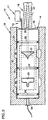
- a fuel flow control valve 10 for a gas turbine engine (not shown) includes a valve block 12 disposed within a sleeve 14, means 16 for displacing one of the sleeve 14 or valve block 12 relative to the other, and means 17 for sensing the displacement of the sleeve 14 or valve block 12 relative to the other.
- the sleeve 14 is disposed within a component housing 18 attached to the periphery of a gas turbine engine.
- the sleeve 14 is cylindrically shaped and includes a pair of inlet ports 20, a pair of exit ports 22, and an internal cavity 24. Each inlet port 20 is diametrically opposite the other inlet port 20.
- Each exit port 22 is diametrically opposite the other exit port 22.
- "O"-rings 26 positioned within grooves 28 disposed within the outer surface 30 of the sleeve 14 seal between the component housing 18 and the sleeve 14.
- the valve block 12 includes a pair of inlet gates 32 and a pair of exit gates 34.
- the gates 32,34 are separated a distance sufficient to enable communication with the inlet 20 and exit 22 ports when the valve block 12 is disposed within the sleeve 14.
- the geometries of the ports 20,22 (see FIG.3) and gates 32,34 are chosen to provide flow characteristics for whatever application is at hand. Specifically, different geometries can provide different flow rate of changes as the valve block 12 and sleeve 14 are displaced relative to one another; e.g., a step function change, or an exponential change, or a linear change in flow rate. In the embodiments shown in FIGS.
- valve block 12 is cylindrically shaped and includes openings 36 disposed between the inlet 32 and exit 34 gates. "O"-rings 38 positioned within grooves 40 disposed within the outer surface 42 of the valve block 12 seal between the sleeve 14 and the valve block 12.
- the component housing 18 includes an inlet channel 44 and an exit 46 channel disposed within a bore 48 for receiving the sleeve 14.
- the channels 44,46 are connected by passage means 50,52 which enable fuel to enter the inlet channel 44 and pass out of the exit channel 46.
- each channel 44,46 forms an annulus around the periphery of the sleeve 14.
- the aforementioned "O"-rings 26 disposed within the outer surface 30 of the sleeve 14 seal between the component housing 18 and the sleeve 14.
- the means 16 for displacing one of the sleeve 14 or valve block 12 relative to the other is shown as an electromechanical solenoid 54 type device.
- the plunger 56 of the solenoid 54 is attached to the valve block 12 and can be actuated to displace the valve block 12 relative to the valve sleeve 14.
- the solenoid 54 can be attached to the sleeve 14 for displacing the sleeve 14 relative to the valve block 12.
- Other linear actuators including a hydraulic actuator coupled with a hydraulic servo valve (not shown) may be used alternatively. Linear displacement of one of the sleeve 14 or valve block 12 relative to the other may be described as axial displacement.
- the means 17 for sensing displacement of the sleeve 14 or valve block 12 relative to the other is a linear variable displacement transducer (LVDT) 19, shown diagrammatically in FIGS. 1-3.
- LVDT linear variable displacement transducer
- a person of skill in the art will recognize that a variety of LVDT's 19 are available for sensing linear displacement including magnetic, optical, and electrical devices. In all cases, the output of the LVDT 19 is calibrated to indicate the position of the valve block 12 and the sleeve 14 relative to one another.
- the valve 10 may start at a closed position as is shown in FIG. 1.
- the inlet 32 and exit 34 gates align with the inlet 20 and exit 22 ports, respectively, thereby preventing fluid flow through the ports 20,22 into the cavity 24 of the sleeve 14.
- the "o"-rings 26 disposed between the outer surface 30 of the sleeve 14 and the component housing 18 prevent fuel from entering the cavity 24 of the sleeve 14 or the component housing 18 via whatever leakage path exists, if any, between the sleeve 14 and the housing 18.
- the inlet gates 32 do not impede the flow of fuel 57 (see FIG.2) entering the cavity 24 of the sleeve 14 via the inlet port 20.
- the exit gates 34 do not impede the flow of fuel 58 exiting the cavity 24 via the openings 36 and the exit ports 22.
- Less than maximum fuel flow rate may be accomplished by displacing the valve block 12 relative to the sleeve 14 (or vice versa) such that a portion of the gates 20,22 align with the ports 32,34, thereby impeding the passage of flow therethrough.
- the inlet and outlet ports 20,22 are first and second variable orifices.
- a reference signal value stored in a controller (not shown) is associated with a particular valve position and magnitude of fuel flow. The valve block 12 is displaced until the LVDT 19 signal compares favourably with the reference signal value.
- Fuel entering the cavity 24 via the inlet ports 20 is motivated by a difference in pressure between the fuel exiting the fuel pump (not shown) and the fuel within the internal cavity 24 of the sleeve 14.
- a pressure sensor 58 in communication with the cavity 24 is used to determine pressure within the cavity 24.
- Fuel exiting the cavity 24 via the exit port 22 is motivated by a difference in pressure between the fuel within the cavity 24 and the fuel within the gas turbine engine combustor(s) (not shown).
- the inlet 20 or exit 22 ports may be established to perform as a throttling orifice and the other as a metering orifice. If the inlet port 20 acts as a throttle and the exit port 22 as a meter, then the pressure difference between the internal cavity 24 and the combustor(s) (not shown) may be used to calculate the fuel flow rate through the entire valve 10. Measuring the fuel flow rate across only one of the inlet 20 or exit 22 ports eliminates whatever inaccuracies may be associated with including the additional orifice; e.g., port cross-sectional area inaccuracies, pressure difference inaccuracies, etc.
- valve 10 may be configured and operated such that the pressure drop across the inlet port 20 is larger than that across the exit port 22. This causes cavitation in the fuel supply system to occur substantially within the valve 10, where erosion resistant materials may be used.
- valve block 12 or sleeve 14 may be rotated relative to the other to open and close the ports 20,22 of the valve 10.
- Rotary displacement of one of the sleeve 14 or valve block 12 relative to the other may be described as radial displacement.
- both the sleeve 14 and the valve block 12 have been described as being cylindrically shaped.
- one or both of the sleeve 14 and valve block 12 may assume noncylindrical shapes.
- the present invention provides a fuel control valve that accurately meters fuel flow, that accommodates large differences in pressure across the valve, that is readily controlled and that minimizes erosion attributable to cavitation.
Landscapes
- Engineering & Computer Science (AREA)
- Chemical & Material Sciences (AREA)
- Combustion & Propulsion (AREA)
- General Engineering & Computer Science (AREA)
- Mechanical Engineering (AREA)
- Lift Valve (AREA)
- Sliding Valves (AREA)
- Magnetically Actuated Valves (AREA)
- Flow Control (AREA)
- Fuel-Injection Apparatus (AREA)
Claims (11)
- Ventil (10) zum Steuern der Brennstoffströmung in einer Gasturbinenmaschine, aufweisend:wobei entweder die Hülse (14) oder der Ventilblock (12) relativ zu dem Ventilblock (12) bzw. der Hülse (14) verschoben werden kann aus einer geschlossenen Position, bei der die Sperren (32; 34) die Öffnungen (20, 22) schließen und so Fluidströmung durch das Ventil (10) durch die Öffnungen (20, 22) verhindern;eine Hülse (14) mit einer Einlassöffnung (20) und einer Auslassöffnung (22), welche in der Wand der Hülse (14) angeordnet sind; undeinen Ventilblock (12) mit eine Einlasssperre (32) und einer Auslasssperre (34);
dadurch gekennzeichnet, dass die Einlassöffnung (20) in der Wand der Hülse (14) angeordnet ist; und
dass entweder die Hülse (14) oder der Ventilblock (12) relativ zu dem Ventilblock (12) bzw. der Hülse (14) aus der geschlossenen Position zu einer Mehrzahl von offenen Positionen verlagert werden kann, in jeder von denen die Sperren (32, 34) die Öffnungen (20, 22) weniger als vollständig schließen und so eine Fluidströmung durch das Ventil (10) über die Öffnungen (20, 22) ermöglichen. - Ventil nach Anspruch 1, wobei die Hülse (14) ferner aufweist:wobei Fluid, welches in einer der offenen Positionen in das Ventil eintritt, in das Ventil (10) über die Einlassöffnung (20) eintritt und in den internen Hohlraum (24) strömt; undeinen internen Hohlraum (24) in Kommunikation mit den Einlass- und Auslassöffnungen (20, 22);
wobei Fluid, welches das Ventil(10) in einer der offenen Positionen verlässt, aus dem internen Hohlraum (24) strömt und das Ventil über die Auslassöffnung (22) verlässt. - Ventil nach Anspruch 2, ferner aufweisend:eine Einrichtung (58) zum Messen von Fluiddruck in dem internen Hohlraum (24).
- Ventil nach einem der vorangehenden Ansprüche, wobei die Hülse (14) im wesentlichen zylindrisch geformt ist und der Ventilblock (12) verschiebbar in der Hülse (14) aufgenommen ist.
- Ventil nach einem der vorangehenden Ansprüche, wobei entweder die Hülse (14) oder der Ventilblock (12) relativ zu dem Ventilblock (12) bzw. der Hülse (14) axial verschoben werden kann.
- Ventil nach einem der vorangehenden Ansprüche, wobei der Ventilblock (12) zylindrisch geformt ist.
- Ventil nach einem der vorangehenden Ansprüche, ferner aufweisend:eine Einrichtung (16) zum Verlagern entweder der Hülse (14) oder des Ventilblocks (12) relativ zu dem Ventilblock (12) bzw. der Hülse (14) zwischen der geschlossenen Position und der Mehrzahl von offenen Positionen.
- Ventil nach einem der vorangehenden Ansprüche, ferner aufweisend:wobei die Hülse (14) und die Einlass- und Auslasskanäle (44, 46) jeweils einen Einlassring und einen Auslassring bilden, wenn die Hülse (14) in der Bohrung (48) aufgenommen ist.ein Gehäuse (18) mit einem Einlasskanal (44) und einem Auslasskanal (46), welche in einer Bohrung (48) in dem Gehäuse angeordnet sind, wobei die Kanäle (44, 46) Durchgangseinrichtungen (50, 52) aufweisen, durch welche Fluid in den Einlasskanal (44) und aus dem Auslasskanal (46) heraus strömen kann;
- Ventil nach einem der vorangehenden Ansprüche, ferner aufweisend:eine Einrichtung (17) zum Erfassen der Position entweder der Hülse (14) oder des Ventilblocks (12) relativ zu dem Ventilblock (12) bzw. der Hülse (14).
- Ventil nach einem der vorangehenden Ansprüche:
wobei die Einlassöffnung (20) und die Einlasssperre (32) einen ersten, variablen Durchlass (20) bilden;
wobei die Auslassöffnung (22) und die Auslasssperre (34) einen zweiten variablen Durchlass (22) bilden; ferner aufweisend:wobei die Durchlässe zusammen durch die Einrichtung zum Betätigen betätigt werden können von einer geschlossenen Position, in der die Durchlässe eine Fluidströmung durch das Ventil verhindern, zu einer Mehrzahl von offenen Positionen, in denen die Durchlässe eine Fluidströmung durch das Ventil weniger als vollständig verhindern.eine Einrichtung (16) zum Betätigen der variablen Durchlässe im Gleichlauf; undeine Einrichtung (17) zum Erfassen der Position der variablen Durchlässe; - Brennstoffversorgungssystem für eine Gasturbinenmaschine, welches ein Ventil (10) gemäß einem der vorangehenden Ansprüche aufweist.
Applications Claiming Priority (2)
| Application Number | Priority Date | Filing Date | Title |
|---|---|---|---|
| US08/635,224 US5772182A (en) | 1996-04-17 | 1996-04-17 | Fuel flow control valve |
| US635224 | 1996-04-17 |
Publications (3)
| Publication Number | Publication Date |
|---|---|
| EP0802311A2 EP0802311A2 (de) | 1997-10-22 |
| EP0802311A3 EP0802311A3 (de) | 1999-10-13 |
| EP0802311B1 true EP0802311B1 (de) | 2004-07-28 |
Family
ID=24546960
Family Applications (1)
| Application Number | Title | Priority Date | Filing Date |
|---|---|---|---|
| EP97302246A Expired - Lifetime EP0802311B1 (de) | 1996-04-17 | 1997-04-02 | Kraftstoffregelventil |
Country Status (5)
| Country | Link |
|---|---|
| US (2) | US5772182A (de) |
| EP (1) | EP0802311B1 (de) |
| JP (1) | JP4009881B2 (de) |
| KR (1) | KR970070471A (de) |
| DE (1) | DE69729971T2 (de) |
Families Citing this family (41)
| Publication number | Priority date | Publication date | Assignee | Title |
|---|---|---|---|---|
| US6194057B1 (en) | 1998-11-12 | 2001-02-27 | Paper Technology Foundation Inc. | Partially impregnated lignocellulosic materials |
| US6537616B2 (en) | 1998-11-12 | 2003-03-25 | Paper Technology Foundation Inc. | Stam-assisted paper impregnation |
| US6537615B2 (en) | 1998-11-12 | 2003-03-25 | Paper Technology Foundation Inc. | Steam-assisted paper impregnation |
| US6687936B2 (en) | 2001-01-18 | 2004-02-10 | Roho, Inc. | Valve for zoned cellular cushion |
| EP1352189B1 (de) * | 2001-01-18 | 2008-06-04 | Roho, Inc. | Ventil für in zonen eingeteiltes zellenförmiges kissen |
| US7108493B2 (en) * | 2002-03-27 | 2006-09-19 | Argo-Tech Corporation | Variable displacement pump having rotating cam ring |
| FR2825120B1 (fr) * | 2001-05-25 | 2003-12-12 | Snecma Moteurs | Doseur a 2 sorties integrees |
| JP2003206755A (ja) * | 2002-01-10 | 2003-07-25 | Ebara Corp | ガスタービン装置 |
| GB0305566D0 (en) * | 2003-03-11 | 2003-04-16 | Microgen Energy Ltd | A splitter valve |
| US20060174954A1 (en) * | 2003-03-28 | 2006-08-10 | Hasko Stephen M | Splitter valve |
| US20040216782A1 (en) | 2003-05-03 | 2004-11-04 | Mares E. Joseph | Gas turbine metering valve |
| GB0421634D0 (en) * | 2004-09-29 | 2004-10-27 | Microgen Energy Ltd | A splitter valve |
| US7401751B2 (en) * | 2005-05-24 | 2008-07-22 | Eaton Corporation | Fluid flow regulator with overpressure relief function |
| US7481061B2 (en) * | 2005-11-10 | 2009-01-27 | Siemens Energy, Inc. | Fuel control for starting a gas turbine engine |
| EP1979593B1 (de) * | 2006-02-03 | 2017-12-06 | Rolls-Royce Corporation | Gasturbinenantriebsstoffsystem mit treibstoffmessendem ventil |
| US7565793B2 (en) * | 2006-02-27 | 2009-07-28 | Honeywell International Inc. | Gas turbine engine fuel control system having start / back up check valve (SBUC) providing a main fuel check valve function |
| GB0624945D0 (en) * | 2006-12-14 | 2007-01-24 | Microgen Energy Ltd | A heating system |
| US8047825B2 (en) * | 2007-04-09 | 2011-11-01 | United Technologies Corporation | Fluoropolymer-containing films for use with positive-displacement fluid pumps |
| US8312893B2 (en) * | 2008-05-02 | 2012-11-20 | Control Components, Inc. | Axial drag valve with internal hub actuator |
| US8235070B2 (en) * | 2008-06-02 | 2012-08-07 | Eaton Corporation | Two position three way valve |
| JP2010256174A (ja) * | 2009-04-24 | 2010-11-11 | Hitachi Ltd | ガスタービン制御装置 |
| FR2945075B1 (fr) * | 2009-04-29 | 2015-06-05 | Snecma | Procede et dispositif pour alimenter une chambre de turbomachine avec un debit de carburant regule |
| US8393156B2 (en) * | 2009-11-09 | 2013-03-12 | Woodward, Inc. | Variable performance valve of a fuel nozzle for a turbine engine |
| US8439073B2 (en) | 2010-09-10 | 2013-05-14 | Hamilton Sundstrand Corporation | Gate valve |
| US8800594B2 (en) * | 2012-02-02 | 2014-08-12 | Honeywell International Inc. | Gas turbine engine fuel return valve and system |
| US9989026B2 (en) | 2012-02-17 | 2018-06-05 | Ford Global Technologies, Llc | Fuel pump with quiet rotating suction valve |
| US9303607B2 (en) | 2012-02-17 | 2016-04-05 | Ford Global Technologies, Llc | Fuel pump with quiet cam operated suction valve |
| DE102014008651A1 (de) * | 2014-06-13 | 2015-12-17 | Rsg Electronic Gmbh | Ventilvorrichtung zum Ansteuern von Medienströmen jedweder Art |
| US9341270B2 (en) | 2014-07-28 | 2016-05-17 | Schneider Electric Buildings, Llc | Tool-less valve actuator connector for a globe valve assembly |
| US9541212B2 (en) | 2014-08-19 | 2017-01-10 | Schneider Electric Buildings, Llc | Tool-less valve stem connector assembly for a globe valve assembly |
| US9371936B2 (en) * | 2014-09-17 | 2016-06-21 | Schneider Electric Buildings, Llc | Balanced globe valve assembly |
| US9777644B2 (en) * | 2015-08-13 | 2017-10-03 | Snecma | Fuel meter protected from icing |
| EP3325787B1 (de) * | 2015-07-21 | 2022-05-11 | Safran Aircraft Engines | Gegen vereisung geschützte kraftstoffmessvorrichtung |
| US10309312B2 (en) | 2015-07-21 | 2019-06-04 | Safran Aircraft Engines | Fuel metering device protected against icing |
| FR3039210B1 (fr) * | 2015-07-21 | 2021-09-10 | Snecma | Doseur de carburant protege du givrage |
| US10557252B2 (en) * | 2016-11-28 | 2020-02-11 | 9309-0983 Québec Inc. | Fire hydrant valve and method for controlling a water flow in a fire hydrant conduit |
| WO2019220153A2 (en) | 2018-05-14 | 2019-11-21 | Hydromat D.O.O. | Axial valve of the modular concept of construction |
| FR3094042B1 (fr) * | 2019-03-20 | 2021-04-30 | Safran Aircraft Engines | Clapet de répartition de carburant pour injecteur de carburant et procédé de fonctionnement d’un tel clapet de répartition |
| US11378018B2 (en) * | 2020-06-11 | 2022-07-05 | Honeywell International Inc. | Fuel metering system |
| US11703134B2 (en) | 2021-08-20 | 2023-07-18 | Hamilton Sundstrand Corporation | Metering valve with mid-stroke shutoff |
| KR102799721B1 (ko) | 2021-12-29 | 2025-04-25 | 주식회사 스탠드업테라퓨티스 | 체세포로부터 운동성 신경세포로의 직접교차 분화를 위한 조성물 및 이의 용도 |
Family Cites Families (8)
| Publication number | Priority date | Publication date | Assignee | Title |
|---|---|---|---|---|
| US574500A (en) * | 1897-01-05 | Device for charging liquids with gas | ||
| US2941602A (en) * | 1955-05-02 | 1960-06-21 | United Aircraft Corp | Fuel control for turboprop engine |
| US3002350A (en) * | 1956-11-05 | 1961-10-03 | Bendix Corp | Fuel control device for combustion engines having means for avoiding compressor stall |
| GB2125110A (en) * | 1982-08-11 | 1984-02-29 | United Technologies Corp | Gas turbine augmentor fuel control system |
| US4760662A (en) * | 1987-04-24 | 1988-08-02 | United Technologies Corporation | Hybrid fuel metering system |
| US4876857A (en) * | 1988-08-15 | 1989-10-31 | Allied-Signal Inc. | Shut off/pressure regulating valve for turbine engine |
| US5111653A (en) * | 1990-04-11 | 1992-05-12 | Woodward Governor Company | Fuel delivery system with capacity monitor |
| GB9203770D0 (en) * | 1992-02-21 | 1992-04-08 | Lucas Ind Plc | Fuel control system |
-
1996
- 1996-04-17 US US08/635,224 patent/US5772182A/en not_active Expired - Lifetime
-
1997
- 1997-04-02 EP EP97302246A patent/EP0802311B1/de not_active Expired - Lifetime
- 1997-04-02 DE DE69729971T patent/DE69729971T2/de not_active Expired - Lifetime
- 1997-04-16 KR KR1019970013917A patent/KR970070471A/ko not_active Ceased
- 1997-04-16 JP JP11358897A patent/JP4009881B2/ja not_active Expired - Fee Related
- 1997-09-10 US US08/927,679 patent/US5983621A/en not_active Expired - Lifetime
Also Published As
| Publication number | Publication date |
|---|---|
| KR970070471A (ko) | 1997-11-07 |
| US5983621A (en) | 1999-11-16 |
| EP0802311A2 (de) | 1997-10-22 |
| EP0802311A3 (de) | 1999-10-13 |
| JPH1047084A (ja) | 1998-02-17 |
| DE69729971T2 (de) | 2004-12-16 |
| DE69729971D1 (de) | 2004-09-02 |
| US5772182A (en) | 1998-06-30 |
| JP4009881B2 (ja) | 2007-11-21 |
Similar Documents
| Publication | Publication Date | Title |
|---|---|---|
| EP0802311B1 (de) | Kraftstoffregelventil | |
| US8393344B2 (en) | Microvalve device with pilot operated spool valve and pilot microvalve | |
| CA1123709A (en) | Differential area electrohydraulic doser actuator | |
| US5442922A (en) | Fuel staging system | |
| EP0105017B1 (de) | Durchflussregler | |
| US6981359B2 (en) | Centrifugal pump fuel system and method for gas turbine engine | |
| US8794262B2 (en) | Quantum fluid transfer system | |
| US4986305A (en) | Fluidic multiplexer | |
| US9212608B2 (en) | Low friction fuel metering valve | |
| US10203704B2 (en) | Fluid metering valve | |
| US6092546A (en) | Fuel flow divider and pressurizing valve for gas turbine | |
| EP0941408B1 (de) | Aktuator mit driftfreier klemmung bei stromausfall | |
| EP0779501B1 (de) | Durchflussmesser und Kraftstoff-Reguliersystem | |
| EP0106781A1 (de) | Minimalisierung der Wirkdruckschwankungen in Durchflussreglern | |
| JPH086725B2 (ja) | 故障停止サーボ弁 | |
| JP2008241039A (ja) | フェイルフリーズサーボ弁を使用したアクチュエータの位置制御装置 | |
| WO1994009424A1 (en) | Pressure regulating flow control apparatus | |
| US11732819B2 (en) | Servo valve | |
| JPH01134029A (ja) | 燃料制御装置 | |
| EP4283111B1 (de) | Kraftstoffzumesssysteme mit zwei ventilen | |
| JPS6139498B2 (de) | ||
| US3391702A (en) | Liquid flow systems | |
| US5797418A (en) | Differential pressure detector with reduced reaction forces | |
| JPH03144103A (ja) | 圧力補償弁装置 | |
| GB2354058A (en) | Control valve |
Legal Events
| Date | Code | Title | Description |
|---|---|---|---|
| PUAI | Public reference made under article 153(3) epc to a published international application that has entered the european phase |
Free format text: ORIGINAL CODE: 0009012 |
|
| AK | Designated contracting states |
Kind code of ref document: A2 Designated state(s): DE FR GB |
|
| PUAL | Search report despatched |
Free format text: ORIGINAL CODE: 0009013 |
|
| AK | Designated contracting states |
Kind code of ref document: A3 Designated state(s): DE FR GB |
|
| 17P | Request for examination filed |
Effective date: 20000107 |
|
| 17Q | First examination report despatched |
Effective date: 20010823 |
|
| GRAP | Despatch of communication of intention to grant a patent |
Free format text: ORIGINAL CODE: EPIDOSNIGR1 |
|
| GRAS | Grant fee paid |
Free format text: ORIGINAL CODE: EPIDOSNIGR3 |
|
| GRAA | (expected) grant |
Free format text: ORIGINAL CODE: 0009210 |
|
| AK | Designated contracting states |
Kind code of ref document: B1 Designated state(s): DE FR GB |
|
| REG | Reference to a national code |
Ref country code: GB Ref legal event code: FG4D |
|
| REF | Corresponds to: |
Ref document number: 69729971 Country of ref document: DE Date of ref document: 20040902 Kind code of ref document: P |
|
| ET | Fr: translation filed | ||
| PLBE | No opposition filed within time limit |
Free format text: ORIGINAL CODE: 0009261 |
|
| STAA | Information on the status of an ep patent application or granted ep patent |
Free format text: STATUS: NO OPPOSITION FILED WITHIN TIME LIMIT |
|
| 26N | No opposition filed |
Effective date: 20050429 |
|
| PGFP | Annual fee paid to national office [announced via postgrant information from national office to epo] |
Ref country code: GB Payment date: 20120328 Year of fee payment: 16 |
|
| PGFP | Annual fee paid to national office [announced via postgrant information from national office to epo] |
Ref country code: DE Payment date: 20120419 Year of fee payment: 16 |
|
| PGFP | Annual fee paid to national office [announced via postgrant information from national office to epo] |
Ref country code: FR Payment date: 20120504 Year of fee payment: 16 |
|
| GBPC | Gb: european patent ceased through non-payment of renewal fee |
Effective date: 20130402 |
|
| PG25 | Lapsed in a contracting state [announced via postgrant information from national office to epo] |
Ref country code: DE Free format text: LAPSE BECAUSE OF NON-PAYMENT OF DUE FEES Effective date: 20131101 Ref country code: GB Free format text: LAPSE BECAUSE OF NON-PAYMENT OF DUE FEES Effective date: 20130402 |
|
| REG | Reference to a national code |
Ref country code: FR Ref legal event code: ST Effective date: 20131231 |
|
| REG | Reference to a national code |
Ref country code: DE Ref legal event code: R119 Ref document number: 69729971 Country of ref document: DE Effective date: 20131101 |
|
| PG25 | Lapsed in a contracting state [announced via postgrant information from national office to epo] |
Ref country code: FR Free format text: LAPSE BECAUSE OF NON-PAYMENT OF DUE FEES Effective date: 20130430 |