EP0802094B1 - Safety belt return anchor height adjustment - Google Patents
Safety belt return anchor height adjustment Download PDFInfo
- Publication number
- EP0802094B1 EP0802094B1 EP19970106590 EP97106590A EP0802094B1 EP 0802094 B1 EP0802094 B1 EP 0802094B1 EP 19970106590 EP19970106590 EP 19970106590 EP 97106590 A EP97106590 A EP 97106590A EP 0802094 B1 EP0802094 B1 EP 0802094B1
- Authority
- EP
- European Patent Office
- Prior art keywords
- catch
- rail
- deflection
- bearing
- slider
- Prior art date
- Legal status (The legal status is an assumption and is not a legal conclusion. Google has not performed a legal analysis and makes no representation as to the accuracy of the status listed.)
- Expired - Lifetime
Links
- 238000006073 displacement reaction Methods 0.000 claims description 11
- 230000000875 corresponding effect Effects 0.000 description 7
- 238000003892 spreading Methods 0.000 description 6
- 238000004519 manufacturing process Methods 0.000 description 5
- 238000003860 storage Methods 0.000 description 3
- 230000000903 blocking effect Effects 0.000 description 2
- 238000010276 construction Methods 0.000 description 2
- 230000002950 deficient Effects 0.000 description 2
- 230000000694 effects Effects 0.000 description 2
- 238000009434 installation Methods 0.000 description 2
- 230000008719 thickening Effects 0.000 description 2
- 238000013459 approach Methods 0.000 description 1
- 230000002596 correlated effect Effects 0.000 description 1
- 230000003247 decreasing effect Effects 0.000 description 1
- 238000013461 design Methods 0.000 description 1
- 230000009977 dual effect Effects 0.000 description 1
- 239000000463 material Substances 0.000 description 1
- 239000002184 metal Substances 0.000 description 1
- 238000000034 method Methods 0.000 description 1
- 238000012549 training Methods 0.000 description 1
- 238000013519 translation Methods 0.000 description 1
Images


Classifications
-
- B—PERFORMING OPERATIONS; TRANSPORTING
- B60—VEHICLES IN GENERAL
- B60R—VEHICLES, VEHICLE FITTINGS, OR VEHICLE PARTS, NOT OTHERWISE PROVIDED FOR
- B60R22/00—Safety belts or body harnesses in vehicles
- B60R22/18—Anchoring devices
- B60R22/20—Anchoring devices adjustable in position, e.g. in height
- B60R22/201—Anchoring devices adjustable in position, e.g. in height with the belt anchor connected to a slider movable in a vehicle-mounted track
- B60R22/205—Anchoring devices adjustable in position, e.g. in height with the belt anchor connected to a slider movable in a vehicle-mounted track the slider comprising emergency actuated locking means
Definitions
- the present invention relates to a device for automatically height-adjustable storage of the upper fastening or deflection fitting for a seat belt in a vehicle with a substantially vertically arranged Rail, which has side catches with a sliding piece that can be moved along the rail, in which a pawl with a laterally protruding locking lug between an engagement position and an engagement position about an axis perpendicular to the longitudinal direction of the rail is pivotally mounted, with a on the jack in the attacking a displacement direction, depending on controlled the seat position of the assigned vehicle seat Adjustment element and with a movable with the slider Bearing for the deflection fitting, which is so on the pawl attacks that the pawl when the bearing is loaded is pivoted into its locked position by the belt.
- Such a device is for example from the DE 38 02 323 C2 known.
- this known device is the pawl by a predetermined by the slider Pivot point pivotally mounted in the slider. On one side of the pivot point grips the handle Adjustment element in one pivot direction while the pawl on the other side of the pivot point a return element acting in the reverse direction of pivoting supported. This causes a shift the slider along the rail without loading the bearing for the deflection fitting ensures that the pawl in remains in its disengaged position.
- the bearing for the deflection fitting is known in this Device firmly connected to the slider. At a Load on the bearing, especially in the event of an accident occurs, therefore the slider with pivot point in the Rail moves down while the latch is on one Side of the pivot point from that through the sitting position fixed adjustment element is held. Thereby pivots the latch and snaps into one of the side Locking recordings of the rail so that the slider with the Bearing for the deflection fitting against further displacement is blocked along the rail.
- the present invention is therefore based on the object to develop a device of the type mentioned so that these disadvantages do not occur.
- the facility despite ensuring a safe shift of the slider in both directions, simplified in structure to reduce manufacturing costs and the Increase functional reliability.
- This object is achieved in a device of the type mentioned in the present invention in that a attacking the handle in the other direction of displacement Restoring element is provided, and that the adjusting element and the return element on the pawl on two on the same Attack the points on the side of the swivel axis.
- the Reset element provided according to the invention thus has a Dual function.
- the reset element transfers the slider counteracting the adjusting element
- the restoring element prevents displacement and secondly a latching of the pawl during the adjustment of the Establishment, i.e. with the warehouse unloaded. On snapping Preventing separate reset element can therefore be omitted. This gives you an improved in function and nevertheless simple in construction, which was reduced by Manufacturing costs and increased durability, because there are fewer parts that are subject to wear subject to or fail.
- the bearing for the Deflection fitting arranged on the pawl, the arrangement offset horizontally to the point of attack of the adjusting element is provided.
- This staggered arrangement causes when the bearing for the deflection fitting is loaded Pawl in its locked position relative to the slider is pivoted, because the one transferred from the belt to the bearing Pulling movement downwards works through the sitting position fixed adjustment element counter. The one picked up by the camp This transmits power directly to the jack, so that the slider is not designed for this high force have to be. There is not even one on the slide Pivot bearing required, although after one preferred embodiment of the invention is provided.
- this is on the pawl arranged bearing for the deflection fitting on the Axis of rotation of the pawl provided in the slider.
- One off the belt force transmitted to the bearing for the deflection fitting therefore attacks vertically downwards on the pivot axis and tries to pull the latch down along the rail move.
- Due to the bearing of the deflection fitting staggered on the pawl adjusting element results resulting torque, which leads to a Swiveling the pawl and snapping it into place lateral snap-in recordings of the rail leads.
- the Click a bushing through which a longitudinally stepped Pin with its narrower than a bearing for the deflection fitting trained section is passed, wherein the wider section of the pin than the pivot pin is formed, which is in a corresponding circular Recess of the slider is rotatably mounted.
- this configuration becomes a simple pivot bearing the pawl in the slider causes.
- the tiered design of the pin has the advantage that the Pin when the deflection fitting is loaded by the Belt cannot be pulled out of the pawl. Too too during normal operation of the device a secure fit of the To ensure the bearing for the deflection fitting in the pawl, is the stepped pin with its narrower Section preferably with a press fit into the pawl used.
- Jack stored in a two-part housing the The lower part of the housing serves as a slider and the upper part of the housing together with the latch opposite the lower part of the housing is pivotable in the rail plane, which Adjustment element and the reset element on the upper part of the housing attack.
- This configuration enables simple Attachment of the adjusting element and the restoring element the upper housing part, which is made in particular of plastic can be made, and at the same time training the Jack made of a particularly stable material, in particular Metal.
- the rail is preferably a rope, in particular a Bowden cable.
- the Bowden cable is preferably via a deflection device guided and grips the handle from above or on the upper part of the housing. The other end of the Bowden cable is moved when the vehicle seat is moved, that the Bowden cable in the foremost seating position on is extended as far as possible, so that the deflection fitting is in its lowest position. Conversely, the Bowden cable the deflection fitting into its uppermost position, if the vehicle seat is in its rearmost position. At the lower end of the jack or upper part of the housing grips the restoring element accordingly in this embodiment which therefore deflects the fitting into its lowest Prestressed position. When extending the Bowden cable thereby ensuring that the deflection fitting in the desired Position is shifted down.
- the Coil spring preferably in one that can be anchored in the rail Spring sleeve is mounted, which is a central implementation for a fastening bolt.
- the spring sleeve serves thus in addition to the storage of the coil spring Attaching the rail to the vehicle.
- the Spring sleeve also with a side mount for the end of the jacket of the Bowden cable, so that the spring sleeve performs another function.
- Pawl provided an expansion spring element, which by the clamping force acting between the adjusting element and the restoring element is held in an open position, the Spreading spring element between pawl and slide or is arranged between the pawl and rail that the pawl in the event of loss of the clamping force from the spreading spring element in Direction is loaded onto its latching position.
- the Spreading spring element is advantageously ensured that the pawl even if the adjusting element is defective or the reset element or an associated Partly, for example if the Bowden cable, clicks into place and the slide with the bearing for the deflection fitting against vertical displacement is blocked. If the adjustment element is defective the clamping force away, so that the spreading spring element spreads and the pawl is pivoted into its locked position.
- the spreading spring element is preferred as a bracket with two resilient legs formed in spread Condition with one leg on the handle and with supports his other leg on the slider, the Span of the bracket depending on the tension is changeable. If there is tension, the swiveled both legs of the bracket so far that the bracket does not exert any pivoting force on the latch. falls the tension away, the bracket spreads and loads the Pawl in the locking direction.
- the Click a contact edge for at least one part at a time of the two legs of the bracket and the bracket is through the tension is held against the contact edge so that the two legs are pivoted so far that the Jack is relieved of the bracket.
- the contact edge can preferably through a recess in the area of the Point of attack of the adjusting element be formed, and that Adjustment element can preferably at the junction of the attack both legs of the bracket and this against the Pull the contact edge.
- This configuration makes the spreading spring element cleverly integrated into the jack and is by the adjusting element, such as the Bowden cable, held in an open position, as long as none Breakage occurs. If the Bowden cable breaks or if unintentional posting of the same, however, falls Traction of the Bowden cable on the bracket away, so that this spreads and through its two legs the latch in Snap direction loaded.
- the height of the deflection fitting is possible after one Another embodiment of the invention provided that the Distance of the deflection device for the Bowden cable from the upper one End of the rail is manually adjustable. With everyone about the Seat position adjusted length of the Bowden cable can thus the predetermined height of the deflection fitting certain area can also be changed. So that can take into account the fact that those of a Person's chosen seating position is not always complete their height or shoulder height correlated.
- the deflection device For the additional manual adjustment, the deflection device according to a further embodiment of the invention one rotatable about a substantially horizontal axis stored lever element, which is a deflecting element for carries the Bowden cable and an actuator, which Deflection element closer to the axis of rotation of the lever element is arranged as the actuating element.
- a substantially horizontal axis stored lever element which is a deflecting element for carries the Bowden cable and an actuator, which Deflection element closer to the axis of rotation of the lever element is arranged as the actuating element.
- the Bowden cable is deflected the invention preferably a deflection roller is provided.
- the one that occurs when the Bowden cable is operated This reduces friction, which on the one hand improves functional reliability the facility increased and on the other hand a additional manual height adjustment made easier.
- the intended snap-in receptacle is the device according to the invention for double-sided use in a motor vehicle suitable. All parts of the device according to the invention Exception of the upper part of the housing can then be used for both can also be used for right-hand installation.
- the rail is preferably with slots for hanging in an existing holder on the vehicle Mistake.
- the assembly of the device according to the invention will thereby greatly facilitated.
- the rail is in the for example on the B-pillar of the vehicle Mounted from below, and then only has to still by means of the only one guided through the spring sleeve Fastening bolt to be attached to the B-pillar.
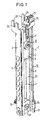
- the height adjustment device according to the invention shown in Fig. 1 for the deflection fitting of a seat belt includes a vertical, for example on the B-pillar Motor vehicle to be mounted rail 1, which two in Cross-section C-shaped side legs 2, the the rear of the rail with each other via a rear wall 3 are connected.
- a vertical for example on the B-pillar Motor vehicle to be mounted rail 1
- two in Cross-section C-shaped side legs 2 the the rear of the rail with each other via a rear wall 3 are connected.
- each Locking receptacles 4 provided, as shown, for example by expressing corresponding sections 5 of the lateral leg 2 can be generated.
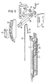
- the lower housing part 7 is slidably guided along the rail 1.
- the housing 6 takes a pawl 8, which together with the upper housing part 9 relative to the lower housing part 7 around a central one Axis I is rotatable.
- pawl 8 provided with recesses 26, in which corresponding, in Upper housing part 9 provided, not shown here Intervene projections.
- One of the two recesses 26 and the associated projection can be compared to the central one Axis I may be misaligned for incorrect assembly by turning pawl 8 and upper housing part by 180 ° to prevent each other.
- the pawl 8 has a laterally projecting nose 10 as well as a central bushing 11, in which a how out Fig. 3 can be seen, stepped pin 12 with its narrower section 13 is inserted with a press fit.
- the narrower section 13 is designed as a threaded bushing, which through a central passage 14 in the upper housing part 9 is performed and as a bearing for a corresponding Threaded bolt of a deflection fitting, not shown here serves.
- the wider section 15 of the tiered Pin 12 has a diameter that is related to the diameter adapted a recess 16 in the lower housing part 7 is so that the wider portion 15 of the stepped pin 12 with the recess 16 in the lower housing part as a pivot bearing for the pawl 8 and the upper housing part 9 cooperates.
- the upper housing part 9 has in its above the bushing 14 located section a receptacle 17 for the end 18 of a Bowden cable 19, which has a deflection device 20 led from above to the upper housing part 9 is.
- the end 18 of the Bowden cable 19 has a thickening 21 provided which has an associated edge in the receptacle 17 engages in the upper housing part 9. How to in particular 4 can be seen, the receptacle 17 for the Bowden cable 19 opposite the central axis I, around which the Upper housing part 9 is rotatable, horizontally offset arranged.
- the deflection device 20 equipped with a pulley 27, about which the Bowden cable 19 is guided. That way the friction when operating the Bowden cable 19 is reduced.
- this is End 28 of the jacket of the Bowden cable 19 in a side the spring bearing 25 provided receptacle 29 mounted.
- the spring bearing 25 has a central passage 30, through which a fastening bolt 31 with interposition a snap ring 32 can be passed through to this Assign the lower end of the rail 1 to the motor vehicle Fasten.
- the upper end of the rail 1 is perpendicular to two Rail-level approaches 33 provided in which in each case an upwardly open slot 34 is formed. With these slots 34, the rail 1 is in a corresponding intended receptacle on the motor vehicle can be used. For fastening the rail 1 in the motor vehicle is therefore only a single fastening bolt 31 is required.
- the Jacket end 28 outstanding length of the Bowden cable 19 accordingly chosen, this automatically depending from the position of the associated vehicle seat.
- the Connection to the vehicle seat is provided so that when the vehicle seat is in the foremost position greatest length of the Bowden cable 19 is present, so that the housing 6 with the bearing 12 for the deflection fitting due to the force the coil spring 23 in the lowest position in the rail 1 is moved while in the rearmost position of the vehicle seat the Bowden cable 19, the housing 6 with the on the jack 8 existing bearings 12 for the deflection fitting against Force of the coil spring 23 pulls into the uppermost position.
- Around different displacement of the vehicle seat and Compensating the deflection fitting can be a for the Bowden cable Translation device may be provided. When moving of the housing 6 acts without loading the bearing 12 the pawl 8, as stated, no resulting torque, so that the pawl 8 in its height adjustment disengaged position remains.
- the device according to the invention thus makes it simple built, automatically height-adjustable device for Storage of the upper fastening or deflection fitting for a seat belt, which in the event of an accident quick and safe blocking of the deflection fitting guaranteed. Few components are required, which are also up to on the upper housing part 9 for both left-hand and also for right-hand installation in a motor vehicle can be used, both the manufacturing cost decreased as well as warehousing and assembly simplified.
- the height of the deflection fitting can Deflection device 20 at the top of the rail 1 so be arranged that the distance of the guide roller 27 from upper end of the rail 1 is manually adjustable.
- the path of the Bowden cable 19 is increased extended to receive 17 in the upper housing part 9, so that with the seating position unchanged, the housing 6 with the bearing 12 is displaced upwards for the deflection fitting.
- the housing 6 by reducing the distance to be moved down.
- FIG. 5 shows such a deflection device 20 additionally Manually adjustable deflection element for the Bowden cable 19.
- a deflection element is one in one Lever element 35 provided deflection roller 36 is provided which the Bowden cable 19 rotates.
- the lever element 35 is on its one, tapered end 38 by a Detent guide 39 guided and 38 at this end attachable actuator 37.
- the other end 40 of the Lever element 35 is rotatably mounted on a pin 41, which is housed in a housing 42.
- Housing 42 has a spring 43 anchored at one end, the other end engages the lever element 35 and this is loaded into its lower swivel position.
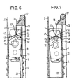
- a bracket 44 with two resilient legs 45, 46 provided that one leg 45 on the Jack 8 and with its other leg 46 on the Slider 7 supports.
- the bracket 44 sits in one a contact edge 47 for the legs 45, 46 of the bracket 44 forming recess 48 of the pawl 8, which is dimensioned so that the bracket 44 with its two legs 45, 46 between an open position in which the legs 45, 46 abut the contact edge 47, and a spread Position in which the two legs 45, 46 continue are pivoted apart, is movable.
- the recess 48 opens on one side into a side opening 49 in the Pawl 8, through which one leg 46 of the bracket 44 in Pick out spread position and on the Can support slide 7.
- the recess 48 for the bracket 44 is in the area of Receptacle 17 arranged for the end 18 of the Bowden cable 19, that the thickening 21 of the Bowden cable 19 when inserted Bowden cable comes to rest in the recess 48.
- the Bowden cable 19 is not only in the recording 17 but at the same time suspended in the appropriately designed bracket 44, so that the Bowden cable 19 in the tensioned state Bracket 44 against the contact edge formed by the recess 48 47 pulls.
- the in. Acts as a counterforce opposite direction attacking on the pawl 8 Coil spring 23.
- This leg 46 thereby supports itself on the opposite inner wall of the Slider 7 from so that over the other leg 45 of the Bracket 44 is applied to the pawl 8 a pivoting force.
- This pivoting force acts in the latching direction of the pawl 8, so that the pawl 8 engages in one of the locking receptacles 4 and the slider with the bearing 12 for the deflection fitting against another shift is blocked.
Landscapes
- Engineering & Computer Science (AREA)
- Mechanical Engineering (AREA)
- Seats For Vehicles (AREA)
- Automotive Seat Belt Assembly (AREA)
Description
Die vorliegende Erfindung betrifft eine Einrichtung zur automatisch höhenverstellbaren Lagerung des oberen Befestigungs- oder Umlenkbeschlages für einen Sicherheitsgurt in einem Fahrzeug, mit einer im wesentlichen vertikal angeordneten Schiene, welche seitliche Rastaufnahmen aufweist, mit einem längs der Schiene verschiebbar geführten Gleitstück, in welchem eine Klinke mit einer seitlich vorstehenden Einrastnase zwischen einer Einraststellung und einer Ausraststellung um eine zur Schienenlängsrichtung senkrechte Achse verschwenkbar gelagert ist, mit einem an der Klinke in der einen Verschieberichtung angreifenden, in Abhängigkeit von der Sitzstellung des zugeordneten Fahrzeugsitzes gesteuerten Verstellelement und mit einem mit dem Gleitstück beweglichen Lager für den Umlenkbeschlag, welches derart an der Klinke angreift, daß die Klinke bei einer Belastung des Lagers durch den Gurt in ihre Einraststellung verschwenkt wird.The present invention relates to a device for automatically height-adjustable storage of the upper fastening or deflection fitting for a seat belt in a vehicle with a substantially vertically arranged Rail, which has side catches with a sliding piece that can be moved along the rail, in which a pawl with a laterally protruding locking lug between an engagement position and an engagement position about an axis perpendicular to the longitudinal direction of the rail is pivotally mounted, with a on the jack in the attacking a displacement direction, depending on controlled the seat position of the assigned vehicle seat Adjustment element and with a movable with the slider Bearing for the deflection fitting, which is so on the pawl attacks that the pawl when the bearing is loaded is pivoted into its locked position by the belt.
Eine derartige Einrichtung ist beispielsweise aus der DE 38 02 323 C2 bekannt. Bei dieser bekannten Einrichtung ist die Klinke um einen durch das Gleitstück vorgegebenen Schwenkpunkt verschwenkbar in dem Gleitstück gelagert. Auf der einen Seite des Schwenkpunktes greift an der Klinke das Verstellelement in der einen Schwenkrichtung an, während sich die Klinke auf der anderen Seite des Schwenkpunktes an einem in der umgekehrten Schwenkrichtung wirkenden Rückstellelement abstützt. Hierdurch ist bei einer Verschiebung des Gleitstücks längs der Schiene ohne Belastung des Lagers für den Umlenkbeschlag gewährleistet, daß die Klinke in ihrer Ausraststellung verbleibt. Such a device is for example from the DE 38 02 323 C2 known. With this known device is the pawl by a predetermined by the slider Pivot point pivotally mounted in the slider. On one side of the pivot point grips the handle Adjustment element in one pivot direction while the pawl on the other side of the pivot point a return element acting in the reverse direction of pivoting supported. This causes a shift the slider along the rail without loading the bearing for the deflection fitting ensures that the pawl in remains in its disengaged position.
Das Lager für den Umlenkbeschlag ist bei dieser bekannten Einrichtung mit dem Gleitstück fest verbunden. Bei einer Belastung des Lagers, wie sie insbesondere bei einem Unfall auftritt, wird daher das Gleitstück mit Schwenkpunkt in der Schiene nach unten bewegt, während die Klinke auf der einen Seite des Schwenkpunktes von dem durch die Sitzstellung festgelegten Verstellelement gehalten wird. Dadurch verschwenkt die Klinke und rastet in eine der seitlichen Rastaufnahmen der Schiene ein, so daß das Gleitstück mit dem Lager für den Umlenkbeschlag gegen eine weitere Verschiebung längs der Schiene blockiert ist.The bearing for the deflection fitting is known in this Device firmly connected to the slider. At a Load on the bearing, especially in the event of an accident occurs, therefore the slider with pivot point in the Rail moves down while the latch is on one Side of the pivot point from that through the sitting position fixed adjustment element is held. Thereby pivots the latch and snaps into one of the side Locking recordings of the rail so that the slider with the Bearing for the deflection fitting against further displacement is blocked along the rail.
Um bei einer derartigen Einrichtung sicherzustellen, daß das Gleitstück nicht nur in der einen Verschieberichtung sondern auch in der entgegengesetzten Verschieberichtung an die gewünschte Position automatisch verschoben werden kann, ist ein an dem Gleitstück in der entsprechend anderen Verschieberichtung angreifendes zusätzliches Rückstellelement erforderlich. Insgesamt ergibt sich damit eine relativ aufwendige Konstruktion, was sich sowohl auf die Herstellungskosten als auch auf die Funktionssicherheit der Einrichtung negativ auswirkt.To ensure in such a facility that the Slider not only in one direction but also also in the opposite direction to the desired position can be moved automatically one on the slider in the corresponding other direction of displacement attacking additional reset element required. Overall, this results in a relatively complex process Construction, which affects both manufacturing costs also negative on the functional reliability of the facility effect.
Der vorliegenden Erfindung liegt daher die Aufgabe zugrunde, eine Einrichtung der genannten Art so weiterzubilden, daß diese Nachteile nicht auftreten. Insbesondere soll die Einrichtung, trotz Gewährleistung einer sicheren Verschiebung des Gleitstücks in beiden Richtungen, vom Aufbau her vereinfacht werden, um die Herstellungskosten zu senken und die Funktionssicherheit zu erhöhen.The present invention is therefore based on the object to develop a device of the type mentioned so that these disadvantages do not occur. In particular, the facility, despite ensuring a safe shift of the slider in both directions, simplified in structure to reduce manufacturing costs and the Increase functional reliability.
Diese Aufgabe wird bei einer Einrichtung das eingangs genannten Art erfindungsgemäß dadurch gelöst, daß ein an der Klinke in der anderen Verschieberichtung angreifendes Rückstellelement vorgesehen ist, und daß das Verstellelement und das Rückstellelement an der Klinke an zwei auf derselben Seite der Schwenkachse angeordneten Punkten angreifen.This object is achieved in a device of the type mentioned in the present invention in that a attacking the handle in the other direction of displacement Restoring element is provided, and that the adjusting element and the return element on the pawl on two on the same Attack the points on the side of the swivel axis.
Durch die Anordnung des Rückstellelements und des Verstellelements derart, daß sie an der Klinke an auf derselben Seite der Schwenkachse angeordneten Punkten in entgegengesetzter Richtung angreifen, ist sichergestellt, daß bei einer Betätigung des Verstellelements kein resultierendes Drehmoment auf die Klinke wirkt, die Klinke also während der Verschiebung des Gleitstücks ohne Belastung des Lagers für den Umlenkbeschlag in ihrer Ausraststellung verbleibt. Das erfindungsgemäß vorgesehene Rückstellelement hat also eine Doppelfunktion. Zum einen überträgt das Rückstellelement auf das Gleitstück eine dem Verstellelement entgegenwirkende Verschiebekraft und zum anderen verhindert das Rückstellelement ein Einrasten der Klinke während des Verstellens der Einrichtung, also bei unbelastetem Lager. Ein das Einrasten verhinderndes separates Rückstellelement kann daher entfallen. Damit erhält man eine in der Funktion verbesserte und dennoch im Aufbau einfache Einrichtung, die sich durch verringerte Herstellungskosten und erhöhte Haltbarkeit auszeichnet, denn es sind weniger Teile vorhanden, die einem Verschleiß unterliegen bzw. ausfallen können.By arranging the reset element and the adjusting element such that they are on the jack on the same Points arranged on the side of the pivot axis in opposite directions Attack direction, it is ensured that at an actuation of the adjusting element does not result Torque acts on the jack, so the jack during Movement of the slider without loading the bearing for the deflection fitting remains in its disengaged position. The Reset element provided according to the invention thus has a Dual function. On the one hand, the reset element transfers the slider counteracting the adjusting element The restoring element prevents displacement and secondly a latching of the pawl during the adjustment of the Establishment, i.e. with the warehouse unloaded. On snapping Preventing separate reset element can therefore be omitted. This gives you an improved in function and nevertheless simple in construction, which was reduced by Manufacturing costs and increased durability, because there are fewer parts that are subject to wear subject to or fail.
Nach einer Ausgestaltung der Erfindung ist das Lager für den Umlenkbeschlag an der Klinke angeordnet, wobei die Anordnung zu dem Angriffspunkt des Verstellelements horizontal versetzt vorgesehen ist. Diese versetzte Anordnung bewirkt, daß bei einer Belastung des Lagers für den Umlenkbeschlag die Klinke relativ zu dem Gleitstück in ihre Einraststellung verschwenkt wird, denn der vom Gurt auf das Lager übertragenen Zugbewegung nach unten wirkt das durch die Sitzstellung festgelegte Verstellelement entgegen. Die vom Lager aufgenommene Kraft wird dadurch direkt auf die Klinke übertragen, so daß das Gleitstück nicht für diese hohe Kraft ausgelegt sein muß. An dem Gleitstück ist an sich nicht einmal ein Drehlager erforderlich, obwohl ein solches nach einer bevorzugten Ausgestaltung der Erfindung vorgesehen ist.According to one embodiment of the invention, the bearing for the Deflection fitting arranged on the pawl, the arrangement offset horizontally to the point of attack of the adjusting element is provided. This staggered arrangement causes when the bearing for the deflection fitting is loaded Pawl in its locked position relative to the slider is pivoted, because the one transferred from the belt to the bearing Pulling movement downwards works through the sitting position fixed adjustment element counter. The one picked up by the camp This transmits power directly to the jack, so that the slider is not designed for this high force have to be. There is not even one on the slide Pivot bearing required, although after one preferred embodiment of the invention is provided.
Nach einer weiteren Ausgestaltung der Erfindung ist das an der Klinke angeordnete Lager für den Umlenkbeschlag auf der Drehachse der Klinke im Gleitstück vorgesehen. Eine vom Gurt auf das Lager für den Umlenkbeschlag übertragene Kraft greift daher vertikal nach unten an der Drehlagerachse an und versucht, die Klinke längs der Schiene nach unten zu verschieben. Aufgrund des zum Lager des Umlenkbeschlages versetzt an der Klinke angreifenden Verstellelements ergibt sich dabei ein resultierendes Drehmoment, welches zu einem Verschwenken der Klinke und deren Einrasten in die seitlichen Rastaufnahmen der Schiene führt.According to a further embodiment of the invention, this is on the pawl arranged bearing for the deflection fitting on the Axis of rotation of the pawl provided in the slider. One off the belt force transmitted to the bearing for the deflection fitting therefore attacks vertically downwards on the pivot axis and tries to pull the latch down along the rail move. Due to the bearing of the deflection fitting staggered on the pawl adjusting element results resulting torque, which leads to a Swiveling the pawl and snapping it into place lateral snap-in recordings of the rail leads.
Nach einer weiteren Ausgestaltung der Erfindung weist die Klinke eine Durchführung auf, durch welche ein längsgestufter Zapfen mit seinem schmaleren, als Lager für den Umlenkbeschlag ausgebildeten Abschnitt hindurchgeführt ist, wobei der breitere Abschnitt des Zapfens als Drehlagerzapfen ausgebildet ist, welcher in einer entsprechenden kreisförmigen Ausnehmung des Gleitstücks drehbar gelagert ist. Durch diese Ausgestaltung wird zum einen eine einfache Drehlagerung der Klinke im Gleitstück bewirkt. Zum anderen hat die gestufte Ausgestaltung des Zapfens den Vorteil, daß der Zapfen bei einer Belastung des Umlenkbeschlags durch den Gurt nicht aus der Klinke herausgezogen werden kann. Um auch bei normalem Betrieb der Einrichtung einen sicheren Sitz des Lagers für den Umlenkbeschlag in der Klinke zu gewährleisten, ist der gestufte Zapfen mit seinem schmaleren Abschnitt bevorzugt mit einem Preßsitz in die Klinke eingesetzt. According to a further embodiment of the invention, the Click a bushing through which a longitudinally stepped Pin with its narrower than a bearing for the deflection fitting trained section is passed, wherein the wider section of the pin than the pivot pin is formed, which is in a corresponding circular Recess of the slider is rotatably mounted. By on the one hand, this configuration becomes a simple pivot bearing the pawl in the slider causes. On the other hand, the tiered design of the pin has the advantage that the Pin when the deflection fitting is loaded by the Belt cannot be pulled out of the pawl. Too too during normal operation of the device a secure fit of the To ensure the bearing for the deflection fitting in the pawl, is the stepped pin with its narrower Section preferably with a press fit into the pawl used.
Nach einer weiteren Ausgestaltung der Erfindung ist die Klinke in einem zweiteiligen Gehäuse gelagert, dessen Gehäuseunterteil als Gleitstück dient und dessen Gehäuseoberteil zusammen mit der Klinke gegenüber dem Gehäuseunterteil in der Schienenebene verschwenkbar ist, wobei das Verstellelement und das Rückstellelement am Gehäuseoberteil angreifen. Diese Ausgestaltung ermöglicht eine einfache Anbringung des Verstellelements und des Rückstellelements an dem Gehäuseoberteil, welches insbesondere aus Kunststoff hergestellt sein kann, und zugleich eine Ausbildung der Klinke aus einem besonders stabilen Material, insbesondere Metall.According to a further embodiment of the invention Jack stored in a two-part housing, the The lower part of the housing serves as a slider and the upper part of the housing together with the latch opposite the lower part of the housing is pivotable in the rail plane, which Adjustment element and the reset element on the upper part of the housing attack. This configuration enables simple Attachment of the adjusting element and the restoring element the upper housing part, which is made in particular of plastic can be made, and at the same time training the Jack made of a particularly stable material, in particular Metal.
Als Verstellelement zur Verschiebung des Gleitstücks längs der Schiene dient bevorzugt ein Seil, insbesondere ein Bowdenzug. Der Bowdenzug ist dabei bevorzugt über eine Umlenkeinrichtung geführt und greift von oben her an der Klinke oder am Gehäuseoberteil an. Das andere Ende des Bowdenzuges wird beim Verschieben des Fahrzeugsitzes derart bewegt, daß der Bowdenzug in der vordersten Sitzstellung am weitesten ausgefahren ist, so daß sich der Umlenkbeschlag in seiner untersten Stellung befindet. Umgekehrt zieht der Bowdenzug den Umlenkbeschlag in seine oberste Stellung, wenn sich der Fahrzeugsitz in seiner hintersten Stellung befindet. Am unteren Ende der Klinke oder des Gehäuseoberteils greift bei dieser Ausgestaltung entsprechend das Rückstellelement an, welches den Umlenkbeschlag daher in seine unterste Stellung vorspannt. Beim Ausfahren des Bowdenzuges wird dadurch sichergestellt, daß der Umlenkbeschlag in die gewünschte Stellung nach unten verschoben wird.As an adjustment element for sliding the slider lengthways the rail is preferably a rope, in particular a Bowden cable. The Bowden cable is preferably via a deflection device guided and grips the handle from above or on the upper part of the housing. The other end of the Bowden cable is moved when the vehicle seat is moved, that the Bowden cable in the foremost seating position on is extended as far as possible, so that the deflection fitting is in its lowest position. Conversely, the Bowden cable the deflection fitting into its uppermost position, if the vehicle seat is in its rearmost position. At the lower end of the jack or upper part of the housing grips the restoring element accordingly in this embodiment which therefore deflects the fitting into its lowest Prestressed position. When extending the Bowden cable thereby ensuring that the deflection fitting in the desired Position is shifted down.
Nach einer weiteren Ausgestaltung der Erfindung ist als Rückstellelement eine Spiralfeder vorgesehen, wobei die Spiralfeder bevorzugt in einer in der Schiene verankerbaren Federhülse gelagert ist, welche eine zentrale Durchführung für einen Befestigungsbolzen aufweist. Die Federhülse dient somit zusätzlich zur Lagerung der Spiralfeder auch zur Befestigung der Schiene am Fahrzeug. Des weiteren kann die Federhülse auch mit einer seitlichen Aufnahme für das Ende des Mantels des Bowdenzugs versehen sein, so daß die Federhülse noch eine weitere Funktion übernimmt. Durch diese Mehrzweckfunktion der Federhülse werden die Herstellungsund Montagekosten weiter gesenkt.According to a further embodiment of the invention is as Return element provided a coil spring, the Coil spring preferably in one that can be anchored in the rail Spring sleeve is mounted, which is a central implementation for a fastening bolt. The spring sleeve serves thus in addition to the storage of the coil spring Attaching the rail to the vehicle. Furthermore, the Spring sleeve also with a side mount for the end of the jacket of the Bowden cable, so that the spring sleeve performs another function. Through this Multipurpose function of the spring sleeve are the manufacturing and Assembly costs further reduced.
Nach einer weiteren Ausgestaltung der Erfindung ist an der Klinke ein Spreizfederelement vorgesehen, welches durch die zwischen Verstellelement und Rückstellelement wirkende Spannkraft in ungespreizter Stellung gehalten wird, wobei das Spreizfederelement so zwischen Klinke und Gleitstück oder zwischen Klinke und Schiene angeordnet ist, daß die Klinke bei Wegfall der Spannkraft von dem Spreizfederelement in Richtung auf ihre Einraststellung belastet wird. Durch das Spreizfederelement wird vorteilhafterweise sichergestellt, daß die Klinke auch bei einem Defekt des Verstellelements oder des Rückstellelements oder eines damit verbundenen Teils, beispielsweise bei einem Bruch oder Aushängen des Bowdenzuges, sicher einrastet und das Gleitstück mit dem Lager für den Umlenkbeschlag gegen eine vertikale Verschiebung blockiert wird. Bei einem Defekt des Verstellelements fällt die Spannkraft weg, so daß das Spreizfederelement aufspreizt und die Klinke in ihre Einraststellung verschwenkt wird.According to a further embodiment of the invention Pawl provided an expansion spring element, which by the clamping force acting between the adjusting element and the restoring element is held in an open position, the Spreading spring element between pawl and slide or is arranged between the pawl and rail that the pawl in the event of loss of the clamping force from the spreading spring element in Direction is loaded onto its latching position. By the Spreading spring element is advantageously ensured that the pawl even if the adjusting element is defective or the reset element or an associated Partly, for example if the Bowden cable, clicks into place and the slide with the bearing for the deflection fitting against vertical displacement is blocked. If the adjustment element is defective the clamping force away, so that the spreading spring element spreads and the pawl is pivoted into its locked position.
Bevorzugt ist das Spreizfederelement als Bügel mit zwei federnden Schenkeln ausgebildet, der sich in gespreiztem Zustand mit seinem einen Schenkel an der Klinke und mit seinem anderen Schenkel am Gleitstück abstützt, wobei die Spannweite des Bügels in Abhängigkeit von der Spannkraft veränderlich ist. Bei vorhandener Spannkraft werden die beiden Schenkel des Bügels so weit zusammengeschwenkt, daß der Bügel keine Verschwenkkraft auf die Klinke ausübt. Fällt die Spannkraft weg, spreizt der Bügel auf und belastet die Klinke in Einrastrichtung.The spreading spring element is preferred as a bracket with two resilient legs formed in spread Condition with one leg on the handle and with supports his other leg on the slider, the Span of the bracket depending on the tension is changeable. If there is tension, the swiveled both legs of the bracket so far that the bracket does not exert any pivoting force on the latch. falls the tension away, the bracket spreads and loads the Pawl in the locking direction.
Nach einer weiteren Ausgestaltung der Erfindung weist die Klinke eine Anlagekante mindestens für jeweils einen Teil der beiden Schenkel des Bügels auf und wird der Bügel durch die Spannkraft so gegen die Anlagekante gehalten, daß die beiden Schenkel so weit zusammengeschwenkt sind, daß die Klinke von dem Bügel entlastet ist. Die Anlagekante kann dabei bevorzugt durch eine Ausnehmung im Bereich des Angriffspunkts des Verstellelements gebildet sein, und das Verstellelement kann bevorzugt an der Verbindungsstelle der beiden Schenkel des Bügels angreifen und diesen gegen die Anlagekante ziehen. Durch diese Ausgestaltung ist das Spreizfederelement in geschickter Weise in die Klinke integriert und wird durch das Verstellelement, beispielsweise den Bowdenzug, in ungespreizter Stellung gehalten, solange kein Bruch auftritt. Bei einem Bruch des Bowdenzugs oder einem unbeabsichtigten Aushängen desselben, fällt dagegen die Zugkraft des Bowdenzugs auf den Bügel weg, so daß dieser aufspreizt und durch seine beiden Schenkel die Klinke in Einrastrichtung belastet.According to a further embodiment of the invention, the Click a contact edge for at least one part at a time of the two legs of the bracket and the bracket is through the tension is held against the contact edge so that the two legs are pivoted so far that the Jack is relieved of the bracket. The contact edge can preferably through a recess in the area of the Point of attack of the adjusting element be formed, and that Adjustment element can preferably at the junction of the attack both legs of the bracket and this against the Pull the contact edge. This configuration makes the spreading spring element cleverly integrated into the jack and is by the adjusting element, such as the Bowden cable, held in an open position, as long as none Breakage occurs. If the Bowden cable breaks or if unintentional posting of the same, however, falls Traction of the Bowden cable on the bracket away, so that this spreads and through its two legs the latch in Snap direction loaded.
Um bei einer Einrichtung zur automatischen Höhenverstellung des Umlenkbeschlages zusätzlich eine individuelle Anpassung der Höhe des Umlenkbeschlages zu ermöglichen, ist nach einer weiteren Ausgestaltung der Erfindung vorgesehen, daß der Abstand der Umlenkeinrichtung für den Bowdenzug vom oberen Ende der Schiene manuell verstellbar ist. Bei jeder über die Sitzstellung eingestellten Länge des Bowdenzuges kann somit die dadurch vorgegebene Höhe des Umlenkbeschlages über einen bestimmten Bereich zusätzlich verändert werden. Damit kann der Tatsache Rechnung getragen werden, daß die von einer Person gewählte Sitzstellung nicht immer vollständig mit ihrer Körpergröße bzw. Schulterhöhe korreliert. In order for a device for automatic height adjustment individual adjustment of the deflection fitting the height of the deflection fitting is possible after one Another embodiment of the invention provided that the Distance of the deflection device for the Bowden cable from the upper one End of the rail is manually adjustable. With everyone about the Seat position adjusted length of the Bowden cable can thus the predetermined height of the deflection fitting certain area can also be changed. So that can take into account the fact that those of a Person's chosen seating position is not always complete their height or shoulder height correlated.
Für die zusätzliche manuelle Verstellung weist die Umlenkeinrichtung nach einer weiteren Ausgestaltung der Erfindung ein um eine im wesentlichen horizontale Achse drehbar gelagertes Hebelelement auf, welches ein Umlenkelement für den Bowdenzug und ein Betätigungselement trägt, wobei das Umlenkelement näher an der Drehachse des Hebelelementes angeordnet ist als das Betätigungselement. Auf diese Weise wird die für eine manuelle Verstellung erforderliche Kraft vorteilhafterweise gering gehalten. Dies ist insbesondere auch deshalb wichtig, weil bei der manuellen Verstellung des Umlenkelements der höhenverstellbare Umlenkbeschlag den doppelten Weg zurücklegt wie das Betätigungselement.For the additional manual adjustment, the deflection device according to a further embodiment of the invention one rotatable about a substantially horizontal axis stored lever element, which is a deflecting element for carries the Bowden cable and an actuator, which Deflection element closer to the axis of rotation of the lever element is arranged as the actuating element. In this way becomes the force required for manual adjustment advantageously kept low. This is particularly so also important because when manually adjusting the Deflection elements of the height-adjustable deflection fitting travel twice as the actuator.
Zur Umlenkung des Bowdenzugs ist nach einer weiteren Ausgestaltung der Erfindung bevorzugt eine Umlenkrolle vorgesehen. Die bei der Betätigung des Bowdenzugs auftretende Reibung wird dadurch verringert, was einerseits die Funktionssicherheit der Einrichtung erhöht und andererseits eine zusätzliche manuelle Höhenverstellung erleichtert.According to a further embodiment, the Bowden cable is deflected the invention preferably a deflection roller is provided. The one that occurs when the Bowden cable is operated This reduces friction, which on the one hand improves functional reliability the facility increased and on the other hand a additional manual height adjustment made easier.
Durch an zwei einander gegenüberliegenden Seiten der Schiene vorgesehene Rastaufnahmen ist die erfindungsgemäße Einrichtung für beidseitige Benutzung in einem Kraftfahrzeug geeignet. Alle Teile der erfindungsgemäßen Einrichtung mit Ausnahme des Gehäuseoberteils können dann sowohl für linkswie auch für rechtsseitigen Einbau verwendet werden.By on two opposite sides of the rail The intended snap-in receptacle is the device according to the invention for double-sided use in a motor vehicle suitable. All parts of the device according to the invention Exception of the upper part of the housing can then be used for both can also be used for right-hand installation.
An ihrem oberen Ende ist die Schiene bevorzugt mit Schlitzen zum Einhängen in eine am Fahrzeug vorhandene Aufnahme versehen. Die Montage der erfindungsgemäßen Einrichtung wird dadurch erheblich erleichtert. Die Schiene wird in die beispielsweise an der B-Säule des Fahrzeugs vorhandene Aufnahme von unten her eingehängt, und muß anschließend nur noch mittels des einzigen durch die Federhülse geführten Befestigungsbolzens an der B-Säule befestigt werden. At its upper end, the rail is preferably with slots for hanging in an existing holder on the vehicle Mistake. The assembly of the device according to the invention will thereby greatly facilitated. The rail is in the for example on the B-pillar of the vehicle Mounted from below, and then only has to still by means of the only one guided through the spring sleeve Fastening bolt to be attached to the B-pillar.
Ausführungsbeispiele der Erfindung sind in der Zeichnung dargestellt und werden nachfolgend beschrieben. Es zeigen, jeweils in schematischer Darstellung:
- Fig. 1
- eine perspektivische Draufsicht auf eine erfindungsgemäße Einrichtung,
- Fig. 2
- eine Explosionsdarstellung der Einrichtung von Fig. 1,
- Fig. 3
- ein Detail von Fig. 2 in vergrößerter Seitenansicht,
- Fig. 4
- eine ebenfalls vergrößerte Vorderansicht auf ein anderes Detail von Fig. 2,
- Fig. 5
- eine vergrößerte Explosionsdarstellung einer Variante der erfindungsgemäßen Einrichtung,
- Fig. 6
- einen Schnitt durch einen Teil einer weiteren Variante der erfindungsgemäßen Einrichtung in gespanntem Zustand, und
- Fig. 7
- eine Fig. 6 entsprechende Darstellung dieser Variante in gelöstem Zustand.
- Fig. 1
- a top perspective view of a device according to the invention,
- Fig. 2
- 2 shows an exploded view of the device from FIG. 1,
- Fig. 3
- 3 shows a detail of FIG. 2 in an enlarged side view,
- Fig. 4
- 2 also shows an enlarged front view of another detail from FIG. 2,
- Fig. 5
- an enlarged exploded view of a variant of the device according to the invention,
- Fig. 6
- a section through part of a further variant of the device according to the invention in a tensioned state, and
- Fig. 7
- a Fig. 6 corresponding representation of this variant in the released state.
Die in Fig. 1 dargestellte erfindungsgemäße Höhenverstelleinrichtung
für den Umlenkbeschlag eines Sicherheitsgurtes
umfaßt eine vertikal, beispielsweise an der B-Säule eines
Kraftfahrzeugs anzubringende Schiene 1, welche zwei im
Querschnitt C-förmige seitliche Schenkel 2 aufweist, die an
der Schienenrückseite über eine Rückwand 3 miteinander
verbunden sind. In den seitlichen Schenkeln 2 sind jeweils
Rastaufnahmen 4 vorgesehen, die, wie dargestellt, beispielsweise
durch Ausdrücken entsprechender Abschnitte 5 der
seitlichen Schenkel 2 erzeugt werden können.The height adjustment device according to the invention shown in Fig. 1
for the deflection fitting of a seat belt
includes a vertical, for example on the B-pillar
Motor vehicle to be mounted
In die Schiene 1 ist ein, wie man in Fig. 2 erkennen kann,
zweiteiliges Gehäuse 6 eingesetzt, dessen Gehäuseunterteil 7
längs der Schiene 1 verschiebbar geführt ist. Das Gehäuse 6
nimmt eine Klinke 8 auf, welche zusammen mit dem Gehäuseoberteil
9 relativ zum Gehäuseunterteil 7 um eine zentrale
Achse I verdrehbar ist. Um ein Verdrehen des Gehäuseoberteils
gegenüber der Klinke 8 zu verhindern, ist die Klinke 8
mit Ausnehmungen 26 versehen, in welche entsprechende, im
Gehäuseoberteil 9 vorgesehene, hier nicht dargestellte
Vorsprünge eingreifen. Einer der beiden Ausnehmungen 26 und
der zugehörige Vorsprung können dabei gegenüber der zentralen
Achse I versetzt sein, um einen fehlerhaften Zusammenbau
durch Verdrehen von Klinke 8 und Gehäuseoberteil um 180°
gegeneinander zu verhindern.In the
Die Klinke 8 weist eine seitlich vorstehende Nase 10 auf
sowie eine zentrale Durchführung 11, in welche ein, wie aus
Fig. 3 ersichtlich ist, gestufter Zapfen 12 mit seinem
schmaleren Abschnitt 13 mit Preßsitz eingesetzt ist. Der
schmalere Abschnitt 13 ist als Gewindebuchse ausgebildet,
welche durch eine zentrale Durchführung 14 im Gehäuseoberteil
9 geführt ist und als Lager für einen entsprechenden
Gewindebolzen eines hier nicht dargestellten Umlenkbeschlages
dient. Der breitere Abschnitt 15 des gestuften
Zapfens 12 weist einen Durchmesser auf, der an den Durchmesser
einer Ausnehmung 16 im Gehäuseunterteil 7 angepaßt
ist, so daß der breitere Abschnitt 15 des gestuften Zapfens
12 mit der Ausnehmung 16 im Gehäuseunterteil als Drehlager
für die Klinke 8 und das Gehäuseoberteil 9 zusammenwirkt.The pawl 8 has a laterally projecting
Das Gehäuseoberteil 9 weist in seinem oberhalb der Durchführung
14 gelegenen Abschnitt eine Aufnahme 17 für das Ende
18 eines Bowdenzuges 19 auf, welcher über eine Umlenkeinrichtung
20 von oben her zum Gehäuseoberteil 9 geführt
ist. Das Ende 18 des Bowdenzuges 19 ist mit einer Verdickung
21 versehen, welche eine zugeordnete Kante in der Aufnahme
17 im Gehäuseoberteil 9 hintergreift. Wie man insbesondere
in Fig. 4 erkennen kann, ist die Aufnahme 17 für den
Bowdenzug 19 gegenüber der zentralen Achse I, um welche das
Gehäuseoberteil 9 verdrehbar ist, horizontal versetzt
angeordnet.The upper housing part 9 has in its above the
In der gleichen Richtung gegenüber der zentralen Achse I
horizontal versetzt greift in einer im unteren Abschnitt des
Gehäuseoberteils 9 vorgesehenen Ausnehmung 24 das Ende 22
einer Spiralfeder 23 an, welche mit ihrem anderen Ende in
einer Federaufnahme 25 verankert ist. Die Federaufnahme 25
ist ihrerseits in das untere Ende der Schiene 1 eingesetzt
und an dieser verankert. Die durch die versetzte Anordnung
der Aufnahme 17 und der Ausnehmung 24 am Gehäuseoberteil 9
bei einer Höhenverstellung hervorgerufenen Drehmomente heben
sich gegenseitig auf, so daß ein Verschieben des Gehäuses 6
innerhalb der Schiene 1 ohne ein Verdrehen und damit Einrasten
der Klinke 8 erfolgen kann.In the same direction with respect to the central axis I
horizontally offset engages in a lower section of the
Upper part 9 of the
Wie man in Fig. 1 und 2 erkennen kann, ist die Umlenkeinrichtung
20 mit einer Umlenkrolle 27 ausgerüstet, über
welche der Bowdenzug 19 geführt ist. Auf diese Weise wird
die Reibung bei Betätigung des Bowdenzuges 19 verringert.
Wie man ebenfalls in Fig. 1 und 2 erkennen kann, ist das
Ende 28 des Mantels des Bowdenzuges 19 in einer seitlich an
dem Federlager 25 vorgesehenen Aufnahme 29 gelagert. Zudem
weist das Federlager 25 eine zentrale Durchführung 30 auf,
durch welche ein Befestigungsbolzen 31 unter Zwischenschaltung
eines Sprengrings 32 hindurchführbar ist, um auf diese
Weise das untere Ende der Schiene 1 am Kraftfahrzeug zu
befestigen. As can be seen in FIGS. 1 and 2, the
Das obere Ende der Schiene 1 ist mit zwei senkrecht zur
Schienenebene verlaufenden Ansätzen 33 versehen, in denen
jeweils ein nach oben offener Schlitz 34 ausgebildet ist.
Mit diesen Schlitzen 34 ist die Schiene 1 in eine entsprechende,
am Kraftfahrzeug vorgesehene Aufnahme einsetzbar.
Zur Befestigung der Schiene 1 im Kraftfahrzeug ist daher
lediglich ein einziger Befestigungsbolzen 31 erforderlich.The upper end of the
Zur Höhenverstellung des Umlenkbeschlages wird die über das
Mantelende 28 herausragende Länge des Bowdenzuges 19 entsprechend
gewählt, wobei dies automatisch in Abhängigkeit
von der Position des zugehörigen Fahrzeugsitzes erfolgt. Die
Verbindung mit dem Fahrzeugsitz ist dabei so vorgesehen, daß
bei in vorderster Stellung befindlichem Fahrzeugsitz die
größte Länge des Bowdenzuges 19 vorliegt, so daß das Gehäuse
6 mit dem Lager 12 für den Umlenkbeschlag aufgrund der Kraft
der Spiralfeder 23 in die unterste Stellung in der Schiene 1
bewegt wird, während in der hintersten Stellung des Fahrzeugsitzes
der Bowdenzug 19 das Gehäuse 6 mit dem an der Klinke
8 vorhandenen Lager 12 für den Umlenkbeschlag entgegen der
Kraft der Spiralfeder 23 in die oberste Stellung zieht. Um
unterschiedliche Verschiebewege des Fahrzeugsitzes und des
Umlenkbeschlages auszugleichen, kann für den Bowdenzug eine
Übersetzungseinrichtung vorgesehen sein. Bei der Verschiebung
des Gehäuses 6 ohne Belastung des Lagers 12 wirkt auf
die Klinke 8, wie ausgeführt, kein resultierendes Drehmoment,
so daß die Klinke 8 bei der Höhenverstellung in ihrer
ausgerasteten Stellung verbleibt.To adjust the height of the deflection fitting, use the
Bei einem Unfall wird die Klinke 8 vom Sicherheitsgurt über
den Umlenkbeschlag und dessen Lager 12 belastet, wobei die
übertragene Kraft stets eine in Schienenrichtung nach unten
gerichtete Komponente aufweist. Dieser die Klinke 8 nach
unten ziehenden Kraft wirkt die Haltekraft des durch die
Sitzstellung festgelegten Bowdenzuges 19 entgegen, die auf
die Klinke zur zentralen Achse I versetzt übertragen wird.
Dadurch entsteht ein auf die Klinke 8 wirkendes resultierendes
Drehmoment, welches die Klinke 8 um die zentrale
Achse I verdreht, bis die Klinke 8 mit ihrer seitlichen Nase
10 in eine der seitlichen Rastaufnahmen 4 der Schiene 1
einrastet. Hierdurch wird eine weitere Bewegung der Klinke 8
und damit des im Lager 12 gelagerten Umlenkbeschlages längs
der Schiene 1 blockiert.In an accident, the pawl 8 from the seat belt
the deflection fitting and its
Die erfindungsgemäße Einrichtung stellt damit eine einfach aufgebaute, automatisch höhenverstellbare Einrichtung zur Lagerung des oberen Befestigungs- oder Umlenkbeschlages für einen Sicherheitsgurt dar, die im Falle eines Unfalles eine schnelle und sichere Blockierung des Umlenkbeschlages gewährleistet. Es sind wenige Bauteile notwendig, die zudem bis auf das obere Gehäuseteil 9 sowohl für linksseitigen als auch für rechtsseitigen Einbau in einem Kraftfahrzeug verwendet werden können, was sowohl die Herstellungskosten erniedrigt als auch die Lagerhaltung und die Montage vereinfacht.The device according to the invention thus makes it simple built, automatically height-adjustable device for Storage of the upper fastening or deflection fitting for a seat belt, which in the event of an accident quick and safe blocking of the deflection fitting guaranteed. Few components are required, which are also up to on the upper housing part 9 for both left-hand and also for right-hand installation in a motor vehicle can be used, both the manufacturing cost decreased as well as warehousing and assembly simplified.
Um zusätzlich zu der automatischen Höhenverstellung in
Abhängigkeit von der Sitzstellung eine individuelle Anpassung
der Höhe des Umlenkbeschlages zu ermöglichen, kann die
Umlenkeinrichtung 20 an der Oberseite der Schiene 1 so
angeordnet sein, daß der Abstand der Umlenkrolle 27 vom
oberen Ende der Schiene 1 manuell einstellbar ist. Durch
Vergrößerung des Abstandes wird der Weg des Bowdenzuges 19
zur Aufnahme 17 im oberen Gehäuseteil 9 verlängert, so daß
bei unveränderter Sitzstellung das Gehäuse 6 mit dem Lager
12 für den Umlenkbeschlag nach oben verschoben wird. Umgekehrt
kann das Gehäuse 6 durch Verringerung des Abstandes
nach unten verschoben werden. In addition to the automatic height adjustment in
Individual adjustment depending on the seating position
the height of the deflection fitting
Fig. 5 zeigt eine solche Umlenkeinrichtung 20 mit zusätzlich
manuell in der Höhe verstellbarem Umlenkelement für den
Bowdenzug 19. Als Umlenkelement ist eine in einem
Hebelelement 35 gelagerte Umlenkrolle 36 vorgesehen, über
welche der Bowdenzug 19 umläuft. Das Hebelelement 35 ist an
seinem einen, verjüngt ausgebildeten Ende 38 durch eine
Rastenführung 39 geführt und trägt an diesem Ende 38 ein
aufsteckbares Betätigungselement 37. Das andere Ende 40 des
Hebelelements 35 ist auf einem Stift 41 drehbar gelagert,
welcher in einem Gehäuse 42 untergebracht ist. In dem
Gehäuse 42 ist eine Feder 43 mit ihrem einen Ende verankert,
deren anderes Ende an dem Hebelelement 35 angreift und
dieses in seine untere Schwenkstellung belastet.5 shows such a
Durch Verschwenken des Hebelelementes 35 um den Stift 41
wird die in dem Hebelelement 35 gelagerte Umlenkrolle 36
angehoben oder abgesenkt. Dabei rastet das Hebelelement 35
in den durch die Rastenführung 39 vorgegebenen Einraststellungen
ein. Durch die Anordnung des Betätigungselementes 37
an dem von der Schwenkachse des Hebelelements 35 abgewandten
Ende 38 steht zur Betätigung des Hebelelementes 35 ein
großer Hebelarm zur Verfügung, so daß die näher an der
Schwenkachse gelagerte Umlenkrolle 36 leicht zusammen mit
dem Umlenkbeschlag angehoben werden kann.By pivoting the
Bei dem in Fig. 6 gezeigten Teilquerschnitt durch eine
weitere Variante der erfindungsgemäßen Vorrichtung ist in
der Klinke 8 ein Bügel 44 mit zwei federnden Schenkeln 45,
46 vorgesehen, der sich mit seinem einen Schenkel 45 an der
Klinke 8 und mit seinem anderen Schenkel 46 an dem
Gleitstück 7 abstützt. Der Bügel 44 sitzt hierzu in einer
eine Anlagekante 47 für die Schenkel 45, 46 des Bügels 44
bildenden Ausnehmung 48 der Klinke 8, die so bemessen ist,
daß der Bügel 44 mit seinen beiden Schenkeln 45, 46 zwischen
einer ungespreizten Stellung, in welcher die Schenkel 45, 46
an der Anlagekante 47 anliegen, und einer gespreizten
Stellung, in welcher die beiden Schenkel 45, 46 weiter
auseinandergeschwenkt sind, beweglich ist. Die Ausnehmung 48
mündet auf einer Seite in eine seitliche Öffnung 49 in der
Klinke 8, durch welche der eine Schenkel 46 des Bügels 44 in
gespreizter Stellung herausgreifen und sich an dem
Gleitstück 7 abstützen kann.In the partial cross section shown in Fig. 6 by a
Another variant of the device according to the invention is in
the pawl 8 a
Die Ausnehmung 48 für den Bügel 44 ist so im Bereich der
Aufnahme 17 für das Ende 18 des Bowdenzugs 19 angeordnet,
daß die Verdickung 21 des Bowdenzugs 19 bei eingesetztem
Bowdenzug in der Ausnehmung 48 zu liegen kommt. Der Bowdenzug
19 ist dabei nicht nur in die Aufnahme 17 sondern zugleich
in den entsprechend ausgestalteten Bügel 44 eingehängt,
so daß der Bowdenzug 19 in gespanntem Zustand den
Bügel 44 gegen die von der Ausnehmung 48 gebildete Anlagekante
47 zieht. Als Gegenkraft wirkt hierbei die in
entgegengesetzter Richtung an der Klinke 8 angreifende
Spiralfeder 23.The
Bei gespanntem Bowdenzug 19 und vorhandener Gegenkraft der
Spiralfeder 23 befindet sich der Bügel 44 also in seiner
gegen die Anlagekante 47 gehaltenen Stellung. Die beiden
Schenkel 45 und 46 des Bügels 44 schwenken dadurch soweit
zusammen, daß sich der Schenkel 46 innerhalb der Klinke 8
befindet und sich nicht am Gleitstück 7 abstützt. Diese
ungespreizte Stellung hält der Bügel 44 unabhängig von der
Verschiebestellung des Bowdenzugs 19 so lange ein, wie die
durch Bowdenzug 19 und Spiralfeder 23 auf die Klinke 8
ausgeübte Spannkraft vorhanden ist. Bei einem Reißen oder
Aushängen des Bowdenzuges, oder auch bei einem Bruch der
Spiralfeder 23, fällt diese Spannkraft weg. Der Bügel 44
wird daher dann nicht mehr gegen die Anlagekante 47 gezogen,
so daß er aufspreizt und mit seinem Schenkel 46 aus der
Öffnung 49 in der Klinke 8 herausgreift. Dieser Schenkel 46
stützt sich dadurch an der gegenüberliegenden Innenwand des
Gleitstücks 7 ab, so daß über den anderen Schenkel 45 des
Bügels 44 auf die Klinke 8 eine Schwenkkraft ausgeübt wird.
Diese Schwenkkraft wirkt in Einrastrichtung der Klinke 8, so
daß die Klinke 8 in eine der Rastaufnahmen 4 einrastet und
das Gleitstück mit dem Lager 12 für den Umlenkbeschlag gegen
eine weitere Verschiebung blockiert wird.When the
Mit geringem Aufwand und ohne zusätzlichen Platzbedarf wird so sichergestellt, daß auch bei einem Bruch oder einem Aushängen des Bowdenzuges oder einem Federbruch ein sicheres Einrasten der Klinke 8 und damit ein Blockieren der vertikalen Verstellung des oberen Umlenkbeschlages eines Sicherheitsgutsystems im Ernstfall gewährleistet ist.With little effort and without additional space This ensures that even in the event of a break or unhinging a safe Bowden cable or a broken spring Locking the pawl 8 and thus blocking the vertical Adjustment of the upper deflection fitting of a security goods system is guaranteed in an emergency.
Claims (19)
- Device for the automatically height-adjustable mounting of the upper fastening or deflection fitting for a seat belt in a vehicle, having an essentially vertically arranged rail (1) which has lateral latching retainers (4), having a slider (7) which is guided displaceably along the rail (1) and in which a catch (8) having a laterally protruding latching lug (10) is mounted in a manner such that it can pivot about an axis (I), which is perpendicular with respect to the longitudinal direction of the rail, between a latching position and a disengaged position, having an adjusting element (19) which acts on the catch (8) in the one direction of displacement and is controlled as a function of the seat position of the associated vehicle seat, and having a bearing (12) for the deflection fitting, the said bearing being movable together with the slider and acting on the catch (8) in such a manner that, when the belt subjects the bearing (12) to a load, the catch (8) is pivoted into its latching position, characterized in that a restoring element (23) acting on the catch (8) in the other direction of displacement is provided, and in that the adjusting element (19) and the restoring element (23) act on the catch (8) at two points (17, 24) arranged on the same side of the pivot axis (I).
- Device according to Claim 1, characterized in that the bearing (12) for the deflection fitting is arranged offset horizontally on the catch (8) with respect to the engagement point (17) of the adjusting element (19).
- Device according to Claim 2, characterized in that the slider (7) has a preferably central rotational mounting (16) for the catch (8).
- Device according to Claim 3, characterized in that the bearing (12) which is present on the catch (8) and is intended for the deflection fitting is provided in the slider (7) on the axis of rotation (I) of the catch (8).
- Device according to Claim 4, characterized in that the catch (8) has a bushing (11) through which a longitudinally stepped journal (12) is guided by its narrower section (13), which is designed as a bearing for the deflection fitting, and in that the wider section (15) of the journal (12) is designed as a rotational bearing journal which is mounted rotatably in a corresponding circular recess (16) of the slider (7).
- Device according to one of the preceding claims, characterized in that the catch (8) is mounted in a two-part housing (6), the housing lower part (7) of which serves as a slider and the housing upper part (9) of which can be pivoted together with the catch (8) with respect to the housing lower part (7) in the plane of the rail, in which case the adjusting element (19) and the restoring element (23) act on the housing upper part (9).
- Device according to one of the preceding claims, characterized in that a cable, in particular a Bowden cable (19), serves as the adjusting element.
- Device according to Claim 7, characterized in that the cable (19) is guided via a deflection device (20) and acts from above on the catch (8) or on the housing upper part (9).
- Device according to one of the preceding claims, characterized in that a spiral spring (23) is provided as the restoring element and is mounted in a spring sleeve (25) which can be secured in the rail (1) and has a central bushing (30) for a fastening bolt (31).
- Device according to Claim 9, characterized in that a lateral retaining (29) for the end (28) of the sheath of the Bowden cable (19) is provided on the spring sleeve (25).
- Device according to one of the preceding claims, characterized in that an expanding spring element (44) is provided on the catch (8) and is held in an unexpanded position by the tensioning force acting between the adjusting element (19) and restoring element (23), and in that the expanding spring element (44) is arranged between the catch (8) and slider (7) or between the catch (8) and rail (1) in such a manner that, when the tensioning force ceases, the catch (8) is loaded by the expanding spring element (44) in the direction of its latching position.
- Device according to Claim 11, characterized in that the expanding spring element is designed as a clip (44) having two resilient legs (45, 46), the clip being supported, in the expanded state, with its one leg (45) on the catch (8) and with its other leg (46) on the slider (7) and its span being changeable as a function of the tensioning force.
- Device according to Claim 12, characterized in that the catch (8) has a bearing edge (47) at least for one part in each case of the two legs (45, 46) of the clip (44), and in that the clip (44) is held against the bearing edge (47) by the tensioning force in such a manner that the two legs are pivoted together to an extent sufficient for the catch (8) to be relieved of the pivoting force of the clip (44).
- Device according to Claim 13, characterized in that the bearing edge (47) is formed by a recess (48) in the region of the engagement point (17) of the adjusting element (19) on the catch (8), and in that the adjusting element (19) acts on the connecting point (50) of the two legs (45, 46) of the clip (44) and pulls the latter against the bearing edge (47).
- Device for the automatically height-adjustable mounting of the upper fastening or deflection fitting for a seat belt in a vehicle, having an essentially vertically arranged rail (1) which has lateral latching retainers (4), having a slider (7) which is guided displaceably along the rail (1) and in which a catch (8) having a laterally protruding latching lug (10) is mounted in a manner such that it can pivot about an axis (I), which is perpendicular with respect to the longitudinal direction of the rail, between a latching position and a disengaged position, and having a Bowden cable (19) which engages on the catch (8) from above in the direction of displacement and is guided via a deflection device (20) present above the rail (1), according to one of the preceding claims, characterized in that the distance of the deflection device (20) for the Bowden cable (19) from the upper end of the rail (1) can be adjusted manually.
- Device according to Claim 15, characterized in that the deflection device (20) has a lever element (35) which is mounted rotatably about an essentially horizontal axis (II) and bears a deflection element (36) for the Bowden cable (19) and an actuating element (37), and in that the deflection element (36) is arranged closer to the axis of rotation (II) of the lever element (35) than the actuating element (37).
- Device according to Claim 15 or 16, characterized in that a rotatably mounted deflection pulley (27) is provided for deflecting the Bowden cable (19).
- Device according to one of the preceding claims, characterized in that the rail (1) is provided on two mutually opposite sides with latching retainers (4).
- Device according to one of the preceding claims, characterized in that the rail (1) has slots (33) at its upper end for fitting it into a holder provided on the vehicle.
Applications Claiming Priority (4)
| Application Number | Priority Date | Filing Date | Title |
|---|---|---|---|
| DE19615652 | 1996-04-19 | ||
| DE19615652 | 1996-04-19 | ||
| DE19626799A DE19626799A1 (en) | 1996-04-19 | 1996-07-03 | Height adjustment for the deflection fitting of a seat belt |
| DE19626799 | 1996-07-03 |
Publications (3)
| Publication Number | Publication Date |
|---|---|
| EP0802094A2 EP0802094A2 (en) | 1997-10-22 |
| EP0802094A3 EP0802094A3 (en) | 2001-01-03 |
| EP0802094B1 true EP0802094B1 (en) | 2004-02-11 |
Family
ID=26024934
Family Applications (1)
| Application Number | Title | Priority Date | Filing Date |
|---|---|---|---|
| EP19970106590 Expired - Lifetime EP0802094B1 (en) | 1996-04-19 | 1997-04-21 | Safety belt return anchor height adjustment |
Country Status (1)
| Country | Link |
|---|---|
| EP (1) | EP0802094B1 (en) |
Families Citing this family (3)
| Publication number | Priority date | Publication date | Assignee | Title |
|---|---|---|---|---|
| DE29808844U1 (en) * | 1998-05-15 | 1998-09-17 | TRW Occupant Restraint Systems GmbH & Co. KG, 73553 Alfdorf | Deflecting fitting with automatic adjustment device |
| US11377066B1 (en) * | 2020-06-08 | 2022-07-05 | Apple Inc. | Safety systems for reclined seats |
| CN113109431B (en) * | 2021-04-19 | 2024-05-03 | 中兴海陆工程有限公司 | Improve metal screwed pipe vortex finder auxiliary device of inspection accuracy |
Family Cites Families (4)
| Publication number | Priority date | Publication date | Assignee | Title |
|---|---|---|---|---|
| DE3713137A1 (en) * | 1987-04-16 | 1988-11-03 | Trw Repa Gmbh | Seat belt restraint system for vehicle occupants |
| DE8816522U1 (en) * | 1988-01-27 | 1989-10-19 | Autoflug GmbH & Co Fahrzeugtechnik, 2084 Rellingen | Remotely operated height adjustment device |
| DE3844258A1 (en) * | 1988-12-29 | 1990-07-12 | Autoliv Kolb Gmbh & Co Kg | HEIGHT-ADJUSTABLE HANDLEBAR FITTING FOR SAFETY BELTS OF MOTOR VEHICLES |
| DE3938612A1 (en) * | 1989-11-21 | 1991-05-23 | Daimler Benz Ag | DEVICE FOR HEIGHT ADJUSTMENT OF THE UPPER ANCHORING OR DEFLECTION POINT OF A SEAT BELT SYSTEM |
-
1997
- 1997-04-21 EP EP19970106590 patent/EP0802094B1/en not_active Expired - Lifetime
Also Published As
| Publication number | Publication date |
|---|---|
| EP0802094A2 (en) | 1997-10-22 |
| EP0802094A3 (en) | 2001-01-03 |
Similar Documents
| Publication | Publication Date | Title |
|---|---|---|
| DE3724138C2 (en) | Sliding device for a vehicle seat | |
| EP1080985B1 (en) | Vehicle seat arm-rest | |
| DE68916526T3 (en) | Vehicle door lock system. | |
| DE102008018321B4 (en) | Center console for a motor vehicle | |
| DE102014206537B4 (en) | VEHICLE SEAT, ESPECIALLY MOTOR VEHICLE SEAT | |
| EP0265747A2 (en) | Vehicle seat provided with a longitudinal slide, with a height and inclination adjustment and with a belt lock attachment device | |
| EP1291236B1 (en) | Unlocking device for vehicle seats | |
| DE10305177A1 (en) | Locking device for a vehicle seat | |
| DE10048332A1 (en) | Vertical apparatus for vehicle seat has lock pin which is fixed to record link before connecting to depression portion by moving support point of link | |
| EP1107878B1 (en) | Child seat fixing device | |
| DE19654851C1 (en) | Cable lifter with a guide rail | |
| EP3057823B1 (en) | Vehicle seat with an integrated easy-entry system | |
| EP1392545B1 (en) | Motor vehicle seat | |
| DE102013210329B4 (en) | Griffverstelleranordnung | |
| DE4040514C2 (en) | Vehicle seat arrangement | |
| DE2103820A1 (en) | Shutters | |
| EP0802094B1 (en) | Safety belt return anchor height adjustment | |
| EP0150065A2 (en) | Anchoring device for a vehicle safety belt adjustable in height | |
| DE3642349A1 (en) | Vehicle seat having a longitudinal guide with vertical or tilt adjustment and with a belt lock fastening | |
| DE68905756T2 (en) | MANUAL DEVICE FOR ADJUSTING A SAFETY BELT. | |
| EP0802095A2 (en) | Safety belt system | |
| WO2003101776A1 (en) | Device for manually operating a locking device for a system provided for longitudinally displacing a rail-guided motor vehicle seat | |
| DE10157516B4 (en) | Automotive seat | |
| DE19981927C1 (en) | Cable window operating device for automobile has one of sliding elements at either side of window glass provided with play in direction of vehicle longitudinal axis relative to cooperating guide section | |
| DE19626799A1 (en) | Height adjustment for the deflection fitting of a seat belt |
Legal Events
| Date | Code | Title | Description |
|---|---|---|---|
| PUAI | Public reference made under article 153(3) epc to a published international application that has entered the european phase |
Free format text: ORIGINAL CODE: 0009012 |
|
| AK | Designated contracting states |
Kind code of ref document: A2 Designated state(s): DE GB |
|
| PUAL | Search report despatched |
Free format text: ORIGINAL CODE: 0009013 |
|
| AK | Designated contracting states |
Kind code of ref document: A3 Designated state(s): DE GB |
|
| 17P | Request for examination filed |
Effective date: 20010627 |
|
| RAP1 | Party data changed (applicant data changed or rights of an application transferred) |
Owner name: TAKATA-PETRI (ULM) GMBH |
|
| 17Q | First examination report despatched |
Effective date: 20021227 |
|
| GRAP | Despatch of communication of intention to grant a patent |
Free format text: ORIGINAL CODE: EPIDOSNIGR1 |
|
| GRAS | Grant fee paid |
Free format text: ORIGINAL CODE: EPIDOSNIGR3 |
|
| GRAA | (expected) grant |
Free format text: ORIGINAL CODE: 0009210 |
|
| AK | Designated contracting states |
Kind code of ref document: B1 Designated state(s): DE GB |
|
| REG | Reference to a national code |
Ref country code: GB Ref legal event code: FG4D Free format text: NOT ENGLISH |
|
| REF | Corresponds to: |
Ref document number: 59711285 Country of ref document: DE Date of ref document: 20040318 Kind code of ref document: P |
|
| GBT | Gb: translation of ep patent filed (gb section 77(6)(a)/1977) |
Effective date: 20040524 |
|
| PLBE | No opposition filed within time limit |
Free format text: ORIGINAL CODE: 0009261 |
|
| STAA | Information on the status of an ep patent application or granted ep patent |
Free format text: STATUS: NO OPPOSITION FILED WITHIN TIME LIMIT |
|
| 26N | No opposition filed |
Effective date: 20041112 |
|
| PGFP | Annual fee paid to national office [announced via postgrant information from national office to epo] |
Ref country code: GB Payment date: 20050412 Year of fee payment: 9 |
|
| PGFP | Annual fee paid to national office [announced via postgrant information from national office to epo] |
Ref country code: DE Payment date: 20060413 Year of fee payment: 10 |
|
| PG25 | Lapsed in a contracting state [announced via postgrant information from national office to epo] |
Ref country code: GB Free format text: LAPSE BECAUSE OF NON-PAYMENT OF DUE FEES Effective date: 20060421 |
|
| GBPC | Gb: european patent ceased through non-payment of renewal fee |
Effective date: 20060421 |
|
| PG25 | Lapsed in a contracting state [announced via postgrant information from national office to epo] |
Ref country code: DE Free format text: LAPSE BECAUSE OF NON-PAYMENT OF DUE FEES Effective date: 20071101 |