EP0802074B1 - Appareil et procédé concernant la détection d'une baisse de pression dans un pneumatique - Google Patents
Appareil et procédé concernant la détection d'une baisse de pression dans un pneumatique Download PDFInfo
- Publication number
- EP0802074B1 EP0802074B1 EP97302472A EP97302472A EP0802074B1 EP 0802074 B1 EP0802074 B1 EP 0802074B1 EP 97302472 A EP97302472 A EP 97302472A EP 97302472 A EP97302472 A EP 97302472A EP 0802074 B1 EP0802074 B1 EP 0802074B1
- Authority
- EP
- European Patent Office
- Prior art keywords
- velocity
- judgement
- vehicle
- value
- pressure
- Prior art date
- Legal status (The legal status is an assumption and is not a legal conclusion. Google has not performed a legal analysis and makes no representation as to the accuracy of the status listed.)
- Expired - Lifetime
Links
- 230000007423 decrease Effects 0.000 title claims description 48
- 238000000034 method Methods 0.000 title claims description 42
- 230000001133 acceleration Effects 0.000 claims description 34
- 230000003247 decreasing effect Effects 0.000 claims description 19
- 238000005096 rolling process Methods 0.000 claims description 10
- 238000004519 manufacturing process Methods 0.000 claims description 4
- 230000001419 dependent effect Effects 0.000 claims description 2
- 230000003213 activating effect Effects 0.000 claims 4
- 238000001514 detection method Methods 0.000 description 7
- 239000006185 dispersion Substances 0.000 description 7
- 230000006870 function Effects 0.000 description 6
- 230000000694 effects Effects 0.000 description 4
- 238000010586 diagram Methods 0.000 description 2
- 238000002360 preparation method Methods 0.000 description 2
- 238000005070 sampling Methods 0.000 description 2
- 230000009172 bursting Effects 0.000 description 1
- 230000005764 inhibitory process Effects 0.000 description 1
- 239000004973 liquid crystal related substance Substances 0.000 description 1
- 239000002861 polymer material Substances 0.000 description 1
- 230000001373 regressive effect Effects 0.000 description 1
Images


Classifications
-
- B—PERFORMING OPERATIONS; TRANSPORTING
- B60—VEHICLES IN GENERAL
- B60C—VEHICLE TYRES; TYRE INFLATION; TYRE CHANGING; CONNECTING VALVES TO INFLATABLE ELASTIC BODIES IN GENERAL; DEVICES OR ARRANGEMENTS RELATED TO TYRES
- B60C23/00—Devices for measuring, signalling, controlling, or distributing tyre pressure or temperature, specially adapted for mounting on vehicles; Arrangement of tyre inflating devices on vehicles, e.g. of pumps or of tanks; Tyre cooling arrangements
- B60C23/06—Signalling devices actuated by deformation of the tyre, e.g. tyre mounted deformation sensors or indirect determination of tyre deformation based on wheel speed, wheel-centre to ground distance or inclination of wheel axle
- B60C23/061—Signalling devices actuated by deformation of the tyre, e.g. tyre mounted deformation sensors or indirect determination of tyre deformation based on wheel speed, wheel-centre to ground distance or inclination of wheel axle by monitoring wheel speed
-
- B—PERFORMING OPERATIONS; TRANSPORTING
- B60—VEHICLES IN GENERAL
- B60Y—INDEXING SCHEME RELATING TO ASPECTS CROSS-CUTTING VEHICLE TECHNOLOGY
- B60Y2400/00—Special features of vehicle units
- B60Y2400/30—Sensors
- B60Y2400/303—Speed sensors
- B60Y2400/3032—Wheel speed sensors
Definitions
- the present invention relates to methods for detecting decrease of tyre air pressure and an apparatus used therefor. More particularly, the invention relates to a method for detecting decrease of tyre air pressure regardless of vehicle speed is running at a low velocity or at a high velocity and an apparatus used therefor.
- the devices for detecting decrease of tyre air pressure are those developed under recognition of the important thereof mainly for the following reasons. Namely, when the air pressure decreases, the temperature of the tyre increases due to increase of deflection. When the temperature increases, the strength of polymer materials used for the tyre decreases, leading to bursting of the tyre. Normally, this occurs for an inflation pressure loss of about 0.5 atmosphere, of which frequently a driver would be unaware. For this reason, an apparatus capable of detecting such loss of air pressure has been desired.
- the method of detecting decrease of air pressure in the above-mentioned tyre air pressure detecting device includes, for example, one based on the difference of the angular velocity of rotation F1, F2, F3 and F4, hereinafter generally referred to as angular velocity of rotation Fi, of four tyres W1, W2, W3 and W4 provided on the vehicle wherein tyres W1 and W2 correspond to the front left and right tyres, and tyres W3 and W4 correspond to the rear left and right tyres, respectively; hereinafter, generally referred to as tyre Wi.
- the angular velocity of rotation Fi of the tyre Wi is detected on each predetermined sampling period.
- the detected angular velocity of rotation Fi is all the same, provided that the effective rolling radii of tyre Wi which is the amount obtained by dividing the distance of vehicle advance by 2 ⁇ when the tyre rotated by one turn during free rotation of tyre are all the same, and the vehicle runs linearly.
- the effective rolling radii of tyre Wi vary to meet, for example, the variation of air pressure of the tyre Wi. Namely, when the air pressure of the tyre Wi decreases, the effective rolling radius becomes smaller than in the case of normal inner pressure. Accordingly, the angular velocity of rotation Fi of the tyre Wi in which its air pressure is lowered become faster than in the case of normal inner pressure. Therefore, the decrease of air pressure of the tyre Wi can be detected by the difference of each angular velocity of rotation Fi.
- the judgement equation for detecting decrease of air pressure of the tyre Wi by the difference of angular velocity of rotation Fi is, for example, one as shown in the following equation (1) as disclosed by, Japanese Unexamined Patent Publications No JP 63-305011A/1988 and No JP4-212609A/1992 (corresponding methods and apparatae are disclosed in closest pre-published prior art document EP 0 652 121 A1 and in EP 0 786 362 A3, published after the filing date of the present patent application, but having an earlier priority date (state of the art according to Article 54(3) and (4) EPC) (F 1 +F 4 -F 2 -F 3 )/ ⁇ (F 1 +F 2 +F 3 +F 4 )/2 ⁇
- European publication EP-0 652 121-A proposes limiting the influences of speed variations or forward/backward acceleration by correcting the angular speeds of the tyres by correction coefficients which are obtained in a test and stored for subsequent use. A single correction is therefore made based on the ratio between driven and non-driven wheels and the correction remains fixed until retesting/calibration is carried out.
- European publication EP-0 786 362-A senses the deceleration of the vehicle based on detected front and rear acceleration and when the inflation pressure based on the rotational angular velocities.
- an object of the present invention is to provide a method for detecting decrease of tyre air pressure and an apparatus used therefor capable of detecting accurately decrease of tyre air pressure regardless of the vehicle running condition, thereby preventing erroneous issuance or non-issuance of alarm, that is, notwithstanding the pressure decrease, no alarm is issued.
- a further object of the present invention is to provide a method for detecting decrease of tyre air pressure and an apparatus used therefor capable of detecting accurately decrease of tyre air pressure regardless of the vehicle running condition, especially regardless of the vehicle running velocity, thereby -preventing erroneous issuance or non-issuance of alarm.
- the apparatus for detecting decrease of tyre air pressure of the present invention detects whether the air pressures of the four tyres W1, W2, W3 and W4 provided on a four-wheel vehicle have decreased or not, and is furnished with ordinary wheel velocity sensors 1 provided in connection with the tyres W1, W2, W3 and W4, respectively.
- the output of the wheel velocity sensors 1 is given to the control unit 2.
- a display 3 which is constituted by a liquid crystal display device, a plasma display device or CRT for notifying the tyre Wi whose air pressure has decreased.
- 4 is a switch to provide an initialisation step for the above correction.
- the control unit 2 includes, as shown in Figure 2, an I/O interface 2a which is necessary for receipt and delivery of signals with the external apparatuses, CPU 2 which functions as a nucleus of operation processing, ROM 2c storecontrol operation programs for the CPU 2b, and RAM 2d is memory to which the data are temporarily written or read out from for the purpose of the control operation of the CPU 2b.
- a pulse signal corresponding to the number of revolutions of the tire Wi hereinafter referred to as a wheel velocity pulse
- a wheel velocity pulse is outputted.
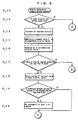
- Step S1 based on the wheel velocity pulse outputted from the wheel velocity sensor 1 for each one second, the angular velocity of rotation Fi of each tyre Wi is computed (Step S1). however, since each tyre Wi is manufactured with including dispersion within the standard (initial difference), the effective rolling radius of the tyres Wi are not necessarily identical to one another even with all at normal inner pressure. For this reason, the angular velocity of rotation Fi of each tyre Wi is different.
- Step S3 based on the above F1i, vehicle velocity V, turning radius R, lateral G, and forward and backward acceleration A are computed (Step S3).
- Step S4 based on the size of the vehicle turning radius R, vehicle velocity V, vehicle lateral direction acceleration G, and forward and backward acceleration A, identification is made as to whether the angular velocity of rotation F1i obtained in the step S2 is rejected or not (Step S4).
- Step S4 when the angular velocity of rotation F1i is not rejected, the judgement value D is computed by the following equation (3) based on the angular velocity of rotation F1i (Step S5).
- D (F 1 +F 4 -F 2 -F 3 )/ ⁇ (F 1 +F 2 +F 3 +F 4 )/2 ⁇
- the computation of the vehicle turning radius R, vehicle velocity V, vehicle lateral direction acceleration G, and forward and backward acceleration A in the above Step S5 is carried out by using the angular velocity of rotation F1i to which the correction of the initial difference is made.
- the effective rolling radius of. the tyre Wi fluctuates by not only the initial difference but also the vehicle turning radius R, vehicle velocity V, vehicle lateral direction acceleration G, and forward and backward acceleration A. Accordingly, to the judgement value D obtained in the step S5, there are acted the effects of the fluctuation factors including the vehicle turning radius R, vehicle velocity V, vehicle lateral direction acceleration G, and forward and backward acceleration A.
- ⁇ 1 and ⁇ 2 are coefficients. These coefficients ⁇ 1 and ⁇ 2 are those previously obtainable by a procedure in which the vehicle running test is carried out when it is known certainly that each tyre Wi is normal, and based on the vehicle turning radius R, vehicle velocity V, vehicle lateral direction acceleration G, and forward and backward acceleration A calculated at that time.
- the coefficients ⁇ 1 and ⁇ 2 are previously memorised in, for example, the ROM 2c of the control unit 2.
- Step S7 judgement is made whether the air pressure is loweror not by the following equation (5) (Step S7).
- Step S9 if the judgement value D' satisfies the equation (5), then it is judged that the air pressure has decreased. If the same judgements are made for a plurality of times continuously, then an alarm is issued (Step S9). On the contrary, if the judgement value D' does not satisfy the equation (5), then it is judged that the air pressure has not decreased, or if the same judgements are made for only one or two times, then an alarm is not given (Step S8).
- Step S10 a preparation process for generation of an alarm (hereinafter referred to as velocity regression pressure decrease judgement method) is carried out.
- V TH a predetermined threshold value
- a TH 0 G
- the vehicle velocity V is less than the predetermined threshold value V TH and the forward and deceleration A is less than the threshold value A TH , no problem as described above occurs, so that it is unnecessary to carry out the velocity regression pressure decrease judgement method as described hereinafter. Also, in the case of judgement that the vehicle velocity V is less than the threshold value V TH or the forward and deceleration A is less than the threshold value A TH , no velocity regression pressure decrease judgement method is applied. In such cases, without undergoing the steps S12-S25, the sequence returns to the step S1. On the other hand, when the vehicle velocity V is judged to be higher than the threshold value V TH and the acceleration A is higher than the threshold value A TH , then the velocity regression pressure decrease judgement method of S12-S26 as described below is applied.
- the process begins by classifying the velocity V by regions (Step S12).
- Step S12 assuming for example to the classification of the velocity into the regions of 1 to 14 for 10 km/h from 120 km/h, if the velocity V at present is for example 135 km/h, since the velocity in the range of 120 km/h is in region of 1, the data for 135 km/h comes in to the 130 km/h range, so that it is included in region 2.
- the number of regions is determined by the allowable velocity of vehicle.
- Step S13, S14 the current judgement value D' and velocity V are added to the velocity range allocated by the step S12 (Steps S13, S14).
- steps S13 and S14 as will be understood from the flow chart of Figure 3, the velocity regression pressure loss judgement processing is carried out every second, and when the vehicle is judged to be running at a high velocity and to be in the driven state steps S12 - S26 as shown in Figure 4 are carried out. Accordingly, when the vehicle is judged to be running at a high velocity and in driven state, the processing is carried out such as to put the velocity V and the judgement value D' every second into the corresponding region, and to add the value to the value added up so far.
- Step S15 counting up is made to count the number of data in the currently corresponding velocity region.
- the velocity V and the judgement value D' for every second usable for the velocity regression pressure loss judgement processing for the vehicle at a high velocity and in the driven state, are added up for the divided region, and the number of the data in the region is counted.
- Step 17 examination is made to see to whether there is any velocity region having less that six data, (Step 17). If there is, each average of the judgement value D' and the velocity V added so far in said region is obtained (Step S18) to count up how many regions containing not less than 6 data have been formed (Step S19). If there is no region, no special operation is made.
- Step 24 if the judgement value CrosP satisfies the equation (6), then it is judged that the air pressure has decreased, and an alarm is issued (Step 24). On the other hand, if the judgement value CrosP does not satisfy the equation (6), then it is judged that the air pressure has not decreased, and an alarm is cancelled (Step S26). When the various conditions are met and a judgement of an alarm has been given, the variables in all velocity regions are cleared.
- Step S 1 7 the judgement value D' obtained in the step S 1 6
- the alarm flag is set, while if not, the alarm flag is cleared.
- Step S 1 8 the velocity regression pressure loss judgement is carried out.
- an alarm flag is set, while if not, the alarm flag is cleared. Further, processing is made so that, if the alarm flag is set, then the alarm lamp is put on, and if not, the alarm lamp is put off (Steps S 1 9-S 1 11).
- the present embodiment it is designed to obtain the judgement value D' at a low velocity by the secondary function, and even when the vehicle is running at a relatively high velocity, only in the case of the vehicle being driven, a preparation process for generation of alarm is carried out again.
- V TH the predetermined threshold value
- a TH 0G or -0.03G
- Step S 1 14 the process begins with the practice of classifying the velocity V at present by regions.
- Step S 1 14 concretely, assuming for example to classify the velocity into the regions of 1 to 14 by 5 km/h from 85 km/h to 155 km/h, if the velocity V at present is for example 100 km/h, since the velocity in the range of 85 km/h is in the region of 1, the data of 100 km/h comes under the 100 km/h range, so that it is to be included in the region of 4.
- the number of divisional regions is determined by the maximum velocity of vehicle.
- Step S 1 15 the current judgement value D' and velocity V are added to the velocity region allocated by the step S 1 14 (Step S 1 15).
- the velocity regression pressure decrease judgement processing is carried out every second, and when the vehicle is judged to be running at a high velocity and in driven state from the velocity V and the acceleration A, the steps S 1 14- S 1 25 as shown in Figures 9 and 10 are carried out. Accordingly, when the vehicle is judged to be running at a high velocity and in driven state, the processing is carried out such as to put the velocity V and the judgement value D' at every second into the corresponding region, and to add the value to the values added up so far.
- Step S 1 16 To summarise the steps S 1 14- S 1 16 here, the velocity V and the judgement value D' at every second, which are usable for the velocity regression pressure decrease judgement processing, are added up to the divided region, and the number of the counters in the corresponding region is increased by one.
- Step S 1 17 examination is made as to whether there are in all regions the predetermined number (e.g. four regions) of velocity regions having not less than the predetermined number (.e.g. 15) of data or not. If there is, an average of the judgement value D' added so far in the region and mean value of each velocity region are obtained (Step S 1 18).
- the average D' in all regions is set to be zero (Step S 1 19- S 1 20).
- the alarm judgement value to be ultimately obtained should be made zero, so that no alarm is detected.
- the steps S 1 19-S 1 20 are not to be limited to them.
- operation is made from the region to be used for the least squares method or from the relation of the average D' in the steps S 1 19- S 1 20, there is an apprehension to produce erroneous judgement.
- the regression data are gathered in the four velocity ranges which are considerably separated from the medium and low velocities and the judgement value of the data show decrease against the increase in velocities, in the case where the difference c between the maximum value and the minimum value is of a dispersion degree within a normal inner pressure of, for example, not more than 0.03, there is a possibility for erroneous judgement to be led out if a regression curve is obtained on the basis of such value.
- the value d in Figure 11 is an alarm judgement threshold value.
- the average D' can be set to zero.
- the threshold value of the alarm judgement can be changed (e.g. to provide a variant for duplication).
- the average D' of the lower limit velocity might be weighted (e.g. to make two part equivalents).
- the judgement value D' at a low velocity is obtained by the least squares method, based on the intermediate velocity V averaged in the respective regions and the average D' (Step S 1 21).
- Step S 1 22- S 1 25 judgement is made as to whether the air pressure is decreased or not (Step S 1 22- S 1 25) by the equation (8).
- Step S 1 23 if the judgement value CrosP satisfies the equation (8), then it is judged that the air pressure has decreased, and an alarm flag is set. On the other hand, if the judgement value CrosP does not satisfy the equation (8), then it is judged that the air pressure has not decreased, and the alarm flag is cleared (Step S 1 24). When various conditions are met and a judgement if alarm is given, the variables in all velocity regions are cleared (Step S 1 25).
- a plurality of judging means suited respectively to the vehicle running conditions. Accordingly, the judgement according to the vehicle running condition can be realised in any judging means. Consequently, it is possible to detect accurately whether or not tyre air pressure decreases regardless of the vehicle running condition, and as a result it is possible to prevent erroneous issuance or non-issuance of alarm. Since this invention thus serves to improve the driver's reliability on the alarm, improvement of traffic safety can be expected.
- judging means for high velocity such as to carry out judgement if the conditions such that, after the detection of the angular velocity of rotation, the vehicle velocity is not less than the threshold value and yet the vehicle is in driven state are satisfied. Therefore, regardless of the running velocity level of the vehicle, accurate detection can be made as to whether the air pressure of the tyre has decreased or not. Accordingly, erroneous issuance or non-issuance of alarm can be prevented.
Landscapes
- Engineering & Computer Science (AREA)
- Mechanical Engineering (AREA)
- Measuring Fluid Pressure (AREA)
Claims (5)
- Procédé de détection de la réduction de pression pneumatique d'un pneumatique dans un véhicule en déplacement possédant quatre roues munies de pneumatiques (W1,... W4), comprenant les étapes suivantes :dans une première étape, la détection et le calcul de chaque vitesse angulaire (F1, ... F4) de rotation des quatre roues munies de pneumatiques (pas S1),la correction de la vitesse angulaire d'au moins une roue pour la compensation de la différence initiale entre les rayons de roulement des pneumatiques due aux différences de fabrication, et le calcul de vitesses angulaires corrigées (F11,... F14) (pas S2),le calcul d'une valeur de jugement (D) d'après les vitesses angulaires corrigées (F11,... F14) (pas S5),le jugement, dans une étape de jugement de faible vitesse, du fait que la pression pneumatique du pneumatique est réduite ou non d'après la valeur de jugement (D) (pas S7),l'émission d'une alarme lorsqu'il est déterminé que la pression pneumatique est abaissée (pas S8 et S9),la détection de la vitesse (V) du véhicule (pas S10, S11),la détection du fait que le véhicule se déplace à l'état mené (pas S10, S11),l'exécution des étapes suivantes de jugement de réduction de pression par régression de vitesse pour une vitesse élevée uniquement lorsque la vitesse (V) du véhicule est supérieure à une valeur de seuil (VTH) et simultanément le véhicule est déplacé à l'état mené (pas S11), avec dans le cas contraire retour à la première étape (S1) :la classification de la vitesse du véhicule par régions (pas S12),l'addition de la valeur de jugement (D) à la région correspondante de vitesse (pas S13),l'addition de la vitesse du véhicule (V) à la région de vitesse correspondante (pas S14),lorsque chacune des régions d'un premier nombre de régions de vitesse comporte au moins un second nombre de données (pas S17), l'obtention d'une moyenne des valeurs de jugement (D) et d'une moyenne des données de vitesse (V) ajoutées dans les régions de vitesse (pas S18), avec retour dans le cas contraire à la première étape (pas S1),l'adoption d'une fonction du second ordre (y = ax2 + b) de la valeur de jugement comme variable dépendante (Y) et de la vitesse comme variable indépendante (x) à partir des valeurs de la moyenne des valeurs de jugement (D) et des valeurs de la moyenne des données de vitesse (V) des régions de vitesse par la méthode des moindres carrés (pas S22),l'obtention, à partir de la fonction du second ordre, d'une valeur d'une fonction de jugement de vitesse élevée (crosp) (pas S22),le jugement, dans une étape de jugement de vitesse élevée, du fait que la pression pneumatique du pneumatique est réduite ou non d'après la valeur de la fonction de jugement de vitesse élevée (crosp) (pas S23), etl'émission d'une alarme lorsqu'il est déterminé que la pression pneumatique est réduite (pas S24).
- Procédé selon la revendication 1, caractérisé par l'étape de correction de la première valeur de jugement de pression en fonction d'au moins un paramètre choisi parmi le rayon de virage du véhicule, la vitesse du véhicule, une accélération latérale du véhicule, et l'accélération vers l'avant et vers l'arrière du véhicule.
- Appareil de détection de la réduction d'une pression pneumatique d'un pneumatique, comprenant un dispositif de calcul de vitesse angulaire (2 ; S1) destiné à calculer une vitesse angulaire (F1,...F4) pour chaque roue (W1,... W4) d'un véhicule, un dispositif de correction de vitesse angulaire (2 ; S2) destiné à corriger la vitesse angulaire d'au moins une roue pour compenser les rayons non uniformes de roulement des pneumatiques respectifs dus aux tolérances de fabrication, un premier dispositif de calcul de valeurs de jugement de pression (2 ; S5) destiné à calculer une première valeur de jugement de pression (D) d'après une vitesse angulaire corrigée (F11,... F14) de toutes les roues, un premier dispositif d'activation (2 ; S7-S9) destiné à activer une alarme lorsque la première valeur de jugement de pression (D) est supérieure à une valeur prédéterminée de jugement de pression, un dispositif de détection de vitesse du véhicule (1-2 ; S10-S11) destiné à détecter la vitesse (B) du véhicule, un second dispositif de calcul de valeur de jugement de pression (2 ; S10) destiné à calculer une seconde valeur de jugement de pression (crosp) en fonction d'une vitesse angulaire de toutes les roues lorsque la vitesse (V) et l'accélération (A) du véhicule dépassent une valeur prédéterminée de vitesse du véhicule et une valeur prédéterminée d'accélération du véhicule, dans lequel le second dispositif de calcul d'une valeur de jugement de pression (2 ; S10) comporte en outre un dispositif de mémorisation (2d) destiné à mémoriser plusieurs valeurs de vitesse du véhicule (V) et plusieurs premières valeurs de jugement de pression (D), un dispositif de division (2 ; S12-S14) destiné à diviser les valeurs de vitesse du véhicule (V) en plusieurs régions à des intervalles prédéterminés et à ajouter chaque valeur de vitesse et la première valeur de jugement de pression associée à la région correspondante, un dispositif de calcul de valeur de vitesse moyenne (2 ; S17-S18) destiné à calculer une valeur de vitesse moyenne pour chaque région lorsque chaque région comprend un nombre prédéterminé de valeurs de vitesse de véhicule, et un dispositif de dérivation d'une fonction du second ordre (2, S22) destiné à calculer la seconde valeur de jugement à partir d'une fonction du second ordre (y = ax2 + b) dérivée par la méthode des moindres carrés par mise en oeuvre d'un nombre prédéterminé de valeurs de vitesse moyenne et de premières valeurs associées de jugement de pression, dans lequel l'appareil comporte en outre un second dispositif d'activation d'alarme (2 ; S23-S25) destiné à activer l'alarme lorsque la seconde valeur de jugement de pression dépasse la valeur prédéterminée de jugement de pression.
- Appareil selon la revendication 3, caractérisé par un dispositif de correction de la première valeur de jugement de pression par un paramètre choisi au moins parmi un rayon de virage du véhicule, la vitesse du véhicule, une accélération latérale du véhicule, et au moins une accélération vers l'avant et vers l'arrière du véhicule.
- Procédé de détection d'une réduction de la pression pneumatique d'un pneumatique dans un véhicule mobile ayant quatre roues munies de pneumatiques (W1,... W4), comprenant les étapes suivantes :dans une première étape, la détection et le calcul de chaque vitesse angulaire (F1,...F4) de rotation des quatre roues munies de pneumatiques (pas S11),la correction de la vitesse angulaire d'au moins une roue pour la compensation de la différence initiale de rayon de roulement entre les pneumatiques à cause des différences de fabrication, et le calcul de vitesses angulaires corrigées (F11,... F14) (pas S12),le calcul d'une valeur de jugement (D) qui dépend des vitesses angulaires corrigées (F11,... F14) (pas S15),l'exécution des étapes suivantes de jugement de pression par régression de vitesse à partir d'une vitesse élevée uniquement lorsque la vitesse (V) du véhicule dépasse une valeur de seuil (VTH) et simultanément le véhicule se déplace à un état mené (pas S18, S112, S113), avec dans le cas contraire retour à la première étape,la classification de la vitesse du véhicule en régions (pas S114),l'addition de la valeur de jugement (D) à la région correspondante de vitesse (pas S115),lorsque chaque région d'un premier nombre de régions de vitesse contient au moins un second nombre de données (pas S117), l'obtention d'une moyenne des valeurs de jugement (D) ajoutées dans les régions de vitesse et de la valeur moyenne de chaque région de vitesse (pas S118), avec retour dans le cas contraire à la première étape (pas S11),le jugement du fait que la différence entre la valeur maximale et la valeur minimale de la moyenne (D) est inférieure à la valeur prédéterminée de seuil (pas S119),l'adoption d'une fonction du second ordre (y = ax2 + b) de la valeur de jugement comme variable dépendante (y) et de la vitesse comme variable indépendante (x) à partir des valeurs de la moyenne des valeurs de jugement (D) et de la valeur moyenne de chaque région de vitesse par la méthode des moindres carrés (pas S121),l'obtention, à partir de la fonction du second ordre, d'une valeur de fonction de jugement à faible vitesse (crosp) (pas S121),le jugement du fait que la pression pneumatique du pneumatique est réduite ou non d'après la valeur de fonction de jugement à faible vitesse (crosp) (pas S122), etl'émission d'une alarme lorsqu'il est déterminé que la pression pneumatique est abaissée (pas S19, S111, S123).
Applications Claiming Priority (3)
| Application Number | Priority Date | Filing Date | Title |
|---|---|---|---|
| JP92311/96 | 1996-04-15 | ||
| JP9231196 | 1996-04-15 | ||
| JP9231196 | 1996-04-15 |
Publications (2)
| Publication Number | Publication Date |
|---|---|
| EP0802074A1 EP0802074A1 (fr) | 1997-10-22 |
| EP0802074B1 true EP0802074B1 (fr) | 2003-08-20 |
Family
ID=14050864
Family Applications (1)
| Application Number | Title | Priority Date | Filing Date |
|---|---|---|---|
| EP97302472A Expired - Lifetime EP0802074B1 (fr) | 1996-04-15 | 1997-04-11 | Appareil et procédé concernant la détection d'une baisse de pression dans un pneumatique |
Country Status (4)
| Country | Link |
|---|---|
| US (1) | US5900543A (fr) |
| EP (1) | EP0802074B1 (fr) |
| KR (1) | KR100312875B1 (fr) |
| DE (1) | DE69724176T2 (fr) |
Families Citing this family (17)
| Publication number | Priority date | Publication date | Assignee | Title |
|---|---|---|---|---|
| JP3340961B2 (ja) * | 1997-10-06 | 2002-11-05 | 住友ゴム工業株式会社 | タイヤ空気圧低下警報装置および方法 |
| FR2785574B1 (fr) | 1998-11-10 | 2001-01-12 | Jean Claude Galland | Procedes et dispositifs de detection et de mesure en cours de route du degonflement des pneumatiques |
| EP1194304B1 (fr) * | 1999-06-19 | 2006-07-26 | Continental Teves AG & Co. oHG | Procede et dispositif pour elaborer une table de valeurs de correction, determiner une valeur d'essai et detecter une perte de pression dans un pneu de roue |
| US6822561B2 (en) * | 1999-12-15 | 2004-11-23 | Continental Aktiengesellschaft | Method and device for detecting a drop in pressure in motor vehicle tires |
| US6285280B1 (en) | 2000-06-26 | 2001-09-04 | Robert Bosch Corporation | Method for detecting a deflated tire on a vehicle |
| US8266465B2 (en) | 2000-07-26 | 2012-09-11 | Bridgestone Americas Tire Operation, LLC | System for conserving battery life in a battery operated device |
| US7161476B2 (en) | 2000-07-26 | 2007-01-09 | Bridgestone Firestone North American Tire, Llc | Electronic tire management system |
| JP3641419B2 (ja) * | 2000-09-05 | 2005-04-20 | 住友ゴム工業株式会社 | タイヤ空気圧低下警報装置および方法 |
| US6459369B1 (en) | 2000-11-22 | 2002-10-01 | Robert Bosch Corporation | Tire deflation detection system with feedback component |
| JP3869685B2 (ja) * | 2001-06-20 | 2007-01-17 | 住友ゴム工業株式会社 | 二輪車用空気圧低下検出装置および方法、ならびに二輪車用減圧判定プログラム |
| WO2003006268A1 (fr) * | 2001-07-09 | 2003-01-23 | Continental Teves Ag & Co. Ohg | Systeme et procede de controle de la pression des pneus d'un vehicule automobile |
| DE10144362B4 (de) * | 2001-09-10 | 2005-10-27 | Siemens Ag | Verfahren und System zur Detektion einer Zustandsänderung eines Reifens |
| JP2003267012A (ja) * | 2002-01-09 | 2003-09-25 | Sumitomo Rubber Ind Ltd | タイヤ空気圧低下検出方法および装置、ならびにタイヤ減圧判定のプログラム |
| DE10300330B4 (de) * | 2002-01-09 | 2018-12-06 | Continental Teves Ag & Co. Ohg | Verfahren zur Erkennung eines Reifendruckverlusts |
| US20050109093A1 (en) * | 2003-11-21 | 2005-05-26 | Siemens Vdo Automotive Corporation | System and method for detecting low tire pressure |
| US6945103B1 (en) | 2004-04-26 | 2005-09-20 | Seetron Inc. | Tire status monitoring system |
| JP4637011B2 (ja) * | 2005-12-12 | 2011-02-23 | 住友ゴム工業株式会社 | タイヤ空気圧異常警報方法、装置およびプログラム |
Citations (3)
| Publication number | Priority date | Publication date | Assignee | Title |
|---|---|---|---|---|
| EP0291217A2 (fr) * | 1987-05-13 | 1988-11-17 | Sp Tyres Uk Limited | Méthode de détection du dégonflage d'un pneumatique sur un véhicule |
| EP0441600A2 (fr) * | 1990-02-09 | 1991-08-14 | Sumitomo Rubber Industries Limited | Méthode de détection du dégonflage d'un pneumatique sur un véhicule |
| EP0786362A2 (fr) * | 1996-01-26 | 1997-07-30 | Sumitomo Electric Industries, Ltd. | Méthode et dispositif de détection de perte de pression d'un pneumatique |
Family Cites Families (6)
| Publication number | Priority date | Publication date | Assignee | Title |
|---|---|---|---|---|
| GB9026560D0 (en) * | 1990-12-06 | 1991-01-23 | Sumitomo Rubber Ind | Method of detecting a deflated tyre on a vehicle |
| JP2780887B2 (ja) * | 1992-01-31 | 1998-07-30 | 本田技研工業株式会社 | 車両のタイヤ空気圧判定装置 |
| EP0656268B1 (fr) * | 1992-09-16 | 1998-12-02 | Sumitomo Electric Industries, Ltd. | Appareil et procede concernant la detection d'une baisse de pression dans un pneumatique |
| EP0607690B1 (fr) * | 1992-12-21 | 1997-02-19 | Sumitomo Rubber Industries Limited | Procédé et dispositif de détection d'anomalies de gonflage pour pneumatiques |
| US5578984A (en) * | 1993-11-04 | 1996-11-26 | Sumitomo Electric | Tire air pressure reduction detecting method and apparatus |
| JPH08164720A (ja) * | 1994-12-15 | 1996-06-25 | Sumitomo Electric Ind Ltd | タイヤ空気圧低下検出方法およびタイヤ空気圧低下検出装置 |
-
1997
- 1997-04-10 US US08/838,736 patent/US5900543A/en not_active Expired - Lifetime
- 1997-04-10 KR KR1019970013296A patent/KR100312875B1/ko not_active IP Right Cessation
- 1997-04-11 DE DE69724176T patent/DE69724176T2/de not_active Expired - Lifetime
- 1997-04-11 EP EP97302472A patent/EP0802074B1/fr not_active Expired - Lifetime
Patent Citations (3)
| Publication number | Priority date | Publication date | Assignee | Title |
|---|---|---|---|---|
| EP0291217A2 (fr) * | 1987-05-13 | 1988-11-17 | Sp Tyres Uk Limited | Méthode de détection du dégonflage d'un pneumatique sur un véhicule |
| EP0441600A2 (fr) * | 1990-02-09 | 1991-08-14 | Sumitomo Rubber Industries Limited | Méthode de détection du dégonflage d'un pneumatique sur un véhicule |
| EP0786362A2 (fr) * | 1996-01-26 | 1997-07-30 | Sumitomo Electric Industries, Ltd. | Méthode et dispositif de détection de perte de pression d'un pneumatique |
Also Published As
| Publication number | Publication date |
|---|---|
| KR19980076549A (ko) | 1998-11-16 |
| DE69724176D1 (de) | 2003-09-25 |
| EP0802074A1 (fr) | 1997-10-22 |
| DE69724176T2 (de) | 2004-02-26 |
| US5900543A (en) | 1999-05-04 |
| KR100312875B1 (ko) | 2001-12-12 |
Similar Documents
| Publication | Publication Date | Title |
|---|---|---|
| EP0802074B1 (fr) | Appareil et procédé concernant la détection d'une baisse de pression dans un pneumatique | |
| US5828975A (en) | Method and device for calculating turning radius of vehicle taking load movement thereof into consideration | |
| US5629478A (en) | Method of and device for detecting tire pressure drop based on angular velocity | |
| US5721528A (en) | Low tire warning system | |
| US7205886B2 (en) | Tire pressure monitoring system | |
| US5959202A (en) | Device for determining initial correction factor for correcting rotational velocity of tire | |
| EP0832766B1 (fr) | Appareil de détection de la pression de pneumatiques | |
| EP0863028B1 (fr) | Procédé permettant de détecter un pneumatique dégonflé sur un véhicule | |
| US5936519A (en) | Method of and device for detecting tire pressure drop | |
| JP3095836B2 (ja) | タイヤデフレーションの検出方法 | |
| US5524482A (en) | Detecting a deflated vehicle tire by comparing angular velocity data of all wheels, a data table, and the directly-measured pressure of a single tire | |
| EP0724974B1 (fr) | Dispositif d'alarme de perte de pression dans un pneumatique | |
| JP4823642B2 (ja) | Gps情報を用いたタイヤ内圧低下警報方法および装置、ならびにタイヤ内圧低下警報プログラム | |
| US20020157461A1 (en) | Method and system for monitoring tire pressure in vehicles equipped with anti-lock braking systems | |
| US5442331A (en) | Method and device for detecting a deflated tire by comparing angular velocity and forward/backward speed data with a data table | |
| KR100288604B1 (ko) | 차량의감압된타이어검출방법 | |
| GB2326007A (en) | Vehicle tyre pressure monitoring system | |
| US5907097A (en) | Method of and device for detecting tire pressure drop | |
| US6504475B2 (en) | Apparatus and method for alarming decrease in tire air-pressure | |
| EP0787606B1 (fr) | Procédé permettant de détecter un pneumatique dégonflé sur un véhicule | |
| JP3129671B2 (ja) | タイヤの空気圧低下検出方法およびその装置 | |
| JP3167278B2 (ja) | タイヤ空気圧低下検出方法および装置 | |
| JPH0966714A (ja) | タイヤ空気圧低下検出方法および装置 | |
| CN1978228A (zh) | 轮胎气压异常报警装置、方法和程序 |
Legal Events
| Date | Code | Title | Description |
|---|---|---|---|
| PUAI | Public reference made under article 153(3) epc to a published international application that has entered the european phase |
Free format text: ORIGINAL CODE: 0009012 |
|
| AK | Designated contracting states |
Kind code of ref document: A1 Designated state(s): DE FR GB IT SE |
|
| 17P | Request for examination filed |
Effective date: 19971106 |
|
| 17Q | First examination report despatched |
Effective date: 20000222 |
|
| GRAH | Despatch of communication of intention to grant a patent |
Free format text: ORIGINAL CODE: EPIDOS IGRA |
|
| GRAS | Grant fee paid |
Free format text: ORIGINAL CODE: EPIDOSNIGR3 |
|
| GRAA | (expected) grant |
Free format text: ORIGINAL CODE: 0009210 |
|
| AK | Designated contracting states |
Designated state(s): DE FR GB IT SE |
|
| REG | Reference to a national code |
Ref country code: GB Ref legal event code: FG4D |
|
| REF | Corresponds to: |
Ref document number: 69724176 Country of ref document: DE Date of ref document: 20030925 Kind code of ref document: P |
|
| REG | Reference to a national code |
Ref country code: SE Ref legal event code: TRGR |
|
| ET | Fr: translation filed | ||
| PLBE | No opposition filed within time limit |
Free format text: ORIGINAL CODE: 0009261 |
|
| STAA | Information on the status of an ep patent application or granted ep patent |
Free format text: STATUS: NO OPPOSITION FILED WITHIN TIME LIMIT |
|
| 26N | No opposition filed |
Effective date: 20040524 |
|
| REG | Reference to a national code |
Ref country code: FR Ref legal event code: PLFP Year of fee payment: 20 |
|
| PGFP | Annual fee paid to national office [announced via postgrant information from national office to epo] |
Ref country code: FR Payment date: 20160309 Year of fee payment: 20 |
|
| PGFP | Annual fee paid to national office [announced via postgrant information from national office to epo] |
Ref country code: GB Payment date: 20160406 Year of fee payment: 20 Ref country code: DE Payment date: 20160405 Year of fee payment: 20 |
|
| PGFP | Annual fee paid to national office [announced via postgrant information from national office to epo] |
Ref country code: SE Payment date: 20160412 Year of fee payment: 20 Ref country code: IT Payment date: 20160418 Year of fee payment: 20 |
|
| REG | Reference to a national code |
Ref country code: DE Ref legal event code: R071 Ref document number: 69724176 Country of ref document: DE |
|
| REG | Reference to a national code |
Ref country code: GB Ref legal event code: PE20 Expiry date: 20170410 |
|
| PG25 | Lapsed in a contracting state [announced via postgrant information from national office to epo] |
Ref country code: GB Free format text: LAPSE BECAUSE OF EXPIRATION OF PROTECTION Effective date: 20170410 |