EP0802011A2 - Procédé pour relier deux feuilles métalliques - Google Patents
Procédé pour relier deux feuilles métalliques Download PDFInfo
- Publication number
- EP0802011A2 EP0802011A2 EP97102924A EP97102924A EP0802011A2 EP 0802011 A2 EP0802011 A2 EP 0802011A2 EP 97102924 A EP97102924 A EP 97102924A EP 97102924 A EP97102924 A EP 97102924A EP 0802011 A2 EP0802011 A2 EP 0802011A2
- Authority
- EP
- European Patent Office
- Prior art keywords
- metal
- foils
- welding
- metal foils
- metal wire
- Prior art date
- Legal status (The legal status is an assumption and is not a legal conclusion. Google has not performed a legal analysis and makes no representation as to the accuracy of the status listed.)
- Withdrawn
Links
Images

Classifications
-
- B—PERFORMING OPERATIONS; TRANSPORTING
- B23—MACHINE TOOLS; METAL-WORKING NOT OTHERWISE PROVIDED FOR
- B23K—SOLDERING OR UNSOLDERING; WELDING; CLADDING OR PLATING BY SOLDERING OR WELDING; CUTTING BY APPLYING HEAT LOCALLY, e.g. FLAME CUTTING; WORKING BY LASER BEAM
- B23K11/00—Resistance welding; Severing by resistance heating
- B23K11/06—Resistance welding; Severing by resistance heating using roller electrodes
- B23K11/061—Resistance welding; Severing by resistance heating using roller electrodes for welding rectilinear seams
-
- B—PERFORMING OPERATIONS; TRANSPORTING
- B23—MACHINE TOOLS; METAL-WORKING NOT OTHERWISE PROVIDED FOR
- B23K—SOLDERING OR UNSOLDERING; WELDING; CLADDING OR PLATING BY SOLDERING OR WELDING; CUTTING BY APPLYING HEAT LOCALLY, e.g. FLAME CUTTING; WORKING BY LASER BEAM
- B23K11/00—Resistance welding; Severing by resistance heating
- B23K11/30—Features relating to electrodes
- B23K11/309—Wire electrodes
-
- B—PERFORMING OPERATIONS; TRANSPORTING
- B23—MACHINE TOOLS; METAL-WORKING NOT OTHERWISE PROVIDED FOR
- B23K—SOLDERING OR UNSOLDERING; WELDING; CLADDING OR PLATING BY SOLDERING OR WELDING; CUTTING BY APPLYING HEAT LOCALLY, e.g. FLAME CUTTING; WORKING BY LASER BEAM
- B23K2101/00—Articles made by soldering, welding or cutting
- B23K2101/18—Sheet panels
Definitions
- the invention relates to a method for connecting two thin sheets or metal foils which are at least partially, e.g. lying in the edge areas, one on top of the other, and a device for this.
- Thin sheets and foils are flat, self-supporting and flexible structures with thicknesses between 2 ⁇ m and 0.2 mm, in particular between 20 ⁇ m and 0.1 mm, which are made, for example, of rustproof austenitic or ferritic materials consist. This small thickness makes it difficult to connect two metal foils together. This applies especially if the connection is to be made via a weld seam.
- the resistance roller seam welding process is known for connecting two metal foils which are placed one above the other.
- the metal foils to be connected are passed between the two rollers, the rollers being supplied with current, preferably with alternating current.
- the flow of current through the two foils between the two welding rollers causes the contact area of the two metal foils to melt, a weld seam being formed between the two metal foils which connects the two metal foils to one another.
- This weld seam usually consists of individual successive welding lenses, the size of which perfect weld seam is in a certain ratio to the thickness of the metal foil and the seam width.
- the present invention is based on the object of developing a method for connecting metal foils and a corresponding device by means of which a weld seam can be produced in a qualitatively flawless manner, the speed of producing the connection being considerably increased.
- the object is achieved in that an intermediate wire electrode is used for welding.
- the wire electrode is guided around the welding rollers in such a way that it lies between the metal foil to be welded and the welding roller during the welding process. This means that there is no longer any direct contact between the film and the welding roll.
- Roll seam welding with a wire electrode is generally known; it is used in can welding, where can frames in the thin sheet area are to be manufactured with sheet thicknesses between 0.12 and 0.5 mm.
- Tin plates have special properties which are different from the metal foils to be joined according to the invention: tin plates are provided with a metallic coating, in the case of tin as the coating tinplate is present. Tin now has a lower melting point than the actual sheet to be joined, so that it liquefies before the welding temperature is reached. Tin is therefore inevitably deposited on the roll surfaces of the welding rolls. This contamination of the roller surfaces change the welding conditions (among other things, transition resistance and contact area) to an uncontrollable extent.
- a metal foil of the type described does not on the one hand have an additional metallic coating with a lower melting point than the foil material or only has a spontaneously formed coating, which by Oxidation of the film material naturally occurs and its thickness can be influenced by machining processes.
- a metal foil of the type described can only be coated with a corrosion protection layer (for example chromium oxide) which has a higher melting point than the material of the actual metal foil.
- Electrolyte copper is preferably used as the material for the wire intermediate electrodes, which has a significantly higher electrical and thermal conductivity than that in the roll seam welding process without wire intermediate electrode used welding roll materials.
- the conductivity of electrolytic copper is approximately twice that of the welding roller material made of an alloy of copper, cobalt and beryllium, which is commonly used for welding stainless steels. The better thermal conductivity results in a much better heat dissipation from the sheet surface. It seems that this reduces the risk of the films burning through.
- the much lower yield strength or hardness of electrolytic copper which is, for example, only about a third of the value for CuCoBe alloys, causes the surface of the wire intermediate electrode to be deformed by the welding force and thus a much better adaptation of the current contact surface to the surface structure of the metal foil and thereby a reduction in the contact resistance between the electrode contact surface and the sheet surface and a more uniform current density over a better-defined area in the foils, which according to the applicant's first investigations helps to reduce the heating of the foil surface, so that the burning through of the foil occurs with a delay.
- the welding speed as such is limited by the welding frequency, which determines the distance between the overlapping welding lenses.
- Another factor, as mentioned, is the cooling of the film surfaces, which slows down the burning of the welding lenses to the outside. Since the cooling of the surface can be significantly improved by the wire intermediate electrodes used according to the invention due to the geometrical relationships prevailing in foils, it is possible to increase the welding frequency in order to achieve higher welding speeds. For example, with welding frequencies of 300-400 Hz welding speeds of 15-20 m / min achieved.
- the effectiveness of the method is preferably increased further in that the metal wire is micro-profiled on the film before being rolled off. For example, this can be done with a simple sandpaper, causing the wire to be longitudinally grooved be molded. These longitudinal grooves probably have the advantage that a larger surface is available for contact with the metal foil, which in turn improves the thermal conductivity but also the current conductivity.
- the resistance-increasing oxide layer acts upon the welding process when a pre-existing night is welded on by a further crossing seam in such a way that it is disrupted and the crossing point burns through.
- Metal foils of this type which are formed into a metal shell by connecting their edge regions on all sides, can be used, for example, to produce an insulating element which is to be used for the lining of refrigerators.
- a refrigerator is still lined with insulating material by inserting styrofoam or by foaming with polyurethane.
- the latter in particular is not desirable for environmental reasons. That is why glass fiber plates are increasingly used today, which are in a metal shell, which are hermetically sealed by welding and subsequently evacuated. They have an improved insulation effect with a smaller thickness, so that more space is available for the actual refrigerator or the cooling room.
- the vacuum of these insulating elements must be maintained for at least 10 years.
- insulating elements of this type can be produced in a cost-effective manner, the weld seam in particular being absolutely tight, that is to say also vacuum-tight.
- a corresponding device for connecting two metal foils which are at least partially, e.g. in edge areas, lying one on top of the other, has two metal wires, which are each guided around a welding roller and between which the two metal foils are welded, the metal wires rolling over the metal foils.
- a device for micro-profiling the metal wire should preferably be connected upstream of at least one roll, this device being able to consist of an abrasive paper for the sake of simplicity.
- an insulating element 1 for use in refrigerator insulation consists of a glass fiber plate 2 which is surrounded by a metal shell 3.
- This metal shell 3 consists of a cover film 4 and a base film 5.
- cover sheet 4 and base sheet 5 lie one on top of the other and are connected there by corresponding weld seams 6, which are only indicated by dashed lines in FIG. 2.
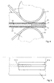
- the cover film 4 and the base film 5 of the insulating element 1 are connected in a device which is only partially indicated in FIG. 3.
- a roller 9 or 10 is arranged on an upper and a lower support arm 7 or 8, which is at least partially wrapped in a metal wire 11 or 12. After the roller 9 or 10, the metal wire 11 or 12 is guided over a further guide roller 13 or 14.
- the insulating element 1 is passed between the rollers 9 and 10, the metal wire 11 or 12 being rolled from one side onto the cover film 4 or the base film 5.
- Metal wire 11 and 12 are drawn off in the directions x 1 and x 2 .
- a device 15 or 16 for micro-profiling the metal wire 11 or 12 is assigned to the metal wire 11 or 12.
- the device 15 or 16 for profiling the metal wire 11 or 12 is an abrasive paper 18 with which a stamp surface 17 of the device 15 or 16 is covered.
- the device 15 or 16 for micro-profiling the surface of the metal wire 11 or 12 is arranged such that the micro-profiled surface of the metal wire rolls on the respective cover film 4 or base film 5.
- the insulating element 1 is evacuated by one not closer shown opening in the cover sheet 4, which is then closed with a seal 19.
- cover sheet 4 and base sheet 5 have an oxide layer 20 or 21, which consists of a compound which has a higher melting point than the actual film 4 or 5.
- This weld seam 22 consists of individual welding lenses 23, which result from the passage of the insulating element 1 through a gap 24 between the metal wires and the action of the metal wires 11 and 12 with alternating current.
Landscapes
- Engineering & Computer Science (AREA)
- Mechanical Engineering (AREA)
- Resistance Welding (AREA)
- Pressure Welding/Diffusion-Bonding (AREA)
- Finish Polishing, Edge Sharpening, And Grinding By Specific Grinding Devices (AREA)
- Non-Insulated Conductors (AREA)
Applications Claiming Priority (2)
| Application Number | Priority Date | Filing Date | Title |
|---|---|---|---|
| CH99596 | 1996-04-19 | ||
| CH995/96 | 1996-04-19 |
Publications (2)
| Publication Number | Publication Date |
|---|---|
| EP0802011A2 true EP0802011A2 (fr) | 1997-10-22 |
| EP0802011A3 EP0802011A3 (fr) | 1998-02-04 |
Family
ID=4200000
Family Applications (1)
| Application Number | Title | Priority Date | Filing Date |
|---|---|---|---|
| EP97102924A Withdrawn EP0802011A3 (fr) | 1996-04-19 | 1997-02-22 | Procédé pour relier deux feuilles métalliques |
Country Status (5)
| Country | Link |
|---|---|
| US (1) | US6011236A (fr) |
| EP (1) | EP0802011A3 (fr) |
| JP (1) | JPH1029070A (fr) |
| KR (1) | KR970069222A (fr) |
| CA (1) | CA2199292A1 (fr) |
Families Citing this family (3)
| Publication number | Priority date | Publication date | Assignee | Title |
|---|---|---|---|---|
| DE10306235B4 (de) * | 2003-02-14 | 2005-02-03 | Daimlerchrysler Ag | Verfahren und Anordnung zum Widerstandsnahtschweißen einer Folie und mindestens eines Folienträgers eines Brennstoffzellensystems |
| JP6378471B2 (ja) * | 2013-07-18 | 2018-08-22 | 日新製鋼株式会社 | 真空断熱パネル |
| JP6143593B2 (ja) * | 2013-07-18 | 2017-06-07 | 日新製鋼株式会社 | 真空断熱パネル |
Citations (1)
| Publication number | Priority date | Publication date | Assignee | Title |
|---|---|---|---|---|
| US4795875A (en) * | 1985-07-01 | 1989-01-03 | Elpatronic Ag | Contact wire for a roller seam welding machine |
Family Cites Families (10)
| Publication number | Priority date | Publication date | Assignee | Title |
|---|---|---|---|---|
| US3654422A (en) * | 1966-07-26 | 1972-04-04 | Continental Can Co | Square wave resistance welding |
| CH595177A5 (en) * | 1976-11-09 | 1978-01-31 | Fael Sa | Ribbed copper electrode strip |
| JPS561281A (en) * | 1979-06-19 | 1981-01-08 | Toyo Seikan Kaisha Ltd | Method and device of welding treatment of can barrel |
| JPS5647281A (en) * | 1979-09-26 | 1981-04-28 | Toyo Seikan Kaisha Ltd | Method and device for producing welded metal can barrel |
| JPS5756173A (en) * | 1980-09-19 | 1982-04-03 | Daiwa Can Co Ltd | Electric resistance seaming and welding method of lateral joint of hollow cylindrical body |
| JPS59183987A (ja) * | 1983-04-04 | 1984-10-19 | Kawasaki Heavy Ind Ltd | スポツト溶接における圧痕周辺部の変色防止方法 |
| JPS59229290A (ja) * | 1983-06-10 | 1984-12-22 | Nippon Kokan Kk <Nkk> | 電気抵抗シ−ム溶接法 |
| KR890002769B1 (ko) * | 1983-09-09 | 1989-07-28 | 도오요오 세이깐 가부시기가이샤 | 용접관동체와 그 제조방법 |
| JPS61206576A (ja) * | 1985-03-11 | 1986-09-12 | Nepiyuu Giken:Kk | 金属板等から成る缶胴のラツプ継手の溶接方法 |
| US5389761A (en) * | 1993-09-17 | 1995-02-14 | General Motors Corporation | Method and apparatus for cleaning metal pieces prior to resistive seam welding or laser lap seam welding |
-
1997
- 1997-02-22 EP EP97102924A patent/EP0802011A3/fr not_active Withdrawn
- 1997-03-04 US US08/811,547 patent/US6011236A/en not_active Expired - Fee Related
- 1997-03-05 CA CA002199292A patent/CA2199292A1/fr not_active Abandoned
- 1997-04-11 KR KR1019970013460A patent/KR970069222A/ko not_active Abandoned
- 1997-04-18 JP JP9101148A patent/JPH1029070A/ja active Pending
Patent Citations (1)
| Publication number | Priority date | Publication date | Assignee | Title |
|---|---|---|---|---|
| US4795875A (en) * | 1985-07-01 | 1989-01-03 | Elpatronic Ag | Contact wire for a roller seam welding machine |
Also Published As
| Publication number | Publication date |
|---|---|
| US6011236A (en) | 2000-01-04 |
| EP0802011A3 (fr) | 1998-02-04 |
| CA2199292A1 (fr) | 1997-10-19 |
| KR970069222A (ko) | 1997-11-07 |
| JPH1029070A (ja) | 1998-02-03 |
Similar Documents
| Publication | Publication Date | Title |
|---|---|---|
| EP0189806B1 (fr) | Méthode pour aboucher en particulier des tôles d'acier ou des feuillards d'acier aptes à l'emboutissage profond et galvanisés au moins d'un côté | |
| DE69531975T2 (de) | Widerstandsbuckelschweissverfahren | |
| DE1527875C3 (de) | Einrichtung zum Ummanteln eines zylindrischen Kerns aus Aluminium mit mindestens einem Metallummantelungsstreifen aus Kupfer | |
| EP0805733A1 (fr) | Procede pour l'assemblage de bandes assiste par laser | |
| DE69732292T2 (de) | Verfahren und vorrichtung zur herstellung von mit thermoplastischem harz beschichtetem metallischem blech | |
| EP0004063B1 (fr) | Procédé de fabrication de tôles plaquées | |
| DE2812415A1 (de) | Verfahren zur herstellung verschweisster blechprofile sowie vorrichtung zur durchfuehrung dieses verfahrens | |
| DE3506011A1 (de) | Verfahren zum herstellen einer mehrschichtigen elekrisch beheizbaren sichtscheibe aus kunststoff | |
| DE1905770C3 (de) | Vorrichtung zum Auftragschweißen auf metallische Werkstücke unter Verwendung eines Gleichstromlichtbogens | |
| EP0628399B1 (fr) | Procédé pour la fabrication d'un corps creux tubulaire | |
| DE3626470A1 (de) | Verfahren zum herstellen einer titanplattierten stahlplatte durch heisswalzen | |
| EP0802011A2 (fr) | Procédé pour relier deux feuilles métalliques | |
| DE1910743B2 (de) | Vorrichtung zum kontinuierlichen verbinden einer kunststoffolie mit einem traeger | |
| EP0140834B1 (fr) | Procédé pour la production de bandes plaquées | |
| DE69419501T2 (de) | Widerstandsschweissverfahren für stahl- und aluminium-metallplatten und widerstandsschweissmaterial | |
| DE19606981C2 (de) | Verfahren zur Herstellung von Leichtbaubändern oder Leichtbaublechen | |
| DE4022238C2 (fr) | ||
| DE3630625C2 (fr) | ||
| DE3722931C1 (de) | Elektrodendraht fuer eine Rollennahtschweissmaschine | |
| EP0166149A1 (fr) | Molette électrode pour le soudage en ligne par résistance électrique | |
| EP0145803A1 (fr) | Procédé pour fabriquer des bandes métalliques plaquées à chaud | |
| DE2919365C2 (de) | Vorrichtung zum Widerstands-RoUennahtschweißen | |
| DE3816541C1 (en) | Process for producing laminated metal composites, and use thereof | |
| DE3842865A1 (de) | Verfahren zur herstellung eines laengsnahtrohres | |
| DE8103868U1 (de) | Vorrichtung zur kontinuierlichen Herstellung von endlosen verformbaren Rohren aus einem Laminatfolienband |
Legal Events
| Date | Code | Title | Description |
|---|---|---|---|
| PUAI | Public reference made under article 153(3) epc to a published international application that has entered the european phase |
Free format text: ORIGINAL CODE: 0009012 |
|
| AK | Designated contracting states |
Kind code of ref document: A2 Designated state(s): BE CH DE ES FR GB IT LI NL PT |
|
| PUAL | Search report despatched |
Free format text: ORIGINAL CODE: 0009013 |
|
| AK | Designated contracting states |
Kind code of ref document: A3 Designated state(s): BE CH DE ES FR GB IT LI NL PT |
|
| 17P | Request for examination filed |
Effective date: 19980804 |
|
| RAP3 | Party data changed (applicant data changed or rights of an application transferred) |
Owner name: ELPATRONIC AG |
|
| 17Q | First examination report despatched |
Effective date: 19990930 |
|
| GRAP | Despatch of communication of intention to grant a patent |
Free format text: ORIGINAL CODE: EPIDOSNIGR1 |
|
| RTI1 | Title (correction) |
Free format text: METHOD AND APPARATUS FOR JOINING TWO METAL FOILS |
|
| RTI1 | Title (correction) |
Free format text: METHOD AND APPARATUS FOR JOINING TWO METAL FOILS |
|
| GRAS | Grant fee paid |
Free format text: ORIGINAL CODE: EPIDOSNIGR3 |
|
| STAA | Information on the status of an ep patent application or granted ep patent |
Free format text: STATUS: THE APPLICATION IS DEEMED TO BE WITHDRAWN |
|
| 18D | Application deemed to be withdrawn |
Effective date: 20031211 |