EP0802011A2 - Method for joining two metal foils - Google Patents
Method for joining two metal foils Download PDFInfo
- Publication number
- EP0802011A2 EP0802011A2 EP97102924A EP97102924A EP0802011A2 EP 0802011 A2 EP0802011 A2 EP 0802011A2 EP 97102924 A EP97102924 A EP 97102924A EP 97102924 A EP97102924 A EP 97102924A EP 0802011 A2 EP0802011 A2 EP 0802011A2
- Authority
- EP
- European Patent Office
- Prior art keywords
- metal
- foils
- welding
- metal foils
- metal wire
- Prior art date
- Legal status (The legal status is an assumption and is not a legal conclusion. Google has not performed a legal analysis and makes no representation as to the accuracy of the status listed.)
- Withdrawn
Links
Images

Classifications
-
- B—PERFORMING OPERATIONS; TRANSPORTING
- B23—MACHINE TOOLS; METAL-WORKING NOT OTHERWISE PROVIDED FOR
- B23K—SOLDERING OR UNSOLDERING; WELDING; CLADDING OR PLATING BY SOLDERING OR WELDING; CUTTING BY APPLYING HEAT LOCALLY, e.g. FLAME CUTTING; WORKING BY LASER BEAM
- B23K11/00—Resistance welding; Severing by resistance heating
- B23K11/06—Resistance welding; Severing by resistance heating using roller electrodes
- B23K11/061—Resistance welding; Severing by resistance heating using roller electrodes for welding rectilinear seams
-
- B—PERFORMING OPERATIONS; TRANSPORTING
- B23—MACHINE TOOLS; METAL-WORKING NOT OTHERWISE PROVIDED FOR
- B23K—SOLDERING OR UNSOLDERING; WELDING; CLADDING OR PLATING BY SOLDERING OR WELDING; CUTTING BY APPLYING HEAT LOCALLY, e.g. FLAME CUTTING; WORKING BY LASER BEAM
- B23K11/00—Resistance welding; Severing by resistance heating
- B23K11/30—Features relating to electrodes
- B23K11/309—Wire electrodes
-
- B—PERFORMING OPERATIONS; TRANSPORTING
- B23—MACHINE TOOLS; METAL-WORKING NOT OTHERWISE PROVIDED FOR
- B23K—SOLDERING OR UNSOLDERING; WELDING; CLADDING OR PLATING BY SOLDERING OR WELDING; CUTTING BY APPLYING HEAT LOCALLY, e.g. FLAME CUTTING; WORKING BY LASER BEAM
- B23K2101/00—Articles made by soldering, welding or cutting
- B23K2101/18—Sheet panels
Definitions
- the invention relates to a method for connecting two thin sheets or metal foils which are at least partially, e.g. lying in the edge areas, one on top of the other, and a device for this.
- Thin sheets and foils are flat, self-supporting and flexible structures with thicknesses between 2 ⁇ m and 0.2 mm, in particular between 20 ⁇ m and 0.1 mm, which are made, for example, of rustproof austenitic or ferritic materials consist. This small thickness makes it difficult to connect two metal foils together. This applies especially if the connection is to be made via a weld seam.
- the resistance roller seam welding process is known for connecting two metal foils which are placed one above the other.
- the metal foils to be connected are passed between the two rollers, the rollers being supplied with current, preferably with alternating current.
- the flow of current through the two foils between the two welding rollers causes the contact area of the two metal foils to melt, a weld seam being formed between the two metal foils which connects the two metal foils to one another.
- This weld seam usually consists of individual successive welding lenses, the size of which perfect weld seam is in a certain ratio to the thickness of the metal foil and the seam width.
- the present invention is based on the object of developing a method for connecting metal foils and a corresponding device by means of which a weld seam can be produced in a qualitatively flawless manner, the speed of producing the connection being considerably increased.
- the object is achieved in that an intermediate wire electrode is used for welding.
- the wire electrode is guided around the welding rollers in such a way that it lies between the metal foil to be welded and the welding roller during the welding process. This means that there is no longer any direct contact between the film and the welding roll.
- Roll seam welding with a wire electrode is generally known; it is used in can welding, where can frames in the thin sheet area are to be manufactured with sheet thicknesses between 0.12 and 0.5 mm.
- Tin plates have special properties which are different from the metal foils to be joined according to the invention: tin plates are provided with a metallic coating, in the case of tin as the coating tinplate is present. Tin now has a lower melting point than the actual sheet to be joined, so that it liquefies before the welding temperature is reached. Tin is therefore inevitably deposited on the roll surfaces of the welding rolls. This contamination of the roller surfaces change the welding conditions (among other things, transition resistance and contact area) to an uncontrollable extent.
- a metal foil of the type described does not on the one hand have an additional metallic coating with a lower melting point than the foil material or only has a spontaneously formed coating, which by Oxidation of the film material naturally occurs and its thickness can be influenced by machining processes.
- a metal foil of the type described can only be coated with a corrosion protection layer (for example chromium oxide) which has a higher melting point than the material of the actual metal foil.
- Electrolyte copper is preferably used as the material for the wire intermediate electrodes, which has a significantly higher electrical and thermal conductivity than that in the roll seam welding process without wire intermediate electrode used welding roll materials.
- the conductivity of electrolytic copper is approximately twice that of the welding roller material made of an alloy of copper, cobalt and beryllium, which is commonly used for welding stainless steels. The better thermal conductivity results in a much better heat dissipation from the sheet surface. It seems that this reduces the risk of the films burning through.
- the much lower yield strength or hardness of electrolytic copper which is, for example, only about a third of the value for CuCoBe alloys, causes the surface of the wire intermediate electrode to be deformed by the welding force and thus a much better adaptation of the current contact surface to the surface structure of the metal foil and thereby a reduction in the contact resistance between the electrode contact surface and the sheet surface and a more uniform current density over a better-defined area in the foils, which according to the applicant's first investigations helps to reduce the heating of the foil surface, so that the burning through of the foil occurs with a delay.
- the welding speed as such is limited by the welding frequency, which determines the distance between the overlapping welding lenses.
- Another factor, as mentioned, is the cooling of the film surfaces, which slows down the burning of the welding lenses to the outside. Since the cooling of the surface can be significantly improved by the wire intermediate electrodes used according to the invention due to the geometrical relationships prevailing in foils, it is possible to increase the welding frequency in order to achieve higher welding speeds. For example, with welding frequencies of 300-400 Hz welding speeds of 15-20 m / min achieved.
- the effectiveness of the method is preferably increased further in that the metal wire is micro-profiled on the film before being rolled off. For example, this can be done with a simple sandpaper, causing the wire to be longitudinally grooved be molded. These longitudinal grooves probably have the advantage that a larger surface is available for contact with the metal foil, which in turn improves the thermal conductivity but also the current conductivity.
- the resistance-increasing oxide layer acts upon the welding process when a pre-existing night is welded on by a further crossing seam in such a way that it is disrupted and the crossing point burns through.
- Metal foils of this type which are formed into a metal shell by connecting their edge regions on all sides, can be used, for example, to produce an insulating element which is to be used for the lining of refrigerators.
- a refrigerator is still lined with insulating material by inserting styrofoam or by foaming with polyurethane.
- the latter in particular is not desirable for environmental reasons. That is why glass fiber plates are increasingly used today, which are in a metal shell, which are hermetically sealed by welding and subsequently evacuated. They have an improved insulation effect with a smaller thickness, so that more space is available for the actual refrigerator or the cooling room.
- the vacuum of these insulating elements must be maintained for at least 10 years.
- insulating elements of this type can be produced in a cost-effective manner, the weld seam in particular being absolutely tight, that is to say also vacuum-tight.
- a corresponding device for connecting two metal foils which are at least partially, e.g. in edge areas, lying one on top of the other, has two metal wires, which are each guided around a welding roller and between which the two metal foils are welded, the metal wires rolling over the metal foils.
- a device for micro-profiling the metal wire should preferably be connected upstream of at least one roll, this device being able to consist of an abrasive paper for the sake of simplicity.
- an insulating element 1 for use in refrigerator insulation consists of a glass fiber plate 2 which is surrounded by a metal shell 3.
- This metal shell 3 consists of a cover film 4 and a base film 5.
- cover sheet 4 and base sheet 5 lie one on top of the other and are connected there by corresponding weld seams 6, which are only indicated by dashed lines in FIG. 2.
- the cover film 4 and the base film 5 of the insulating element 1 are connected in a device which is only partially indicated in FIG. 3.
- a roller 9 or 10 is arranged on an upper and a lower support arm 7 or 8, which is at least partially wrapped in a metal wire 11 or 12. After the roller 9 or 10, the metal wire 11 or 12 is guided over a further guide roller 13 or 14.
- the insulating element 1 is passed between the rollers 9 and 10, the metal wire 11 or 12 being rolled from one side onto the cover film 4 or the base film 5.
- Metal wire 11 and 12 are drawn off in the directions x 1 and x 2 .
- a device 15 or 16 for micro-profiling the metal wire 11 or 12 is assigned to the metal wire 11 or 12.
- the device 15 or 16 for profiling the metal wire 11 or 12 is an abrasive paper 18 with which a stamp surface 17 of the device 15 or 16 is covered.
- the device 15 or 16 for micro-profiling the surface of the metal wire 11 or 12 is arranged such that the micro-profiled surface of the metal wire rolls on the respective cover film 4 or base film 5.
- the insulating element 1 is evacuated by one not closer shown opening in the cover sheet 4, which is then closed with a seal 19.
- cover sheet 4 and base sheet 5 have an oxide layer 20 or 21, which consists of a compound which has a higher melting point than the actual film 4 or 5.
- This weld seam 22 consists of individual welding lenses 23, which result from the passage of the insulating element 1 through a gap 24 between the metal wires and the action of the metal wires 11 and 12 with alternating current.
Landscapes
- Engineering & Computer Science (AREA)
- Mechanical Engineering (AREA)
- Resistance Welding (AREA)
- Pressure Welding/Diffusion-Bonding (AREA)
- Finish Polishing, Edge Sharpening, And Grinding By Specific Grinding Devices (AREA)
- Non-Insulated Conductors (AREA)
Abstract
Description
Die Erfindung betrifft ein Verfahren zum Verbinden von zwei Dünnstblechen oder Metallfolien, die zumindest teilweise, z.B. im Randbereichen, aufeinanderliegen, sowie eine Vorrichtung hierfür.The invention relates to a method for connecting two thin sheets or metal foils which are at least partially, e.g. lying in the edge areas, one on top of the other, and a device for this.
Unter Dünnstblechen und Folien (in der Folge Metallfolien genannt) werden flächige, sich selbst tragende und flexible Gebilde mit Dicken zwischen 2 µm und 0,2 mm, insbesondere zwischen 20µm und 0,1 mm verstanden, die zum Beispiel aus rostfreien austenitischen oder ferritischen Werkstoffen bestehen. Diese geringe Dicke macht es schwierig, zwei Metallfolien miteinander zu verbinden. Dies gilt vor allem dann, wenn die Verbindung über eine Schweissnaht erfolgen soll.Thin sheets and foils (hereinafter referred to as metal foils) are flat, self-supporting and flexible structures with thicknesses between 2 µm and 0.2 mm, in particular between 20 µm and 0.1 mm, which are made, for example, of rustproof austenitic or ferritic materials consist. This small thickness makes it difficult to connect two metal foils together. This applies especially if the connection is to be made via a weld seam.
Für das Verbinden von zwei Metallfolien, die übereinander gelegt sind, ist das Widerstands-Rollennahtschweissverfahren bekannt. Bei diesem Rollennahtschweissverfahren werden die zu verbindenden Metallfolien zwischen den beiden Rollen hindurchgeführt, wobei die Rollen mit Strom, bevorzugt mit Wechselstrom, beaufschlagt sind. Durch den Stromfluss durch die beiden Folien zwischen den beiden Schweissrollen erfolgt ein Aufschmelzen des Berührungsbereiches der beiden Metallfolien, wobei zwischen den beiden Metallfolien eine Schweissnaht gebildet wird, welche die beiden Metallfolien miteinander verbindet. Diese Schweissnaht besteht in der Regel aus einzelnen aufeinanderfolgenden Schweisslinsen, deren Grösse bei einwandfreier Schweissnaht in einem bestimmten Verhältnis zur Dicke der Metallfolie und der Nahtbreite steht. Da die Folien sehr dünn sind, kommt es aber häufig zu einem Durchschmelzen der Schweisslinsen bis zu den Blechoberflächen, wodurch die Qualität der Schweissung erheblich beeinträchtigt ist oder gänzlich unbrauchbar wird. Die Geschwindigkeit beim Rollennahtschweissen von Metallfolien liegt aus diesen Gründen unterhalb 2 m pro Minute, was für eine Grosserienproduktion ausserordentlich langsam ist, so dass die Aufwendungen für das Rollennahtschweissen von Metallfolien zu hoch und damit unwirtschaftlich sind.The resistance roller seam welding process is known for connecting two metal foils which are placed one above the other. In this roller seam welding process, the metal foils to be connected are passed between the two rollers, the rollers being supplied with current, preferably with alternating current. The flow of current through the two foils between the two welding rollers causes the contact area of the two metal foils to melt, a weld seam being formed between the two metal foils which connects the two metal foils to one another. This weld seam usually consists of individual successive welding lenses, the size of which perfect weld seam is in a certain ratio to the thickness of the metal foil and the seam width. However, since the foils are very thin, the welding lenses often melt through to the sheet metal surfaces, which considerably affects the quality of the welding or makes it completely unusable. For this reason, the speed of roll seam welding of metal foils is below 2 m per minute, which is extremely slow for large-scale production, so that the costs for roll seam welding of metal foils are too high and therefore uneconomical.
Der vorliegenden Erfindung liegt die Aufgabe zugrunde, ein Verfahren zur Verbindung von Metallfolien und eine entsprechende Vorrichtung zu entwickeln, mittels welcher eine Schweissnaht qualitativ einwandfrei hergestellt werden kann, wobei die Geschwindigkeit der Erzeugung der Verbindung erheblich erhöht wird.The present invention is based on the object of developing a method for connecting metal foils and a corresponding device by means of which a weld seam can be produced in a qualitatively flawless manner, the speed of producing the connection being considerably increased.
Die Aufgabe wird dadurch gelöst, dass zur Schweissung eine Drahtzwischenelektrode verwendet wird. Die Drahtelektrode wird um die Schweissrollen herumgeführt, derart, dass sie während dem Schweissprozess zwischen der zu verschweissenden Metallfolie und der Schweissrolle liegt. Damit gibt es keinen direkten Kontakt zwischen Folie und Schweissrolle mehr.The object is achieved in that an intermediate wire electrode is used for welding. The wire electrode is guided around the welding rollers in such a way that it lies between the metal foil to be welded and the welding roller during the welding process. This means that there is no longer any direct contact between the film and the welding roll.
Das Rollennahtschweissen mit Drahtelektrode ist grundsätzlich bekannt; es findet Anwendung im Dosenschweissen, wo Dosenzargen im Dünnblechbereich mit Blechdicken zwischen 0,12 und 0,5 mm herzustellen sind. Dosenbleche besitzen aber spezielle Eigenschaften, welche verschieden sind von den erfindungsgemäss zu verbindenden Metallfolien: Dosenbleche sind mit einem metallischen Überzug versehen, im Fall von Zinn als Ueberzug liegt Weissblech vor. Zinn hat nun einen niedrigeren Schmelzpunkt als das eigentliche zu verbindende Blech, so dass es vor erreichen der Schweisstemperatur verflüssigt. Unvermeidlicherweise setzt sich deshalb Zinn auf den Rollenoberflächen der Schweissrollen ab. Durch diese Verschmutzung der Rollenoberflächen verändern sich die Schweissbedingungen (unter Anderem verändern sich Uebergangswiderstand und Kontaktfläche) in unkontrollierbarem Mass. Bei der Verwendung einer Drahtelektrode, welche vor der Schweissrolle frisch zugeführt, zwischen Rolle und Dosenblech während der Schweissung mitläuft und nach der Rolle entsorgt wird, wird die laufend auftretende Verschmutzung zugleich laufend mit entsorgt; der Schweissprozess bleibt ungestört und einwandfrei. Nachteilig ist, dass neben dem erhöhten konstruktiven Aufwand für die Schweissmaschine Draht entsprechend der Länge der produzierten Schweissnaht verbraucht wird, was bei industrieller Fertigung erhebliche Kosten mitbringt.Roll seam welding with a wire electrode is generally known; it is used in can welding, where can frames in the thin sheet area are to be manufactured with sheet thicknesses between 0.12 and 0.5 mm. Tin plates, however, have special properties which are different from the metal foils to be joined according to the invention: tin plates are provided with a metallic coating, in the case of tin as the coating tinplate is present. Tin now has a lower melting point than the actual sheet to be joined, so that it liquefies before the welding temperature is reached. Tin is therefore inevitably deposited on the roll surfaces of the welding rolls. This contamination of the roller surfaces change the welding conditions (among other things, transition resistance and contact area) to an uncontrollable extent. When using a wire electrode, which is freshly fed in front of the welding roll, runs between the roll and the tin plate during welding and is disposed of after the roll, the contamination that is constantly occurring is also disposed of at the same time; the welding process remains undisturbed and flawless. The disadvantage is that, in addition to the increased design effort for the welding machine, wire is consumed in accordance with the length of the weld seam produced, which entails considerable costs in industrial production.
Für das Verbinden von Folien stand dieses erhöhte fixe und erhöhte variable Kosten verursachende Rollennahtschweissen mit Drahtzwischenelektrode bislang nicht zur Diskussion, da eine Metallfolie der beschriebenen Art einerseits keinen zusätzlichen metallischen Überzug mit einem tieferen Schmelzpunkt als der Folienwerkstoff beziehungsweise nur einen spontan gebildeten Ueberzug aufweist, welcher durch Oxidation des Folienwerkstoffs natürlich entsteht und durch Bearbeitungsprozesse in seiner Dicke beeinflussbar ist. Andererseits kann eine Metallfolie der beschriebenen Art lediglich mit einer Korrosionsschutzschicht (beispielsweise Chromoxid) belegt sein, die einen höheren Schmelzpunkt als der Werkstoff der eigentlichen Metallfolie besitzt.Up to now, this increased fixed and increased variable-cost roller seam welding with wire intermediate electrode has not been discussed for the connection of foils, since a metal foil of the type described does not on the one hand have an additional metallic coating with a lower melting point than the foil material or only has a spontaneously formed coating, which by Oxidation of the film material naturally occurs and its thickness can be influenced by machining processes. On the other hand, a metal foil of the type described can only be coated with a corrosion protection layer (for example chromium oxide) which has a higher melting point than the material of the actual metal foil.
Ueberraschenderweise hat es sich gezeigt, dass gerade das im Dosenbereich notwendige Schweissverfahren hervorragende Schweissnähte auch bei der Verbindung von zwei Metallfolien erzeugt, obschon die Drahtelektrode nach dem Wissen des Fachmanns hier keine Funktion hat und somit überflüssig ist.Surprisingly, it has been shown that the welding process required in the can area produces excellent weld seams even when two metal foils are connected, although, to the knowledge of the person skilled in the art, the wire electrode has no function here and is therefore superfluous.
Bevorzugt wird als Werkstoff für die Drahtzwischenelektroden Elektrolytkupfer verwendet, welches eine wesentlich höhere elektrische und thermische Leifähigkeit aufweist als die beim Rollennahtschweissverfahren ohne Drahtzwischenelektrode verwendeten Schweissrollenwerkstoffe. Die Leitfähigkeit von Elektrolytkupfer ist zum Beispiel etwa doppelt so gross wie diejenige des zum Schweissen von rostfreien Stählen üblicherweise verwendeten Schweissrollenwerkstoffes aus einer Legierung von Kupfer, Kobalt und Berillium. Die bessere thermische Leitfähigkeit bewirkt eine wesentlich bessere Wärmeabführung aus der Blechoberfläche. Es scheint, dass dadurch die Gefahr des Durchbrennens der Folien reduziert wird. Die bei Elektrolytkupfer wesentlich tiefere Streckgrenze bzw. Härte, welche zum Beispiel nur ca. ein Drittel des Wertes für CuCoBe-Legierungen beträgt, bewirkt eine Verformung der Oberfläche der Drahtzwischenelektrode durch die Schweisskraft und damit eine wesentlich bessere Anpassung der Stromkontaktfläche an die Oberflächenstruktur der Metallfolie und dadurch eine Reduktion des Übergangswiderstandes zwischen Elektrodenkontaktfläche und Blechoberfläche sowie eine gleichmässigere Stromdichte über einen besser zu definierenden Bereich in den Folien, was nach ersten Untersuchungen der Anmelderin dazu beiträgt, die Aufheizung der Folienoberfläche zu vermindern, so dass das Durchbrennen der Folie verzögert auftritt.Electrolyte copper is preferably used as the material for the wire intermediate electrodes, which has a significantly higher electrical and thermal conductivity than that in the roll seam welding process without wire intermediate electrode used welding roll materials. For example, the conductivity of electrolytic copper is approximately twice that of the welding roller material made of an alloy of copper, cobalt and beryllium, which is commonly used for welding stainless steels. The better thermal conductivity results in a much better heat dissipation from the sheet surface. It seems that this reduces the risk of the films burning through. The much lower yield strength or hardness of electrolytic copper, which is, for example, only about a third of the value for CuCoBe alloys, causes the surface of the wire intermediate electrode to be deformed by the welding force and thus a much better adaptation of the current contact surface to the surface structure of the metal foil and thereby a reduction in the contact resistance between the electrode contact surface and the sheet surface and a more uniform current density over a better-defined area in the foils, which according to the applicant's first investigations helps to reduce the heating of the foil surface, so that the burning through of the foil occurs with a delay.
Die Schweissgeschwindigkeit als solche wird begrenzt durch die Schweissfrequenz, welche den Abstand der sich überlappenden Schweisslinsen bestimmt. Ein weiterer Faktor ist, wie erwähnt, die Kühlung der Folienoberflächen, welche das Durchbrennen der Schweisslinsen gegen aussen verlangsamt. Da die Kühlung der Oberfläche durch die erfindungsgemäss eingesetzen Drahtzwischenelektroden aufgrund der bei Folien herrschenden geometrischen Verhältnisse wesentlich verbessert werden kann, ist es möglich, die Schweissfrequenz zwecks Erreichung höherer Schweissgeschwindigkeiten anzuheben. So werden z.B. mit Schweissfrequenzen von 300-400 Hz Schweissgeschwindigkeiten von 15-20 m/min erreicht.The welding speed as such is limited by the welding frequency, which determines the distance between the overlapping welding lenses. Another factor, as mentioned, is the cooling of the film surfaces, which slows down the burning of the welding lenses to the outside. Since the cooling of the surface can be significantly improved by the wire intermediate electrodes used according to the invention due to the geometrical relationships prevailing in foils, it is possible to increase the welding frequency in order to achieve higher welding speeds. For example, with welding frequencies of 300-400 Hz welding speeds of 15-20 m / min achieved.
Die Wirksamkeit des Verfahrens wird bevorzugt noch dadurch erhöht, dass der Metalldraht vor dem Abrollen auf der Folie mikroprofiliert wird. Beispielsweise kann dies mit einem einfachen Schleifpapier geschehen, wodurch dem Draht Längsrillen eingeformt werden. Diese Längsrillen haben wahrscheinlich den Vorteil, dass für die Berührung mit der Metallfolie eine grössere Oberfläche zur Verfügung steht, wodurch wiederum die Wärmeleitfähigkeit aber auch die Stromleitfähigkeit verbessert wird.The effectiveness of the method is preferably increased further in that the metal wire is micro-profiled on the film before being rolled off. For example, this can be done with a simple sandpaper, causing the wire to be longitudinally grooved be molded. These longitudinal grooves probably have the advantage that a larger surface is available for contact with the metal foil, which in turn improves the thermal conductivity but also the current conductivity.
Kreuzen sich die Schweissnähte an einem Ort, wo die Folien miteinander zu verbinden sind, droht, je dünner die Folien sind, vermehrt ein Durchbrennen. Dieses lässt sich überraschenderweise dadurch vermindern, dass eine Oxydation der zu überschweissenden vorbestehenden Naht verhindert oder vor der Ueberschweissung beseitigt wird. Nach ersten Untersuchungen der Anmelderin wirkt die widerstandserhöhende Oxydschicht bei der Ueberschweissung einer vorbestehnden Nacht durch eine weitere, kreuzende Naht derart auf den Schweissprozess ein, dass dieser gestört wird und die Kreuzungsstelle durchbrennt.If the weld seams cross at a location where the foils are to be joined, the thinner the foils, the more likely to burn through. Surprisingly, this can be reduced by preventing oxidation of the pre-existing seam to be welded or by eliminating it before welding. According to the first investigations by the applicant, the resistance-increasing oxide layer acts upon the welding process when a pre-existing night is welded on by a further crossing seam in such a way that it is disrupted and the crossing point burns through.
Derartige Metallfolien, die zu einer Metallhülle geformt werden, indem ihre Randbereiche allseits miteinander verbunden werden, können beispielsweise zur Herstellung eines Isolierelementes dienen, welches für die Auskleidung von Kühlschränken Anwendung finden soll. Noch heute erfolgt eine Kühlschrankauskleidung mit Isolierstoff durch das Einbringen von Styropor oder durch Ausschäumen mit Polyurethan. Vor allem letzteres ist aus Umweltschutzgründen nicht wünschenswert. Deshalb werden heute vermehrt Glasfaserplatten angewandt, welche in einer Metallhülle stecken, die durch Schweissen hermetisch versiegelt und nachträglich evakuiert werden. Sie weisen eine verbesserte Isolationswirkung auf bei geringerer Dicke, so dass für den eigentlichen Kühlschrank bzw. den Kühlraum mehr Platz zur Verfügung steht. Das Vakuum dieser Isolierelemente muss aber zumindest 10 Jahre erhalten bleiben. Mit dem erfindungsgemässen Verfahren können derartige Isolierelemente auf kostengünstige Weise hergestellt werden, wobei vor allem die Schweissnaht absolut dicht, das heisst, auch vakuumdicht ist.Metal foils of this type, which are formed into a metal shell by connecting their edge regions on all sides, can be used, for example, to produce an insulating element which is to be used for the lining of refrigerators. A refrigerator is still lined with insulating material by inserting styrofoam or by foaming with polyurethane. The latter in particular is not desirable for environmental reasons. That is why glass fiber plates are increasingly used today, which are in a metal shell, which are hermetically sealed by welding and subsequently evacuated. They have an improved insulation effect with a smaller thickness, so that more space is available for the actual refrigerator or the cooling room. The vacuum of these insulating elements must be maintained for at least 10 years. With the method according to the invention, insulating elements of this type can be produced in a cost-effective manner, the weld seam in particular being absolutely tight, that is to say also vacuum-tight.
Eine entsprechende Vorrichtung zum Verbinden von zwei Metallfolien, die zumindest teilweise, z.B. in Randbereichen, aufeinanderliegen, weist zwei Metalldrähte auf, welche jeweils um eine Schweissrolle geführt sind und zwischen denen die zwei Metallfolien verschweisst werden, wobei die Metalldrähte über die Metallfolien abrollen. Bevorzugt soll zumindest einer Rolle eine Einrichtung zum Mikroprofilieren des Metalldrahtes vorgeschaltet sein, wobei diese Einrichtung der Einfachheit halber aus einem Schleifpapier bestehen kann.A corresponding device for connecting two metal foils which are at least partially, e.g. in edge areas, lying one on top of the other, has two metal wires, which are each guided around a welding roller and between which the two metal foils are welded, the metal wires rolling over the metal foils. A device for micro-profiling the metal wire should preferably be connected upstream of at least one roll, this device being able to consist of an abrasive paper for the sake of simplicity.
Weitere Vorteile, Merkmale und Einzelheiten der Erfindung ergeben sich aus der nachfolgenden Beschreibung bevorzugter Ausführungsbeispiele sowie anhand der Zeichnung; diese zeigt in
- Fig. 1 einen Querschnitt durch ein Isolierelement, insbesondere zur Verwendung bei der Kühlschrankisolierung;
- Fig 2 eine Draufsicht auf das Isolierelement gemäss Fig. 1;
- Fig 3 eine schematisch dargestellte Seitenansicht eines Teils einer Vorrichtung zum Herstellen des Isolierelementes gemäss Fig. 1 und 2;
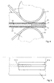
- Fig. 4 einen vergrössert dargestellten Querschnitt durch einen Teil der Vorrichtung gemäss Fig. 3 in Gebrauchslage beim Herstellen eines Isolierelementes;
- Fig. 5 eine Draufsicht auf den vergrössert dargestellten Ausschnitt der Vorrichtung entsprechend Fig. 4.
- 1 shows a cross section through an insulating element, in particular for use in refrigerator insulation.
- 2 shows a plan view of the insulating element according to FIG. 1;
- 3 shows a schematically represented side view of part of a device for producing the insulating element according to FIGS. 1 and 2;
- FIG. 4 shows an enlarged cross section through part of the device according to FIG. 3 in the position of use when producing an insulating element; FIG.
- 5 shows a plan view of the enlarged section of the device corresponding to FIG. 4.
Ein Isolierelement 1 zur Verwendung bei der Kühlschrankisolierung besteht gemäss Figur 1 aus einer Glasfaserplatte 2, die von einer Metallhülle 3 umgeben ist. Dabei besteht diese Metallhülle 3 aus einer Deckfolie 4 und einer Grundfolie 5. In den Kantenbereichen liegen Deckfolie 4 und Grundfolie 5 aufeinander und sind dort über entsprechende Schweissnähte 6, die in Figur 2 nur gestrichelt angedeutet sind, miteinander verbunden.According to FIG. 1, an
Das Verbinden der Deckfolie 4 und der Grundfolie 5 des Isolierelementes 1 erfolgt in einer Vorrichtung, welche in Figur 3 nur teilweise angedeutet ist. Hierbei ist an einem oberen und einem unteren Tragarm 7 bzw. 8 jeweils eine Rolle 9 bzw. 10 angeordnet, welche zumindest teilweise von einem Metalldraht 11 bzw. 12 umschlungen ist. Nach der Rolle 9 bzw. 10 wird der Metalldraht 11 bzw. 12 noch über eine weitere Führungsrolle 13 bzw. 14 geführt.The
Zur Erzeugung der Schweissnaht 6 im Randbereich von Deckfolie 4 und Grundfolie 5 wird das Isolierelement 1 zwischen den Rollen 9 und 10 hindurchgeführt, wobei der Metalldraht 11 bzw. 12 jeweils von einer Seite her auf der Deckfolie 4 bzw. der Grundfolie 5 abgerollt wird. Dabei werden Metalldraht 11 bzw. 12 in den Richtungen x1 bzw. x2 abgezogen.To produce the
Vor der Rolle 9 bzw. 10 ist dem Metalldraht 11 bzw. 12 eine Einrichtung 15 bzw. 16 zum Mikroprofilieren des Metalldrahtes 11 bzw. 12 zugeordnet. In einem einfachen Ausführungsbeispiel handelt es sich bei der Einrichtung 15 bzw. 16 zum Profilieren des Metalldrahtes 11 bzw. 12 um ein Schleifpapier 18, mit dem eine Stempelfläche 17 der Einrichtung 15 bzw. 16 belegt ist. Die Einrichtung 15 bzw. 16 zum Mikroprofilieren der Oberfläche des Metalldrahtes 11 bzw. 12 ist so angeordnet, dass die mikroprofilierte Oberfläche des Metalldrahtes auf der jeweiligen Deckfolie 4 bzw. Grundfolie 5 abrollt.In front of the
Nach dem Verbinden der Deckfolie 4 und Grundfolie 5 in den Randbereich über die Schweissnähte 6 erfolgt ein Evakuieren des Isolierelements 1 durch eine nicht näher gezeigte Öffnung in der Deckfolie 4, die im Anschluss daran mit einem Siegel 19 verschlossen wird.After the
In den Figuren 4 und 5 ist der Verbindungsbereich von Deckfolie 4 und Grundfolie 5 vergrössert dargestellt. Dabei ist erkennbar, dass sowohl Deckfolie 4 als auch Grundfolie 5 eine Oxydschicht 20 bzw. 21 aufweisen sind, welche aus einer verbindung besteht, die einen höheren Schmelzpunkt aufweist als die eigentliche Folie 4 bzw. 5.In FIGS. 4 and 5, the connection area between
Durch die Beaufschlagung des jeweiligen Metalldrahtes 11 bzw. 12 mit Strom erfolgt ein Aufschmelzen eines Bereiches zwischen den beiden Folien 4 und 5, die in diesem Bereich durch eine Schweissnaht 22 miteinander verbunden werden. Diese Schweissnaht 22 besteht aus einzelnen Schweisslinsen 23, die infolge des Durchführens des Isolierelementes 1 durch einen Spalt 24 zwischen den Metalldrähten und der Beaufschlagung der Metalldrähte 11 bzw. 12 mit Wechselstrom entstehen.By applying current to the
Claims (14)
Applications Claiming Priority (2)
| Application Number | Priority Date | Filing Date | Title |
|---|---|---|---|
| CH99596 | 1996-04-19 | ||
| CH995/96 | 1996-04-19 |
Publications (2)
| Publication Number | Publication Date |
|---|---|
| EP0802011A2 true EP0802011A2 (en) | 1997-10-22 |
| EP0802011A3 EP0802011A3 (en) | 1998-02-04 |
Family
ID=4200000
Family Applications (1)
| Application Number | Title | Priority Date | Filing Date |
|---|---|---|---|
| EP97102924A Withdrawn EP0802011A3 (en) | 1996-04-19 | 1997-02-22 | Method for joining two metal foils |
Country Status (5)
| Country | Link |
|---|---|
| US (1) | US6011236A (en) |
| EP (1) | EP0802011A3 (en) |
| JP (1) | JPH1029070A (en) |
| KR (1) | KR970069222A (en) |
| CA (1) | CA2199292A1 (en) |
Families Citing this family (3)
| Publication number | Priority date | Publication date | Assignee | Title |
|---|---|---|---|---|
| DE10306235B4 (en) * | 2003-02-14 | 2005-02-03 | Daimlerchrysler Ag | Method and arrangement for resistance seam welding of a film and at least one film carrier of a fuel cell system |
| JP6378471B2 (en) * | 2013-07-18 | 2018-08-22 | 日新製鋼株式会社 | Vacuum insulation panel |
| JP6143593B2 (en) * | 2013-07-18 | 2017-06-07 | 日新製鋼株式会社 | Vacuum insulation panel |
Citations (1)
| Publication number | Priority date | Publication date | Assignee | Title |
|---|---|---|---|---|
| US4795875A (en) * | 1985-07-01 | 1989-01-03 | Elpatronic Ag | Contact wire for a roller seam welding machine |
Family Cites Families (10)
| Publication number | Priority date | Publication date | Assignee | Title |
|---|---|---|---|---|
| US3654422A (en) * | 1966-07-26 | 1972-04-04 | Continental Can Co | Square wave resistance welding |
| CH595177A5 (en) * | 1976-11-09 | 1978-01-31 | Fael Sa | Ribbed copper electrode strip |
| JPS561281A (en) * | 1979-06-19 | 1981-01-08 | Toyo Seikan Kaisha Ltd | Method and device of welding treatment of can barrel |
| JPS5647281A (en) * | 1979-09-26 | 1981-04-28 | Toyo Seikan Kaisha Ltd | Method and device for producing welded metal can barrel |
| JPS5756173A (en) * | 1980-09-19 | 1982-04-03 | Daiwa Can Co Ltd | Electric resistance seaming and welding method of lateral joint of hollow cylindrical body |
| JPS59183987A (en) * | 1983-04-04 | 1984-10-19 | Kawasaki Heavy Ind Ltd | Method for preventing discoloration around indentation in spot welding |
| JPS59229290A (en) * | 1983-06-10 | 1984-12-22 | Nippon Kokan Kk <Nkk> | Electric resistance seam welding method |
| KR890002769B1 (en) * | 1983-09-09 | 1989-07-28 | 도오요오 세이깐 가부시기가이샤 | Method of making welded can body |
| JPS61206576A (en) * | 1985-03-11 | 1986-09-12 | Nepiyuu Giken:Kk | Welding method of lap joint of can body made of metallic plate and the like |
| US5389761A (en) * | 1993-09-17 | 1995-02-14 | General Motors Corporation | Method and apparatus for cleaning metal pieces prior to resistive seam welding or laser lap seam welding |
-
1997
- 1997-02-22 EP EP97102924A patent/EP0802011A3/en not_active Withdrawn
- 1997-03-04 US US08/811,547 patent/US6011236A/en not_active Expired - Fee Related
- 1997-03-05 CA CA002199292A patent/CA2199292A1/en not_active Abandoned
- 1997-04-11 KR KR1019970013460A patent/KR970069222A/en not_active Abandoned
- 1997-04-18 JP JP9101148A patent/JPH1029070A/en active Pending
Patent Citations (1)
| Publication number | Priority date | Publication date | Assignee | Title |
|---|---|---|---|---|
| US4795875A (en) * | 1985-07-01 | 1989-01-03 | Elpatronic Ag | Contact wire for a roller seam welding machine |
Also Published As
| Publication number | Publication date |
|---|---|
| US6011236A (en) | 2000-01-04 |
| EP0802011A3 (en) | 1998-02-04 |
| CA2199292A1 (en) | 1997-10-19 |
| KR970069222A (en) | 1997-11-07 |
| JPH1029070A (en) | 1998-02-03 |
Similar Documents
| Publication | Publication Date | Title |
|---|---|---|
| EP0189806B1 (en) | Method of butt welding at least one-side zinc-coated, especially deep-drawable steel sheets or steel bands | |
| DE69531975T2 (en) | Resistance projection welding processes | |
| DE1527875C3 (en) | Device for sheathing a cylindrical core made of aluminum with at least one metal sheathing strip made of copper | |
| EP0805733A1 (en) | Laser-assisted plating of strip | |
| DE69732292T2 (en) | METHOD AND DEVICE FOR PREPARING THERMOPLASTIC RESIN COATED METALLIC PLATE | |
| EP0004063B1 (en) | Process for producing clad plate | |
| DE2812415A1 (en) | PROCESS FOR PRODUCING WELDED SHEET METAL PROFILES AND DEVICE FOR CARRYING OUT THIS PROCESS | |
| DE3506011A1 (en) | Process for producing a multi-layered electrically heatable windscreen of plastic | |
| DE1905770C3 (en) | Device for build-up welding on metallic workpieces using a direct current arc | |
| EP0628399B1 (en) | Process for making a hollow tubular article | |
| DE3626470A1 (en) | METHOD FOR PRODUCING A TITANIUM-PLATED STEEL PLATE BY HOT ROLLERS | |
| EP0802011A2 (en) | Method for joining two metal foils | |
| DE1910743B2 (en) | DEVICE FOR CONTINUOUSLY CONNECTING A PLASTIC FILM TO A CARRIER | |
| EP0140834B1 (en) | Method of producing plated strips | |
| DE69419501T2 (en) | RESISTANCE WELDING PROCESS FOR STEEL AND ALUMINUM METAL PLATES AND RESISTANCE WELDING MATERIAL | |
| DE19606981C2 (en) | Process for the production of lightweight strips or sheets | |
| DE4022238C2 (en) | ||
| DE3630625C2 (en) | ||
| DE3722931C1 (en) | Electrode wire for a roller seam welding machine | |
| EP0166149A1 (en) | Electrode roll for electric resistance seam welding | |
| EP0145803A1 (en) | Method of producing hot-plated metallic strips | |
| DE2919365C2 (en) | Device for resistance tube seam welding | |
| DE3816541C1 (en) | Process for producing laminated metal composites, and use thereof | |
| DE3842865A1 (en) | Method of fabricating a longitudinally welded tube | |
| DE8103868U1 (en) | Device for the continuous production of endless, deformable tubes from a strip of laminate film |
Legal Events
| Date | Code | Title | Description |
|---|---|---|---|
| PUAI | Public reference made under article 153(3) epc to a published international application that has entered the european phase |
Free format text: ORIGINAL CODE: 0009012 |
|
| AK | Designated contracting states |
Kind code of ref document: A2 Designated state(s): BE CH DE ES FR GB IT LI NL PT |
|
| PUAL | Search report despatched |
Free format text: ORIGINAL CODE: 0009013 |
|
| AK | Designated contracting states |
Kind code of ref document: A3 Designated state(s): BE CH DE ES FR GB IT LI NL PT |
|
| 17P | Request for examination filed |
Effective date: 19980804 |
|
| RAP3 | Party data changed (applicant data changed or rights of an application transferred) |
Owner name: ELPATRONIC AG |
|
| 17Q | First examination report despatched |
Effective date: 19990930 |
|
| GRAP | Despatch of communication of intention to grant a patent |
Free format text: ORIGINAL CODE: EPIDOSNIGR1 |
|
| RTI1 | Title (correction) |
Free format text: METHOD AND APPARATUS FOR JOINING TWO METAL FOILS |
|
| RTI1 | Title (correction) |
Free format text: METHOD AND APPARATUS FOR JOINING TWO METAL FOILS |
|
| GRAS | Grant fee paid |
Free format text: ORIGINAL CODE: EPIDOSNIGR3 |
|
| STAA | Information on the status of an ep patent application or granted ep patent |
Free format text: STATUS: THE APPLICATION IS DEEMED TO BE WITHDRAWN |
|
| 18D | Application deemed to be withdrawn |
Effective date: 20031211 |