EP0802008B1 - Verfahren zum elektroerosiven Schneiden, sowie hierfür geeignete Vorrichtung - Google Patents
Verfahren zum elektroerosiven Schneiden, sowie hierfür geeignete Vorrichtung Download PDFInfo
- Publication number
- EP0802008B1 EP0802008B1 EP97105135A EP97105135A EP0802008B1 EP 0802008 B1 EP0802008 B1 EP 0802008B1 EP 97105135 A EP97105135 A EP 97105135A EP 97105135 A EP97105135 A EP 97105135A EP 0802008 B1 EP0802008 B1 EP 0802008B1
- Authority
- EP
- European Patent Office
- Prior art keywords
- wire
- guide
- erosion
- toroidal
- workpiece
- Prior art date
- Legal status (The legal status is an assumption and is not a legal conclusion. Google has not performed a legal analysis and makes no representation as to the accuracy of the status listed.)
- Expired - Lifetime
Links
- 238000000034 method Methods 0.000 title claims description 17
- 230000003628 erosive effect Effects 0.000 claims description 94
- 239000013598 vector Substances 0.000 claims description 6
- 238000011010 flushing procedure Methods 0.000 claims description 4
- 230000000694 effects Effects 0.000 description 9
- 238000005452 bending Methods 0.000 description 6
- 241001553014 Myrsine salicina Species 0.000 description 3
- 238000005259 measurement Methods 0.000 description 2
- 230000001419 dependent effect Effects 0.000 description 1
- 238000006073 displacement reaction Methods 0.000 description 1
- 230000006870 function Effects 0.000 description 1
- 238000003754 machining Methods 0.000 description 1
- 238000002360 preparation method Methods 0.000 description 1
- 230000003068 static effect Effects 0.000 description 1
Images

Classifications
-
- B—PERFORMING OPERATIONS; TRANSPORTING
- B23—MACHINE TOOLS; METAL-WORKING NOT OTHERWISE PROVIDED FOR
- B23H—WORKING OF METAL BY THE ACTION OF A HIGH CONCENTRATION OF ELECTRIC CURRENT ON A WORKPIECE USING AN ELECTRODE WHICH TAKES THE PLACE OF A TOOL; SUCH WORKING COMBINED WITH OTHER FORMS OF WORKING OF METAL
- B23H7/00—Processes or apparatus applicable to both electrical discharge machining and electrochemical machining
- B23H7/02—Wire-cutting
- B23H7/06—Control of the travel curve of the relative movement between electrode and workpiece
- B23H7/065—Electric circuits specially adapted therefor
Definitions
- the invention relates to a method and a device for electroerosive cutting of a workpiece using a EDM wire by at least one wire guide head is guided with a toroidal guide, in each case according to the generic terms of claims 1 and 11.
- Such devices with a toroidal guide are, for example known from DE 42 28 331 A1.
- Toroidal guides are particularly suitable for conical cuts.
- the DE 42 28 331 A1 provides two wire guides, one each the top and bottom of the workpiece in front, being on one side of each workpiece - in the following also as Main guide designated - open wire guide and a toroid guide are arranged, with the toroidal guide between the open wire guide and the workpiece.
- Main guide designated - open wire guide and a toroid guide are arranged, with the toroidal guide between the open wire guide and the workpiece.
- the open guidance ensures precise inclination Guiding the EDM wire.
- the toroidal guidance takes over the guidance of the Wire. Through this closed toroidal guide a The eroding wire slips out of the open wire guide avoided even with large conical angles.
- the inner diameter of the toroid and the arrangement of open wire guide and toroid guide are in DE 42 28 331 A1 selected such that the wire in the cylindrical or with a conical cut up to about two degrees of the open wire guides while he is at a conical angle of more than two degrees from the toroid becomes. It is therefore of the utmost importance to be the point of contact between wire and toroid.
- This will proposed in the generic DE 42 28 329 A1, the Position of the erosion wire inside or on the contour of the toroid.
- the target position in the workpiece is above that on the toroid corrected measured value corrected.
- a suitable wire position sensor at the top and bottom Toroid required.
- JP-A-61219528 is a closed guide to Leading the EDM wire known.
- the closed tour has a bore for guiding the EDM wire, the Diameter essentially the EDM wire diameter corresponds. This makes the EDM wire to everyone Time essentially in the horizontal direction (at vertical wire running direction) fixed at points. This stands in contrast to the toroidal guide, whose opening diameter a multiple of the EDM wire diameter can be and thereby the punctiform determination in Horizontal direction does not show.
- the invention aims at electroerosive cutting with toroidal guides.
- the method according to the invention or the one according to the invention manages with a toroidal guide.
- the invention also relates to erosion machines with several, in particular two, toroidal guides. Prefers Every toroidal guide is a main guide for guiding the Eroding wire assigned (claim 2).
- the subject of the invention allows the exact location of the Main guides with regard to the target positions of the erosion wire independently whether the wire touches the toroidal guide (s) or not, taking into account the relevant geometric and calculate physical parameters and the To derive (and carry out) the path of the main tours.
- the location (s) of the main guide (s) and / or toroid guide (s) with regard to the desired contour of the workpiece determined from the target position of the erosion wire and in Calculated in real time.
- An interpolation system of the wire EDM machine calculates successively, step by step Step, and in real time (e.g. every millisecond) which Position the wire guide heads, which are also the toroid guides and / or main tours included with regard to the Take the programmed target path according to the desired contour have to.
- This trajectory can result from pairs of points can be defined, whereby one point of a pair of points to the top of the workpiece and the other point the lower side of the workpiece is covered.
- the use of wire position sensors can be used to be dispensed with, so that this builds up a Erosion machine simplified, i.e. the electrical discharge machine manages with fewer system components. she not only becomes cheaper, but also less prone to failure.
- the above-mentioned position calculation takes into account advantageously the spatial direction of the EDM wire, the Following error, the relative cutting speed at the top and bottom of the workpiece, the rigidity of the erosion wire and / or the eccentricity of the toroidal guide in relation to the main tour (claim 3).
- working point denotes in Connection with the invention in a (ideally) infinitely flexible EDM wire the geometric center on the circular arc - hereinafter also the line of contact called - where the toroidal guide and the erosion wire touch.
- the line of contact shrinks stiffness to a point of contact, which then with the working point coincides.
- the EDM wire would tangentially the toroidal guide in a first Touch the point, the curvature of the toroidal guide up to one Follow the second point and there again tangentially the toroidal guide towards the entry point of the erosion wire leave in the workpiece.
- the EDM wire has a certain rigidity, i.e. not infinite is flexible, touches the EDM wire, especially because of of the small bending radius of the toroidal guide, the toroidal guide only in the above-mentioned working point, which is on the toroid surface in the middle between the first and the second point.
- the curvature of the erosion wire can be advantageous with the help of - from the statics known - calculate "bar theory".
- the wire redirection approximately in the wires used in practice only within a few millimeters of the working point takes place, the wire is at the entrance into the workpiece again on a perfect straight line. However, a first is created at the point of entry into the workpiece Offset. This offset is accompanied by an error of the conical angle. The rigidity is therefore advantageous of the EDM wire at the above Location calculation taken into account.
- a second offset occurs due to the eccentricity of one Toroidal guide to the assigned main guide, for example due to mechanical tolerances or else as a result arises that uses EDM wires of different thickness and the arrangements of toroidal guides and Main guides are not displaceable relative to each other. Because of this second offset, another one arises Shift of the working point. This shift causes a shift in the position of the eroding wire with respect to the toroidal guide.
- the eccentricity of the toroidal guide is therefore advantageous regarding the main tour at the above Location calculation considered.
- the following error is particularly advantageous, in particular as lag error vector, from the momentary ones underlying erosion Erosion parameters, especially the Flushing pressure, the cutting speed, the eroding forces, the pulse frequency, the erosion current and / or the erosion voltage determined (claim 5). Knowing the erosion parameters, which can be known, for example, in that they are preset or during the erosion process be successively redetermined, or also measured the following error can be determined without that separate wire position sensors must be used.
- the locations of two main guides are particularly advantageous compared to the target position of the EDM wire above and calculated independently of each other below the workpiece, um, especially in the case of conical cuts different cutting speeds above and below of the workpiece setting - difference of Lag errors above and below the workpiece must be taken into account (Claim 6). This way there can be deviations the following error above and below the workpiece, which amount to up to +/- 15% of a following error can be taken into account. Thus, the accuracy the position calculations are further increased.
- the stiffness of the erosion wire is preferably determined by comparing one or more measured taper angles with one or more set taper angles (claim 9). Since the rigidity or the modulus of elasticity E of the erosion wire is not always exactly known, a "calibration" of the above formula is very useful. This calibration is carried out by measuring the real conical angle in relation to the set conical angle over a certain or the entire angular range with the aid of an appropriate calibration device. The elastic modulus E for a specific wire type can be determined in each case from these measurement data, which can be obtained once with a reference measurement. In principle, this value can also be dependent on the bending data of the erosion wire, such as, for example, the bending radius and / or the angle of the bend.
- the values obtained for the modulus of elasticity E can then be taken into account when calculating the first conical error ⁇ by reading out the values for the modulus of elasticity E from a suitable memory.
- the eccentricity of the toroidal guide with respect to the main guide assigned to it is preferably calculated from the equilibrium state of the components of the tensile forces which are tangential to the toroidal guide and which stress the eroding wire in the longitudinal direction of the wire (claim 10).
- the toroidal guide can be simplified as a circle. Tangential force components of the tensile forces act on the toroidal guide tangentially to this circle, which stress the eroding wire in front of and behind the toroidal guide.
- the working point will now be set at the point where the tangential force components are in equilibrium with each other. Based on this condition, the working point can be calculated with knowledge of the tensile forces in the erosion wire and the eccentricity. In this way, a new position of the toroidal guide (s) can then be calculated with regard to the desired contour of the workpiece.
- the device already mentioned above can advantageously be a Method according to one or more of the configurations explained above carry out Regarding individual features and advantages of the device reference is made to the above explanations of the method, which fully refer to the device in their relate to different configurations.
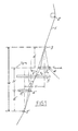
- Fig. 1 is limited to a purely schematic representation essential parts of a wire EDM machine Toroidal guides.
- An eroding wire 1 becomes one - not shown - wire transport device from “above” to Fast forward "below”.
- a power supply 2 is used for supply that of a generator of the wire EDM machine emitted electrical impulses. The power supply ensures this 2 also for a certain pre-tensioning of the erosion wire 1.
- Below the power supply 2 is an upper one open wire guide 3 - also called upper main guide - arranged.
- the upper open wire guide 3 is V-shaped trained so that the eroding wire 1 in its rest position lies in the "lowest point" of the "V".
- Below the top open wire guide 3 is a closed wire guide, namely an upper toroidal guide 4 arranged. The leadership of the erosion wire 1 thus takes place through the arrangement open wire guide 3 with toroid guide 4.
- the workpiece is located below the toroidal guide 4 5 and again below the workpiece 5 a lower toroidal guide 4 ', which is horizontally opposite the upper toroidal guide 4 is shifted by the length V.
- a lower toroidal guide 4 ' which is horizontally opposite the upper toroidal guide 4 is shifted by the length V.
- Below is the lower toroidal guide 4 ' lower open wire guide 3 'at vertical distance d'.
- the upper open wire guide 3 is relative to the upper Toroidal guide 4 at a distance d.
- the inner radius the upper toroidal guide is R and the inner radius the lower toroidal guide is R '.
- the distance between upper open wire guide 3 and lower open wire guide 3 ' is Q.
- the open wire guide 3 takes over the guiding of the erosion wire 1.
- the angle ⁇ border is, for example, 2 °.
- the eroding wire 1 does not fall out of the open wire guide 3 because of its pretension.
- the toroidal guide 4 takes over the wire guide.
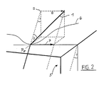
- Fig. 2 shows the first effect in the position correction of a wire guide head must be taken into account. It is the following error B, which is at a flexible EDM wire 1 always during processing of a workpiece 5. The following error B expresses in a bulge of the erosion wire 1 against the Cutting direction, the eroding wire 1 due to the eroding forces and is pushed back by the flushing pressure.
- the following error B can also be characterized by the following angle ⁇ .
- the drag angle ⁇ is the angle between the straight line which is described by the eroding wire 1 in the workpiece to the straight line which is described by the eroding wire 1 outside the workpiece.
- the eroding wire 1 the desired contours on the top and bottom of the workpiece 5 follows must to the target position S as the correction value of the following error B to take the drag angle ⁇ into account vectorially Cutting direction 7 can be added.
- the tracking error B or drag angle ⁇ can be determined from the current erosion parameters and from the known geometry of the calculate the intersecting contour. Amount and direction of the Following error vectors are calculated separately.
- the vector amount is calculated from the current one Working current and the current working voltage and off the instantaneous pressure of the flush flowing around the cutting wire, while the vector direction is calculated from the angle between the direction of the following error End of a path element of the contour curve and the direction of the path element of the contour curve to be cut next results.
- the target position is related to the main guide 3 (not shown). Consequently, the target position S of the main guide 3 results from the following error B and the correction value K toro .
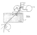
- FIG. 4 shows a schematic lateral section through the toroidal guides 4, 4 'and the workpiece 5.
- An ideal eroding wire 1 ideal which is additionally idealized here as a line - ie with a punctiform cross section - would, as shown in FIG. 3, run along the dashed line.
- the erosion wire 1 actually has a certain rigidity. This real course is shown in FIG. 4 by means of the solid line.
- the consequence of the rigidity is that the eroding wire 1 actually touches the toroidal guide only at one point C, in particular because of the small bending radius R B of the toroidal guide 4.
- This point also known as the working point
- the radius of this circular arc is equal to the bending radius of the toroidal guide.
- the real EDM wire 1 real thus ideally receives a new curvature compared to the ideal EDM wire 1, which can be calculated using the so-called "bar theory".
- the wire deflection takes place within a few millimeters around the contact point C, so that the EDM wire 1 is actually on a perfect straight line again when entering the workpiece 5, namely the line shown in ideal dashed lines for the ideal EDM wire 1.
- the eroding wire 1 real experiences a first offset ⁇ with respect to the ideal line, which is described by the straight line connecting the points A and A '.
- This first offset ⁇ causes an error in the conical angle — referred to as the conical error ⁇ .
- the straight line through points A and A ' is perpendicular to the bending radii R B to points A and A'.
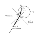
- TF w denotes the force that can be generated when the force F w is decomposed and acts tangentially to the circle of the toroidal guide 4. Accordingly, TF f characterizes the force that acts tangentially to the circle of the toroidal guide 4 when the force F f is decomposed.
- Fig. 5 shows that the working point of the erosion wire 1 is where the tangential force components TF f and TF w are in equilibrium with each other.
- the effects described above can be one calculate the other in real time until final determination the positions of the main guides and / or toroid guides.
- the logical order, however, is important which the displacements are calculated: Because of the The non-linearity of some effects must be calculated by everyone Shift caused by the previous effects Take shifts into account.
Landscapes
- Chemical & Material Sciences (AREA)
- Chemical Kinetics & Catalysis (AREA)
- Electrochemistry (AREA)
- Engineering & Computer Science (AREA)
- Mechanical Engineering (AREA)
- Electrical Discharge Machining, Electrochemical Machining, And Combined Machining (AREA)
Applications Claiming Priority (2)
| Application Number | Priority Date | Filing Date | Title |
|---|---|---|---|
| DE19614133A DE19614133A1 (de) | 1996-04-10 | 1996-04-10 | Verfahren zum elektroerosiven Schneiden, sowie hierfür geeignete Vorrichtung |
| DE19614133 | 1996-04-10 |
Publications (2)
| Publication Number | Publication Date |
|---|---|
| EP0802008A1 EP0802008A1 (de) | 1997-10-22 |
| EP0802008B1 true EP0802008B1 (de) | 2001-05-02 |
Family
ID=7790877
Family Applications (1)
| Application Number | Title | Priority Date | Filing Date |
|---|---|---|---|
| EP97105135A Expired - Lifetime EP0802008B1 (de) | 1996-04-10 | 1997-03-26 | Verfahren zum elektroerosiven Schneiden, sowie hierfür geeignete Vorrichtung |
Country Status (5)
| Country | Link |
|---|---|
| US (1) | US5922220A (ja) |
| EP (1) | EP0802008B1 (ja) |
| JP (1) | JP3222088B2 (ja) |
| DE (2) | DE19614133A1 (ja) |
| ES (1) | ES2156315T3 (ja) |
Families Citing this family (4)
| Publication number | Priority date | Publication date | Assignee | Title |
|---|---|---|---|---|
| US6612043B2 (en) * | 2001-06-08 | 2003-09-02 | Industrial Technology Research Institute | Method and apparatus for vertically calibrating wire of wire cutting electric discharge machine |
| EP1291110B1 (de) * | 2001-09-11 | 2013-07-10 | Agie Charmilles SA | Funkenerosives Verfahren und Vorrichtung zur Mehrdrahtbearbeitung |
| JP5088975B2 (ja) * | 2010-10-19 | 2012-12-05 | 株式会社ソディック | ワイヤ放電加工装置 |
| JP4938137B1 (ja) * | 2011-03-03 | 2012-05-23 | ファナック株式会社 | 被加工物の上面検出機能を有するワイヤカット放電加工機 |
Family Cites Families (12)
| Publication number | Priority date | Publication date | Assignee | Title |
|---|---|---|---|---|
| JPS59232727A (ja) * | 1983-06-14 | 1984-12-27 | Fanuc Ltd | ワイヤカツト放電加工用ワイヤ電極ガイド装置 |
| JPS61182729A (ja) * | 1985-02-09 | 1986-08-15 | Fanuc Ltd | ワイヤカツト放電加工機のテ−パ加工制御装置 |
| JPS61219528A (ja) * | 1985-03-27 | 1986-09-29 | Fanuc Ltd | ワイヤカツト放電加工装置 |
| CH665374A5 (fr) * | 1985-03-28 | 1988-05-13 | Charmilles Technologies | Procede et dispositif pour la determination de la fleche d'un fil a decouper par electroerosion. |
| JPS61288929A (ja) * | 1985-06-15 | 1986-12-19 | Fanuc Ltd | ワイヤカツト放電加工機 |
| JPS62120919A (ja) * | 1985-11-20 | 1987-06-02 | Fanuc Ltd | ワイヤカツト放電加工方法 |
| JP2518337B2 (ja) * | 1988-01-27 | 1996-07-24 | ブラザー工業株式会社 | ワイヤ放電加工機のテ―パ加工装置 |
| US5003147A (en) * | 1989-05-12 | 1991-03-26 | Brother Kogyo Kabushiki Kaisha | Method of measuring wire guide spans and directing wire electrode perpendicularly to reference machining plane in electrical-discharge wire cutting machine |
| DE4228329C2 (de) * | 1992-08-26 | 1996-08-22 | Agie Ag Ind Elektronik | Vorrichtung und Verfahren zum Führen der Drahtelektrode beim funkenerosiven Schneiden |
| DE4228331A1 (de) * | 1992-08-26 | 1994-03-03 | Agie Ag Ind Elektronik | Elektroerosions-Schneidvorrichtung |
| US5440492A (en) * | 1992-12-23 | 1995-08-08 | Kozah; Ghassan F. | Kinematically positioned data acquisition apparatus and method |
| DE19614134C2 (de) * | 1996-04-10 | 2002-06-13 | Agie Sa | Drahterosionsmaschine und Verfahren zu deren Betrieb |
-
1996
- 1996-04-10 DE DE19614133A patent/DE19614133A1/de not_active Withdrawn
-
1997
- 1997-03-26 DE DE59703460T patent/DE59703460D1/de not_active Expired - Lifetime
- 1997-03-26 ES ES97105135T patent/ES2156315T3/es not_active Expired - Lifetime
- 1997-03-26 EP EP97105135A patent/EP0802008B1/de not_active Expired - Lifetime
- 1997-04-09 US US08/837,314 patent/US5922220A/en not_active Expired - Lifetime
- 1997-04-10 JP JP10682997A patent/JP3222088B2/ja not_active Expired - Fee Related
Also Published As
| Publication number | Publication date |
|---|---|
| US5922220A (en) | 1999-07-13 |
| JPH1034444A (ja) | 1998-02-10 |
| DE59703460D1 (de) | 2001-06-07 |
| DE19614133A1 (de) | 1997-10-16 |
| EP0802008A1 (de) | 1997-10-22 |
| JP3222088B2 (ja) | 2001-10-22 |
| ES2156315T3 (es) | 2001-06-16 |
Similar Documents
| Publication | Publication Date | Title |
|---|---|---|
| EP0801341B1 (de) | Drahterosionsmaschine und Verfahren zu deren Betrieb | |
| DE102018002566B4 (de) | Steuervorrichtung für eine Oszillationschneiden durchführende Werkzeugmaschine | |
| DE2635766C2 (de) | Verfahren und Vorrichtung zur Funkenerosionsbearbeitung | |
| DE19506522A1 (de) | Verfahren und Vorrichtung zum Laserschneiden | |
| EP0209792B1 (de) | Verfahren zur gesteuerten Rückzugsbewegung einer Senkelektrode bei einer Elektroerosionsmaschine | |
| EP0873813B1 (de) | Laserschneidmaschine und Verfahren zum Laserschneiden | |
| DE2818801A1 (de) | Vibrationsvorrichtung | |
| EP0585716B1 (de) | Vorrichtung und Verfahren zum elektroerosiven Schneiden | |
| WO1990001673A1 (de) | Messvorrichtung zur querprofilmessung einer papierbahn | |
| DE69615622T2 (de) | Verfahren und Vorrichtung zur Steuerung des Ziehens von Walzgut zwischen Walzgerüste | |
| EP0802008B1 (de) | Verfahren zum elektroerosiven Schneiden, sowie hierfür geeignete Vorrichtung | |
| DE3517475C2 (ja) | ||
| DE69603223T2 (de) | Elektroerosive Bearbeitungseinrichtung | |
| DE102005039094A1 (de) | Verfahren und Vorrichtung zum Führen eines Maschinenteils entlang einer definierten Bewegungsbahn über einer Werkstücksoberfläche | |
| DE112015001760T5 (de) | Drahterodiermaschine, Steuerungsverfahren einer Steuerung einer Drahterodiermaschine und Positionierungsverfahren | |
| EP0585714B1 (de) | Elektroerosions-Schneidvorrichtung | |
| DE19614200C2 (de) | Verfahren zum Bewegen wenigstens eines Führungskopfes einer Drahterosionsmaschine, sowie Drahterosionsmaschine mit einer Stelleinrichtung zum Durchführen von Bewegungen wenigstens eines Führungskopfes | |
| EP0781620B1 (de) | Verfahren und Vorrichtung zum Drahterodieren | |
| DE3038747C2 (ja) | ||
| DE69011537T2 (de) | Steuerungseinrichtung und Verfahren zum elektroerosiven Schneiden mittels einer Drahtelektrode. | |
| DE2841481A1 (de) | Verfahren und anordnung zum bestimmen der einstellung des anfaenglichen walzenspaltes in einem metallwalzwerk | |
| EP0603534A1 (de) | Vorrichtung und Verfahren zum elektroerosiven Schneiden | |
| DE10103292A1 (de) | Elektrodenführung für Erodiermaschinen sowie Verfahren zum Erodieren von Werkstücken | |
| DE3321010C2 (ja) | ||
| EP4367561A1 (de) | Verfahren zur kompensation einer abdrängung eines werkzeugs bei einer bearbeitung eines werkstücks sowie werkzeugmaschine hierzu |
Legal Events
| Date | Code | Title | Description |
|---|---|---|---|
| PUAI | Public reference made under article 153(3) epc to a published international application that has entered the european phase |
Free format text: ORIGINAL CODE: 0009012 |
|
| AK | Designated contracting states |
Kind code of ref document: A1 Designated state(s): CH DE ES FR GB IT LI NL |
|
| 17P | Request for examination filed |
Effective date: 19971030 |
|
| RAP1 | Party data changed (applicant data changed or rights of an application transferred) |
Owner name: AGIE SA |
|
| 17Q | First examination report despatched |
Effective date: 19990211 |
|
| GRAG | Despatch of communication of intention to grant |
Free format text: ORIGINAL CODE: EPIDOS AGRA |
|
| GRAG | Despatch of communication of intention to grant |
Free format text: ORIGINAL CODE: EPIDOS AGRA |
|
| GRAH | Despatch of communication of intention to grant a patent |
Free format text: ORIGINAL CODE: EPIDOS IGRA |
|
| GRAH | Despatch of communication of intention to grant a patent |
Free format text: ORIGINAL CODE: EPIDOS IGRA |
|
| GRAA | (expected) grant |
Free format text: ORIGINAL CODE: 0009210 |
|
| AK | Designated contracting states |
Kind code of ref document: B1 Designated state(s): CH DE ES FR GB IT LI NL |
|
| REG | Reference to a national code |
Ref country code: CH Ref legal event code: EP |
|
| GBT | Gb: translation of ep patent filed (gb section 77(6)(a)/1977) |
Effective date: 20010502 |
|
| REF | Corresponds to: |
Ref document number: 59703460 Country of ref document: DE Date of ref document: 20010607 |
|
| REG | Reference to a national code |
Ref country code: ES Ref legal event code: FG2A Ref document number: 2156315 Country of ref document: ES Kind code of ref document: T3 |
|
| ET | Fr: translation filed | ||
| ITF | It: translation for a ep patent filed | ||
| REG | Reference to a national code |
Ref country code: GB Ref legal event code: IF02 |
|
| PLBE | No opposition filed within time limit |
Free format text: ORIGINAL CODE: 0009261 |
|
| STAA | Information on the status of an ep patent application or granted ep patent |
Free format text: STATUS: NO OPPOSITION FILED WITHIN TIME LIMIT |
|
| 26N | No opposition filed | ||
| PGFP | Annual fee paid to national office [announced via postgrant information from national office to epo] |
Ref country code: NL Payment date: 20080318 Year of fee payment: 12 |
|
| NLV4 | Nl: lapsed or anulled due to non-payment of the annual fee |
Effective date: 20091001 |
|
| PG25 | Lapsed in a contracting state [announced via postgrant information from national office to epo] |
Ref country code: NL Free format text: LAPSE BECAUSE OF NON-PAYMENT OF DUE FEES Effective date: 20091001 |
|
| REG | Reference to a national code |
Ref country code: FR Ref legal event code: PLFP Year of fee payment: 19 |
|
| PGFP | Annual fee paid to national office [announced via postgrant information from national office to epo] |
Ref country code: CH Payment date: 20150319 Year of fee payment: 19 Ref country code: ES Payment date: 20150326 Year of fee payment: 19 Ref country code: IT Payment date: 20150326 Year of fee payment: 19 Ref country code: DE Payment date: 20150320 Year of fee payment: 19 |
|
| PGFP | Annual fee paid to national office [announced via postgrant information from national office to epo] |
Ref country code: GB Payment date: 20150319 Year of fee payment: 19 Ref country code: FR Payment date: 20150319 Year of fee payment: 19 |
|
| REG | Reference to a national code |
Ref country code: DE Ref legal event code: R119 Ref document number: 59703460 Country of ref document: DE |
|
| REG | Reference to a national code |
Ref country code: CH Ref legal event code: PL |
|
| GBPC | Gb: european patent ceased through non-payment of renewal fee |
Effective date: 20160326 |
|
| REG | Reference to a national code |
Ref country code: FR Ref legal event code: ST Effective date: 20161130 |
|
| PG25 | Lapsed in a contracting state [announced via postgrant information from national office to epo] |
Ref country code: DE Free format text: LAPSE BECAUSE OF NON-PAYMENT OF DUE FEES Effective date: 20161001 Ref country code: LI Free format text: LAPSE BECAUSE OF NON-PAYMENT OF DUE FEES Effective date: 20160331 Ref country code: CH Free format text: LAPSE BECAUSE OF NON-PAYMENT OF DUE FEES Effective date: 20160331 Ref country code: FR Free format text: LAPSE BECAUSE OF NON-PAYMENT OF DUE FEES Effective date: 20160331 Ref country code: GB Free format text: LAPSE BECAUSE OF NON-PAYMENT OF DUE FEES Effective date: 20160326 |
|
| PG25 | Lapsed in a contracting state [announced via postgrant information from national office to epo] |
Ref country code: IT Free format text: LAPSE BECAUSE OF NON-PAYMENT OF DUE FEES Effective date: 20160326 |
|
| REG | Reference to a national code |
Ref country code: ES Ref legal event code: FD2A Effective date: 20170426 |
|
| PG25 | Lapsed in a contracting state [announced via postgrant information from national office to epo] |
Ref country code: ES Free format text: LAPSE BECAUSE OF NON-PAYMENT OF DUE FEES Effective date: 20160327 |