EP0801955B1 - Aide d'introduction pour fil de guidage - Google Patents
Aide d'introduction pour fil de guidage Download PDFInfo
- Publication number
- EP0801955B1 EP0801955B1 EP96106109A EP96106109A EP0801955B1 EP 0801955 B1 EP0801955 B1 EP 0801955B1 EP 96106109 A EP96106109 A EP 96106109A EP 96106109 A EP96106109 A EP 96106109A EP 0801955 B1 EP0801955 B1 EP 0801955B1
- Authority
- EP
- European Patent Office
- Prior art keywords
- clamping
- passage
- insertion aid
- guidewire
- catheter
- Prior art date
- Legal status (The legal status is an assumption and is not a legal conclusion. Google has not performed a legal analysis and makes no representation as to the accuracy of the status listed.)
- Expired - Lifetime
Links
Images


Classifications
-
- A—HUMAN NECESSITIES
- A61—MEDICAL OR VETERINARY SCIENCE; HYGIENE
- A61M—DEVICES FOR INTRODUCING MEDIA INTO, OR ONTO, THE BODY; DEVICES FOR TRANSDUCING BODY MEDIA OR FOR TAKING MEDIA FROM THE BODY; DEVICES FOR PRODUCING OR ENDING SLEEP OR STUPOR
- A61M25/00—Catheters; Hollow probes
- A61M25/01—Introducing, guiding, advancing, emplacing or holding catheters
- A61M25/09—Guide wires
- A61M25/09041—Mechanisms for insertion of guide wires
Definitions
- the invention relates to an insertion aid to facilitate insertion of the proximal end of a guidewire into the distal end of a catheter as defined in the precharacterizing part of claim 1.
- a guide catheter When a patient is subjected to a vascular treatment necessitating employment of a catheter, a guide catheter is first inserted into the vessel in which the catheter is to be employed, after which a guidewire is introduced in this guide catheter. Via this guidewire the actual treatment catheter is then advanced up to the point at which the treatment procedure is to be implemented.
- the treatment catheter has for this purpose a passage beginning at its tip which extends over a certain portion or over the full length of the catheter and serves to receive the guidewire. This means that the proximal end of the guidewire needs to be inserted in the opening of this passage at the distal end of the catheter.
- the passage in the treatment catheter has an inner diameter which is only slightly greater than the outer diameter of the guidewire, insertion is difficult, it thereby needing to be taken into account that the complete treatment procedure is required to be implemented in as short a time as possible to reduce the stress on the patient.
- An insertion aid of the type defined above is disclosed in EP-A-0 328 760.
- This insertion aid consist of two pieces.
- the two pieces have to be manufactured with closed tolerances in order to provide a smooth internal channel for the guidewire.
- US-A-4 838 880 discloses an insertion aid comprising movable and stationary jaws operably and closably connected together by means of a thin hinge.
- This inserter can only be used together with a cup-like housing into which the converged or tapered end is to be inserted. Therefore, the inserter as such is not suitable for inserting the proximal end of a guidewire into the distal end of a catheder.
- the invention is thus based on the object of defining an insertion aid of the kind as stated at the outset which is simple and cost-effective in manufacture, permitting introduction of the guidewire speedily and safely into the distal end of the catheter and which is subsequently easily removable from the guidewire.
- the distal end of the catheter is insertable from one side into the passage formed between the clamping surfaces, the proximal end of the guidewire then being introduced from the other side into the passage which is flared funnel-shaped at both ends.
- the passage can be opened so that the insertion aid can be moved away laterally from the guidewire, the insertion aid thus no longer disturbing further treatment.
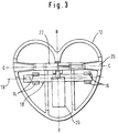
- the insertion aid 10 illustrated in Fig. 1 consists of two identical clamping pieces 12 which have a heart-shaped contour. Two of these clamping pieces 12 may be joined together like a clothes clamp. How and by what means this joining together is done is explained with reference to Figs. 2 and 3 which show the internal side of the clamping piece 12 facing away in Fig. 1.
- Fig. 2 gripping elements 14, 16 are provided on the internal surface which as shown by the section views of Figs. 4 and 5 each consist of two arcuate pieces between which a pin 18 may be pressed that carries in its middle portion a leaf spring 20.
- the combination of the pin 18 and the leaf spring 20 is illustrated in Fig. 6, the side view of Fig. 7 making it evident that the leaf spring 20 is configured U-shaped and is connected to the pin 18 in the region of its bend so that two sections 18a and 18b extend away from this bend.
- both clamping pieces 12 are fixedly latched to the pin 18 and the leaf spring 20, due to its U-shape thus acts against the clamping pieces 12 so that their ends located at the bottom in Figs. 2 and 3 are spread apart.
- the clamping pieces behave like two-armed levers, the pivot axis of which is formed by the axis 19 of the pin 18. They are movable between a closed clamp position and an open release position.
- FIG. 8 In the side view of Fig. 8 two clamping parts 12 connected to each other by latching on the pin 18 are illustrated in the clamp position in which the ends located at the bottom in Fig. 8 of the leaf spring 20 are spread apart, whereby to assist distinguishing the clamping parts are denoted 12a and 12b.
- Figs. 10 and 11 show the insertion aid 10 in the positions of Figs. 8 and 9, but each in sections along the line A-A of Fig. 1.
- a clamping surface 22 is evident which is maintained in the clamping position of the insertion aid of Fig. 8 by the leaf spring 20 in contact with the corresponding clamping surface 22 of the other clamping piece 12.
- a depression is provided which is flared funnel-shaped towards the end located on the right in Fig. 2 of the clamping surface 22.
- a magnified section of the clamping surface 22 with the depression 24 provided therein is illustrated in Fig. 12.
- Fig. 13 shows a section along the line 13-13 of Fig. 12, only the section of the clamping piece 12 being illustrated in which the clamping surface 22 is located.
- the depression 24 is flared in two steps funnel-like towards the end located on the right in Fig. 12. Due to this steplike flaring evident in Fig. 13 perpendicular to the longitudinal direction of the depression a flaring also results in this perpendicular direction.
- the clamping surface 22 has a non-recessed planar surface. In the middle portion this planar surface translates directly into the bottom of the first depression adjoining the middle on the right. This middle portion is followed by a further non-recessed portion of the clamping surface with a step transition.
- the passage 25 has an interior dimension corresponding to the outer diameter of the catheter into which the guidewire is to be introduced.
- the insertion aid as described is put to use in practical application as follows:
- the guidewire When in treatment requiring the use of a catheter the guidewire is already inserted in the vessel to be treated, the proximal end of the guidewire then needs to be inserted into the distal end of the treatment catheter.
- the distal end of the treatment catheter is introduced as far as possible into the funnel-shaped flared end of the passage of the insertion aid.
- the proximal end of the guidewire is introduced into the other funnel-shaped flared end of the passage of the insertion aid until it penetrates the distal end of the treatment catheter. Due to the centered position of the distal end of the treatment catheter the guidewire can be introduced into the catheter with no appreciable difficulty so that no waste of time occurs in this phase of the treatment procedure.
- a treatment catheter 23 indicated by a dashed line in Fig. 2 is inserted into the passage 25 from the right. Its distal end is located in the portion 25a in which the interior dimension of the passage roughly corresponds to the outer diameter of the catheter.
- the insertion aid is no longer required.
- the former By pressing the ends located at the bottom in Fig. 8 of the clamping piece the former are pivoted about the pin 18 against the action of the leaf spring into the position illustrated in Fig. 9 so that the passage originally closed in the clamping surface 22 is opened.
- the insertion aid can then be removed directly laterally from the treatment catheter and from the inserted guidewire.
- the clamping pieces may be manufactured cost-effectively as injection molded items since they are totally identical, thus requiring only a single injection mold. Due to the special position of the gripping elements 14, 16 and the configuration of the clamping surface 22 along with the depression 24 formed therein, the clamping piece are to be manufactured totally identical.
Landscapes
- Health & Medical Sciences (AREA)
- Life Sciences & Earth Sciences (AREA)
- Biophysics (AREA)
- Pulmonology (AREA)
- Engineering & Computer Science (AREA)
- Anesthesiology (AREA)
- Biomedical Technology (AREA)
- Heart & Thoracic Surgery (AREA)
- Hematology (AREA)
- Animal Behavior & Ethology (AREA)
- General Health & Medical Sciences (AREA)
- Public Health (AREA)
- Veterinary Medicine (AREA)
- Media Introduction/Drainage Providing Device (AREA)
- Paper (AREA)
- Electrical Discharge Machining, Electrochemical Machining, And Combined Machining (AREA)
- Knitting Machines (AREA)
- Surgical Instruments (AREA)
- Orthopedics, Nursing, And Contraception (AREA)
- Vending Machines For Individual Products (AREA)
- Measurement Of The Respiration, Hearing Ability, Form, And Blood Characteristics Of Living Organisms (AREA)
Claims (4)
- Dispositif d'aide à l'insertion pour faciliter l'insertion de la partie extrême proximale d'un fil de guidage dans la partie extrême distale d'un cathéter, comprenant :deux pièces de serrage (12a, 12b) pouvant être disposées dans une position fermée de serrage ou dans une position ouverte de dégagement,des moyens (20) qui maintiennent des surfaces de serrage (22), chacune d'elles étant prévue sur chacune des pièces de serrage, positivement en contact l'une avec l'autre en position de serrage,lesdites surface de serrage (22), lorsqu'elles sont en contact l'une avec l'autre, définissant un passage (25) ouvert aux deux extrémités,ledit passage (25) contenant une section (25a) ayant une dimension intérieure adéquate pour loger un cathéter, et étant évasé en forme d'entonnoir au niveau de ses deux extrémités,lesdites surfaces de serrage (22), en position de dégagement, ouvrant latéralement le passage (25) pour enlever le fil de guidage,
caractérisée en ce quelesdites pièces de serrage (12a, 12b)ont la forme d'un levier comprenant deux bras, etsont articulées l'une par rapport à l'autre pour pivoter autour d'un axe commun entre la position fermée de serrage et la position ouverte de dégagement,chacune desdites surfaces de serrage (22) est prévue sur un bras de chacune des pièces de serrage (12a, 12b),lesdits moyens, qui maintiennent les surfaces de serrage positivement en contact l'une avec l'autre en position de serrage, sont des moyens formant ressort (20),ledit passage (25) estorienté de façon parallèle audit axe commun, etformé par un creux (24) prévu dans une moitié de chacune des surfaces de serrage (22),la section transversale dudit creux (24) correspondant audit passage (25) à réaliser, la longueur axiale dudit creux correspondant à la moitié de la longueur dudit passage (25),le plan de ladite surface de serrage (22) coïncidant dans la partie médiane de sa moitié non dotée d'un creux, avec le fond du creux adjacent dans l'autre moitié. - Dispositif d'aide à l'insertion selon la revendication 1, où ledit passage a une section transversale carrée.
- Dispositif d'aide à l'insertion selon l'une quelconque des revendications 1 ou 2, dans lequel lesdits moyens formant ressort sont un ressort à lame (20) recourbé en forme de U, ligne de courbure le long de laquelle une goupille (18) est prévue qui comprend deux parties (18a, 18b) faisant saillie des deux côtés du ressort à lame (20),et dans lequel sur les côtés desdites pièces de serrage (12a, 12b) supportant ladite surface de serrage (22), des éléments de préhension (14, 16) sont prévus qui sont verrouillables avec ladite goupille (18), de façon que ladite goupille (18) forme l'axe pivot commun (C-C) desdites pièces de serrage (12), et dans laquelle ledit ressort à lame (20) est maintenu tendu entre lesdites deux pièces de serrage (12a, 12b), ledit ressort à lames (20), dans cette position, écartant les deux bras desdites pièces de serrage (12a, 12b) et, ce faisant, maintenant lesdites surfaces de serrage (22) en contact l'une avec l'autre.
- Dispositif d'aide à l'insertion selon l'une quelconque des revendications 1 à 3, où lesdites pièces de serrage (12) sont configurées comme des pièces identiques moulées par injection.
Priority Applications (9)
| Application Number | Priority Date | Filing Date | Title |
|---|---|---|---|
| AT96106109T ATE177958T1 (de) | 1996-04-18 | 1996-04-18 | Einführungshilfe für führungsdraht |
| DK96106109T DK0801955T3 (da) | 1996-04-18 | 1996-04-18 | Hjælpeindretning til indførelse af en ledewire |
| DE69601859T DE69601859T2 (de) | 1996-04-18 | 1996-04-18 | Einführungshilfe für Führungsdraht |
| ES96106109T ES2130712T3 (es) | 1996-04-18 | 1996-04-18 | Util de insercion para facilitar la insercion del extremo proximal de un mandril en el extremo distal de un cateter. |
| EP96106109A EP0801955B1 (fr) | 1996-04-18 | 1996-04-18 | Aide d'introduction pour fil de guidage |
| US08/786,607 US5978699A (en) | 1996-04-18 | 1997-01-21 | Guidewire threader |
| AU16276/97A AU695535B2 (en) | 1996-04-18 | 1997-03-13 | Insertion aid |
| CA002200157A CA2200157C (fr) | 1996-04-18 | 1997-03-17 | Aide d'introduction |
| JP10115197A JP3238641B2 (ja) | 1996-04-18 | 1997-04-18 | 挿入補助用具 |
Applications Claiming Priority (1)
| Application Number | Priority Date | Filing Date | Title |
|---|---|---|---|
| EP96106109A EP0801955B1 (fr) | 1996-04-18 | 1996-04-18 | Aide d'introduction pour fil de guidage |
Publications (2)
| Publication Number | Publication Date |
|---|---|
| EP0801955A1 EP0801955A1 (fr) | 1997-10-22 |
| EP0801955B1 true EP0801955B1 (fr) | 1999-03-24 |
Family
ID=8222685
Family Applications (1)
| Application Number | Title | Priority Date | Filing Date |
|---|---|---|---|
| EP96106109A Expired - Lifetime EP0801955B1 (fr) | 1996-04-18 | 1996-04-18 | Aide d'introduction pour fil de guidage |
Country Status (9)
| Country | Link |
|---|---|
| US (1) | US5978699A (fr) |
| EP (1) | EP0801955B1 (fr) |
| JP (1) | JP3238641B2 (fr) |
| AT (1) | ATE177958T1 (fr) |
| AU (1) | AU695535B2 (fr) |
| CA (1) | CA2200157C (fr) |
| DE (1) | DE69601859T2 (fr) |
| DK (1) | DK0801955T3 (fr) |
| ES (1) | ES2130712T3 (fr) |
Cited By (17)
| Publication number | Priority date | Publication date | Assignee | Title |
|---|---|---|---|---|
| US6152910A (en) * | 1996-09-13 | 2000-11-28 | Boston Scientific Corporation | Single operator exchange biliary catheter |
| US6764484B2 (en) | 2001-03-30 | 2004-07-20 | Scimed Life Systems, Inc. | C-channel to o-channel converter for a single operator exchange biliary catheter |
| US6827718B2 (en) | 2001-08-14 | 2004-12-07 | Scimed Life Systems, Inc. | Method of and apparatus for positioning and maintaining the position of endoscopic instruments |
| US6997908B2 (en) | 1996-09-13 | 2006-02-14 | Scimed Life Systems, Inc. | Rapid exchange catheter with detachable hood |
| US7670316B2 (en) | 1996-09-13 | 2010-03-02 | Boston Scientific Corporation | Guidewire and catheter locking device and method |
| US7706861B2 (en) | 1996-09-13 | 2010-04-27 | Boston Scientific Scimed, Inc. | Guide wire insertion and re-insertion tools and methods of use |
| US7803107B2 (en) | 2003-02-19 | 2010-09-28 | Boston Scientific Scimed, Inc. | Guidewire locking device and method |
| US7811250B1 (en) | 2000-02-04 | 2010-10-12 | Boston Scientific Scimed, Inc. | Fluid injectable single operator exchange catheters and methods of use |
| US7846133B2 (en) | 1996-09-13 | 2010-12-07 | Boston Scientific Scimed, Inc. | Multi-size convertible catheter |
| US8343041B2 (en) | 2008-05-19 | 2013-01-01 | Boston Scientific Scimed, Inc. | Integrated locking device with passive sealing |
| US8372000B2 (en) | 2007-01-03 | 2013-02-12 | Boston Scientific Scimed, Inc. | Method and apparatus for biliary access and stone retrieval |
| US8388521B2 (en) | 2008-05-19 | 2013-03-05 | Boston Scientific Scimed, Inc. | Integrated locking device with active sealing |
| US8480629B2 (en) | 2005-01-28 | 2013-07-09 | Boston Scientific Scimed, Inc. | Universal utility board for use with medical devices and methods of use |
| US8480570B2 (en) | 2007-02-12 | 2013-07-09 | Boston Scientific Scimed, Inc. | Endoscope cap |
| US8734397B2 (en) | 2000-03-31 | 2014-05-27 | Medtronic, Inc. | System and method for positioning implantable medical devices within coronary veins |
| US10556058B2 (en) | 2015-02-18 | 2020-02-11 | Cath Lab Solutions Llc | Apparatus for securely and gently holding a flexible elongated medical device |
| US11064870B2 (en) | 2017-08-11 | 2021-07-20 | Boston Scientific Limited | Biopsy cap for use with endoscope |
Families Citing this family (29)
| Publication number | Priority date | Publication date | Assignee | Title |
|---|---|---|---|---|
| US6346093B1 (en) | 1996-09-13 | 2002-02-12 | Scimed Life Systems, Inc. | Single operator exchange biliary catheter with common distal lumen |
| FR2804608B1 (fr) * | 2000-02-09 | 2003-02-14 | Vygon | Dispositif pour faciliter l'enfilage d'un tube catheter sur un guide et ensemble pour la mise en oeuvre de la technique de seldinger |
| US6733500B2 (en) * | 2000-03-31 | 2004-05-11 | Medtronic, Inc. | Method and system for delivering a medical electrical lead within a venous system |
| US6836687B2 (en) | 2000-03-31 | 2004-12-28 | Medtronic, Inc. | Method and system for delivery of a medical electrical lead within a venous system |
| US6551273B1 (en) | 2000-08-23 | 2003-04-22 | Scimed Life Systems, Inc. | Catheter having a shaft keeper |
| US6746466B2 (en) * | 2001-05-22 | 2004-06-08 | Scimed Life Systems, Inc. | Method and apparatus for managing multiple guidewires |
| US20040073193A1 (en) * | 2002-10-15 | 2004-04-15 | Russ Houser | Guide wire insertion tool |
| ATE342093T1 (de) * | 2002-03-18 | 2006-11-15 | Cook William Europ | Medizinisches gerät zum greifen eines langgestreckten elements |
| US20040122416A1 (en) * | 2002-12-18 | 2004-06-24 | Medical Components, Inc. | Locking guidewire straightener |
| US7455660B2 (en) | 2002-12-18 | 2008-11-25 | Medical Components, Inc. | Locking guidewire straightener |
| FR2850028B1 (fr) * | 2003-01-17 | 2005-12-02 | Sedat | Passe-guide |
| US9198156B2 (en) | 2004-08-23 | 2015-11-24 | Telefonaktiebolaget L M Ericsson (Publ) | Paging mobile stations in a hybrid network |
| WO2006122038A1 (fr) * | 2005-05-05 | 2006-11-16 | Abbott Laboratories | Appareil de chargement de fil de guidage et procede correspondant |
| WO2008115136A1 (fr) * | 2007-03-16 | 2008-09-25 | Harry Stanford | Guide pour système d'angioplastie |
| DE102008007453A1 (de) * | 2008-02-02 | 2009-08-06 | Philipps-Universität Marburg | Zuführvorrichtung |
| US8366638B2 (en) * | 2008-07-08 | 2013-02-05 | Teirstein Paul S | Guide wire loading method and apparatus with towel attachment mechanism and retaining member |
| US8206321B2 (en) * | 2008-07-09 | 2012-06-26 | Paul S. Teirstein | Guide wire loading method and apparatus |
| JP5453284B2 (ja) * | 2008-09-29 | 2014-03-26 | テルモ株式会社 | 保護具 |
| US20100152613A1 (en) * | 2008-12-11 | 2010-06-17 | Shawn Ryan | Clip for handling an endoscopic device |
| EP2453968B1 (fr) * | 2009-07-17 | 2019-09-11 | Medical Components, Inc. | Adaptateur d'alignement pour faciliter l'insertion d'un fil de guidage dans un dilatateur |
| WO2013003450A1 (fr) | 2011-06-27 | 2013-01-03 | Boston Scientific Scimed, Inc. | Systèmes de pose de stent et procédés de fabrication et d'utilisation de systèmes de pose de stent |
| US9700703B2 (en) * | 2013-02-26 | 2017-07-11 | Coeur, Inc. | Guidewire insertion tool |
| US20150217091A1 (en) * | 2014-02-06 | 2015-08-06 | Calore Medical Ltd. | Tool for loading a medical device onto a guidewire |
| EP2952222A1 (fr) | 2014-06-06 | 2015-12-09 | B. Braun Melsungen AG | Cathéter à ballonnet doté d'une aide d'introduction pour un fil de guidage |
| ES2524842B1 (es) * | 2014-07-31 | 2015-09-23 | Enrique ROCHE REBOLLO | Enfilador |
| US9878131B2 (en) | 2014-12-10 | 2018-01-30 | Biosense Webster (Israel) Ltd. | Guide wire restraint device |
| JP7157453B2 (ja) * | 2019-05-30 | 2022-10-20 | 株式会社東海メディカルプロダクツ | インサータ |
| US11369775B1 (en) * | 2021-12-14 | 2022-06-28 | Christopher Piryk | Systems and methods for guidewire retraction |
| CN116020041A (zh) * | 2022-12-08 | 2023-04-28 | 北京管桥医疗科技有限公司 | 一种导丝穿导装置及导丝穿引方法 |
Family Cites Families (21)
| Publication number | Priority date | Publication date | Assignee | Title |
|---|---|---|---|---|
| FR1534122A (fr) * | 1967-06-15 | 1968-07-26 | Pince formant palette de préhension pour aiguille de ponction intraveineuse | |
| US4435175A (en) * | 1981-09-11 | 1984-03-06 | Friden G Burton | Infusion needle carrier |
| AU594684B2 (en) * | 1985-09-18 | 1990-03-15 | C.R. Bard Inc. | Guide wire extension |
| US4922923A (en) * | 1985-09-18 | 1990-05-08 | C. R. Bard, Inc. | Method for effecting a catheter exchange |
| US4917103A (en) * | 1985-09-18 | 1990-04-17 | C. R. Bard, Inc. | Guide wire extension |
| US5031636A (en) * | 1985-09-18 | 1991-07-16 | C. R. Bard, Inc. | Guide wire extension |
| JPH0314198Y2 (fr) * | 1986-08-22 | 1991-03-29 | ||
| DE3804944A1 (de) * | 1988-02-18 | 1989-08-31 | Braun Melsungen Ag | Vorrichtung zum einfaedeln eines fuehrungsdrahtes in einen katheter |
| US5137517A (en) * | 1989-11-28 | 1992-08-11 | Scimed Life Systems, Inc. | Device and method for gripping medical shaft |
| US5026351A (en) * | 1990-02-26 | 1991-06-25 | Dizon Cipriano L | IV stylet catheter |
| US5191888A (en) * | 1990-04-18 | 1993-03-09 | Cordis Corporation | Assembly of an extension guidewire and an alignment tool for same |
| US5137288A (en) * | 1991-07-22 | 1992-08-11 | Cordis Corporation | Side loading wire grip |
| US5234002A (en) * | 1991-10-11 | 1993-08-10 | Advanced Cardiovascular Systems, Inc. | Catheter exchange system |
| US5449362A (en) * | 1991-12-19 | 1995-09-12 | Chaisson; Gary A. | Guiding catheter exchange device |
| US5295492A (en) * | 1992-10-09 | 1994-03-22 | C. R. Bard, Inc. | Device for connecting a guidewire to an extension guidewire |
| US5320613A (en) * | 1993-01-06 | 1994-06-14 | Scimed Life Systems, Inc. | Medical lumen flushing and guide wire loading device and method |
| US5318541A (en) * | 1993-03-02 | 1994-06-07 | Cordis Corporation | Apparatus for catheter exchange in vascular dilitation |
| US5456699A (en) * | 1993-12-08 | 1995-10-10 | Intermedics, Inc. | Cardiac stimulator lead insertion tool |
| BR7401236U (pt) * | 1994-07-18 | 1996-03-19 | Rong Hwang Chin | Dispositivo universal de cateterismo |
| US5634475A (en) * | 1994-09-01 | 1997-06-03 | Datascope Investment Corp. | Guidewire delivery assist device and system |
| US5439012A (en) * | 1994-09-09 | 1995-08-08 | D'agostino; Carole L. | Apparatus for removing nail polish while precluding contact with harsh chemicals and skin irritants |
-
1996
- 1996-04-18 EP EP96106109A patent/EP0801955B1/fr not_active Expired - Lifetime
- 1996-04-18 ES ES96106109T patent/ES2130712T3/es not_active Expired - Lifetime
- 1996-04-18 AT AT96106109T patent/ATE177958T1/de not_active IP Right Cessation
- 1996-04-18 DK DK96106109T patent/DK0801955T3/da active
- 1996-04-18 DE DE69601859T patent/DE69601859T2/de not_active Expired - Fee Related
-
1997
- 1997-01-21 US US08/786,607 patent/US5978699A/en not_active Expired - Fee Related
- 1997-03-13 AU AU16276/97A patent/AU695535B2/en not_active Ceased
- 1997-03-17 CA CA002200157A patent/CA2200157C/fr not_active Expired - Fee Related
- 1997-04-18 JP JP10115197A patent/JP3238641B2/ja not_active Expired - Fee Related
Cited By (33)
| Publication number | Priority date | Publication date | Assignee | Title |
|---|---|---|---|---|
| US8579881B2 (en) | 1996-09-13 | 2013-11-12 | Boston Scientific Corporation | Single operator exchange biliary catheter |
| US6312404B1 (en) | 1996-09-13 | 2001-11-06 | Boston Scientific Corporation | Single operator exchange billiary catheter |
| US6746442B2 (en) | 1996-09-13 | 2004-06-08 | Boston Scientific Corporation | Single operator exchange biliary catheter |
| US7909811B2 (en) | 1996-09-13 | 2011-03-22 | Boston Scientific Corporation | Single operator exchange biliary catheter |
| US7670316B2 (en) | 1996-09-13 | 2010-03-02 | Boston Scientific Corporation | Guidewire and catheter locking device and method |
| US6997908B2 (en) | 1996-09-13 | 2006-02-14 | Scimed Life Systems, Inc. | Rapid exchange catheter with detachable hood |
| US8206283B2 (en) | 1996-09-13 | 2012-06-26 | Boston Scientific Corporation | Guidewire and catheter locking device and method |
| US8343105B2 (en) | 1996-09-13 | 2013-01-01 | Boston Scientific Scimed, Inc. | Multi-size convertible catheter |
| US7706861B2 (en) | 1996-09-13 | 2010-04-27 | Boston Scientific Scimed, Inc. | Guide wire insertion and re-insertion tools and methods of use |
| US8043208B2 (en) | 1996-09-13 | 2011-10-25 | Boston Scientific Scimed, Inc. | Guide wire insertion and re-insertion tools and methods of use |
| US6152910A (en) * | 1996-09-13 | 2000-11-28 | Boston Scientific Corporation | Single operator exchange biliary catheter |
| US7846133B2 (en) | 1996-09-13 | 2010-12-07 | Boston Scientific Scimed, Inc. | Multi-size convertible catheter |
| US7811250B1 (en) | 2000-02-04 | 2010-10-12 | Boston Scientific Scimed, Inc. | Fluid injectable single operator exchange catheters and methods of use |
| US8425458B2 (en) | 2000-02-04 | 2013-04-23 | Boston Scientific Scimed, Inc. | Fluid injectable single operator exchange catheters and methods of use |
| US8734397B2 (en) | 2000-03-31 | 2014-05-27 | Medtronic, Inc. | System and method for positioning implantable medical devices within coronary veins |
| US7905876B2 (en) | 2001-03-30 | 2011-03-15 | Boston Scientific Scimed, Inc. | C-channel to O-channel converter for a single operator exchange biliary catheter |
| US7160283B2 (en) | 2001-03-30 | 2007-01-09 | Boston Scientific Scimed, Inc. | C-channel to O-channel converter for a single operator exchange biliary catheter |
| US6764484B2 (en) | 2001-03-30 | 2004-07-20 | Scimed Life Systems, Inc. | C-channel to o-channel converter for a single operator exchange biliary catheter |
| US8721623B2 (en) | 2001-03-30 | 2014-05-13 | Boston Scientific Scimed, Inc. | C-channel to O-channel converter for a single operator exchange biliary catheter |
| US8579895B2 (en) | 2001-08-14 | 2013-11-12 | Boston Scientific Scimed, Inc. | Method of and apparatus for positioning and maintaining the position of endoscopic instruments |
| US8231621B2 (en) | 2001-08-14 | 2012-07-31 | Boston Scientific Scimed, Inc. | Method of and apparatus for positioning and maintaining the position of endoscopic instruments |
| US6827718B2 (en) | 2001-08-14 | 2004-12-07 | Scimed Life Systems, Inc. | Method of and apparatus for positioning and maintaining the position of endoscopic instruments |
| US7803107B2 (en) | 2003-02-19 | 2010-09-28 | Boston Scientific Scimed, Inc. | Guidewire locking device and method |
| US8647256B2 (en) | 2003-02-19 | 2014-02-11 | Boston Scientific Scimed, Inc. | Guidewire locking device and method |
| US8480629B2 (en) | 2005-01-28 | 2013-07-09 | Boston Scientific Scimed, Inc. | Universal utility board for use with medical devices and methods of use |
| US8888681B2 (en) | 2007-01-03 | 2014-11-18 | Boston Scientific Scimed, Inc. | Method and apparatus for biliary access and stone retrieval |
| US8372000B2 (en) | 2007-01-03 | 2013-02-12 | Boston Scientific Scimed, Inc. | Method and apparatus for biliary access and stone retrieval |
| US8480570B2 (en) | 2007-02-12 | 2013-07-09 | Boston Scientific Scimed, Inc. | Endoscope cap |
| US9131831B2 (en) | 2008-02-11 | 2015-09-15 | Boston Scientific Scimed, Inc. | Integrated locking device with passive sealing |
| US8343041B2 (en) | 2008-05-19 | 2013-01-01 | Boston Scientific Scimed, Inc. | Integrated locking device with passive sealing |
| US8388521B2 (en) | 2008-05-19 | 2013-03-05 | Boston Scientific Scimed, Inc. | Integrated locking device with active sealing |
| US10556058B2 (en) | 2015-02-18 | 2020-02-11 | Cath Lab Solutions Llc | Apparatus for securely and gently holding a flexible elongated medical device |
| US11064870B2 (en) | 2017-08-11 | 2021-07-20 | Boston Scientific Limited | Biopsy cap for use with endoscope |
Also Published As
| Publication number | Publication date |
|---|---|
| CA2200157C (fr) | 2000-09-12 |
| EP0801955A1 (fr) | 1997-10-22 |
| CA2200157A1 (fr) | 1997-10-18 |
| ATE177958T1 (de) | 1999-04-15 |
| US5978699A (en) | 1999-11-02 |
| JPH1033690A (ja) | 1998-02-10 |
| AU1627697A (en) | 1997-10-23 |
| DK0801955T3 (da) | 1999-10-11 |
| DE69601859D1 (de) | 1999-04-29 |
| DE69601859T2 (de) | 1999-09-16 |
| JP3238641B2 (ja) | 2001-12-17 |
| AU695535B2 (en) | 1998-08-13 |
| ES2130712T3 (es) | 1999-07-01 |
Similar Documents
| Publication | Publication Date | Title |
|---|---|---|
| EP0801955B1 (fr) | Aide d'introduction pour fil de guidage | |
| US4966603A (en) | Aneurysm clip | |
| KR100301416B1 (ko) | 단부대측면문합을수행할때사용하기위한방법및문합기구 | |
| EP0836427B1 (fr) | Pince de guidage pour fil de suture | |
| US6210418B1 (en) | Instrument for use in endoscopic surgery | |
| DK2157995T3 (en) | Volt adapter for a catheter | |
| JP3124027B2 (ja) | 変形可能なプラスチック外科用クリップの適用システム | |
| US7740639B2 (en) | Method and device for the endoscopic application of self-closing medical clips | |
| US4489725A (en) | Sexual sterilization devices | |
| KR20190039528A (ko) | 스프링 부하형 클램핑 연결부 | |
| JPH08501002A (ja) | 糸を保持するために使用する装置 | |
| IE912663A1 (en) | Clip applicator for ligature clips | |
| CA2185759A1 (fr) | Mecanisme de clampage | |
| NZ226467A (en) | Polymeric surgical clip: deflecting hook member | |
| CN104023654B (zh) | 止血夹具 | |
| JPH09511033A (ja) | ヒンジ構造体 | |
| WO1989004183A1 (fr) | Gaine pour enlever et jeter des aiguilles medicales | |
| JP6810254B2 (ja) | ユーザ作動式の再装填可能なクリップカートリッジ | |
| US4838880A (en) | Plastic inserter | |
| WO2006030204A3 (fr) | Appareil pour la distribution d'agrafes chirurgicales | |
| EP0831348A3 (fr) | Connecteur optique | |
| JPH0315404A (ja) | 装飾部材の差込ロック機構 | |
| US5741296A (en) | Instrument for the application of prostheses inside the body | |
| WO1990002522A1 (fr) | Attache chirurgicale | |
| JP4236290B2 (ja) | 内視鏡用処置具 |
Legal Events
| Date | Code | Title | Description |
|---|---|---|---|
| PUAI | Public reference made under article 153(3) epc to a published international application that has entered the european phase |
Free format text: ORIGINAL CODE: 0009012 |
|
| 17P | Request for examination filed |
Effective date: 19960418 |
|
| AK | Designated contracting states |
Kind code of ref document: A1 Designated state(s): AT BE CH DE DK ES FI FR GB GR IE IT LI LU MC NL PT SE |
|
| RAP1 | Party data changed (applicant data changed or rights of an application transferred) |
Owner name: SCHNEIDER (EUROPE) GMBH |
|
| GRAG | Despatch of communication of intention to grant |
Free format text: ORIGINAL CODE: EPIDOS AGRA |
|
| GRAG | Despatch of communication of intention to grant |
Free format text: ORIGINAL CODE: EPIDOS AGRA |
|
| GRAH | Despatch of communication of intention to grant a patent |
Free format text: ORIGINAL CODE: EPIDOS IGRA |
|
| GRAH | Despatch of communication of intention to grant a patent |
Free format text: ORIGINAL CODE: EPIDOS IGRA |
|
| GRAA | (expected) grant |
Free format text: ORIGINAL CODE: 0009210 |
|
| AK | Designated contracting states |
Kind code of ref document: B1 Designated state(s): AT BE CH DE DK ES FI FR GB GR IE IT LI LU MC NL PT SE |
|
| PG25 | Lapsed in a contracting state [announced via postgrant information from national office to epo] |
Ref country code: GR Free format text: LAPSE BECAUSE OF NON-PAYMENT OF DUE FEES Effective date: 19990324 Ref country code: FI Free format text: LAPSE BECAUSE OF NON-PAYMENT OF DUE FEES Effective date: 19990324 |
|
| REF | Corresponds to: |
Ref document number: 177958 Country of ref document: AT Date of ref document: 19990415 Kind code of ref document: T |
|
| PGFP | Annual fee paid to national office [announced via postgrant information from national office to epo] |
Ref country code: BE Payment date: 19990331 Year of fee payment: 4 |
|
| REG | Reference to a national code |
Ref country code: CH Ref legal event code: EP |
|
| PGFP | Annual fee paid to national office [announced via postgrant information from national office to epo] |
Ref country code: SE Payment date: 19990408 Year of fee payment: 4 |
|
| PG25 | Lapsed in a contracting state [announced via postgrant information from national office to epo] |
Ref country code: LU Free format text: LAPSE BECAUSE OF NON-PAYMENT OF DUE FEES Effective date: 19990418 |
|
| REG | Reference to a national code |
Ref country code: IE Ref legal event code: FG4D |
|
| PGFP | Annual fee paid to national office [announced via postgrant information from national office to epo] |
Ref country code: ES Payment date: 19990428 Year of fee payment: 4 |
|
| PGFP | Annual fee paid to national office [announced via postgrant information from national office to epo] |
Ref country code: DK Payment date: 19990429 Year of fee payment: 4 |
|
| REF | Corresponds to: |
Ref document number: 69601859 Country of ref document: DE Date of ref document: 19990429 |
|
| ITF | It: translation for a ep patent filed |
Owner name: RACHELI & C. S.R.L. |
|
| REG | Reference to a national code |
Ref country code: CH Ref legal event code: NV Representative=s name: TROESCH SCHEIDEGGER WERNER AG |
|
| ET | Fr: translation filed | ||
| PG25 | Lapsed in a contracting state [announced via postgrant information from national office to epo] |
Ref country code: PT Free format text: LAPSE BECAUSE OF FAILURE TO SUBMIT A TRANSLATION OF THE DESCRIPTION OR TO PAY THE FEE WITHIN THE PRESCRIBED TIME-LIMIT Effective date: 19990624 |
|
| REG | Reference to a national code |
Ref country code: ES Ref legal event code: FG2A Ref document number: 2130712 Country of ref document: ES Kind code of ref document: T3 |
|
| REG | Reference to a national code |
Ref country code: DK Ref legal event code: T3 |
|
| PG25 | Lapsed in a contracting state [announced via postgrant information from national office to epo] |
Ref country code: MC Free format text: LAPSE BECAUSE OF NON-PAYMENT OF DUE FEES Effective date: 19991031 |
|
| PLBE | No opposition filed within time limit |
Free format text: ORIGINAL CODE: 0009261 |
|
| STAA | Information on the status of an ep patent application or granted ep patent |
Free format text: STATUS: NO OPPOSITION FILED WITHIN TIME LIMIT |
|
| 26N | No opposition filed | ||
| PG25 | Lapsed in a contracting state [announced via postgrant information from national office to epo] |
Ref country code: DK Free format text: LAPSE BECAUSE OF NON-PAYMENT OF DUE FEES Effective date: 20000418 |
|
| PG25 | Lapsed in a contracting state [announced via postgrant information from national office to epo] |
Ref country code: SE Free format text: LAPSE BECAUSE OF NON-PAYMENT OF DUE FEES Effective date: 20000419 Ref country code: ES Free format text: THE PATENT HAS BEEN ANNULLED BY A DECISION OF A NATIONAL AUTHORITY Effective date: 20000419 |
|
| PG25 | Lapsed in a contracting state [announced via postgrant information from national office to epo] |
Ref country code: LI Free format text: LAPSE BECAUSE OF NON-PAYMENT OF DUE FEES Effective date: 20000430 Ref country code: CH Free format text: LAPSE BECAUSE OF NON-PAYMENT OF DUE FEES Effective date: 20000430 Ref country code: BE Free format text: LAPSE BECAUSE OF NON-PAYMENT OF DUE FEES Effective date: 20000430 |
|
| BERE | Be: lapsed |
Owner name: SCHNEIDER (EUROPE) G.M.B.H. Effective date: 20000430 |
|
| EUG | Se: european patent has lapsed |
Ref document number: 96106109.0 |
|
| REG | Reference to a national code |
Ref country code: CH Ref legal event code: PL |
|
| REG | Reference to a national code |
Ref country code: DK Ref legal event code: EBP |
|
| PGFP | Annual fee paid to national office [announced via postgrant information from national office to epo] |
Ref country code: GB Payment date: 20010313 Year of fee payment: 6 |
|
| PGFP | Annual fee paid to national office [announced via postgrant information from national office to epo] |
Ref country code: AT Payment date: 20010314 Year of fee payment: 6 |
|
| PGFP | Annual fee paid to national office [announced via postgrant information from national office to epo] |
Ref country code: NL Payment date: 20010319 Year of fee payment: 6 |
|
| PGFP | Annual fee paid to national office [announced via postgrant information from national office to epo] |
Ref country code: FR Payment date: 20010405 Year of fee payment: 6 |
|
| PGFP | Annual fee paid to national office [announced via postgrant information from national office to epo] |
Ref country code: IE Payment date: 20010420 Year of fee payment: 6 |
|
| PGFP | Annual fee paid to national office [announced via postgrant information from national office to epo] |
Ref country code: DE Payment date: 20010430 Year of fee payment: 6 |
|
| REG | Reference to a national code |
Ref country code: GB Ref legal event code: IF02 |
|
| REG | Reference to a national code |
Ref country code: ES Ref legal event code: FD2A Effective date: 20020204 |
|
| PG25 | Lapsed in a contracting state [announced via postgrant information from national office to epo] |
Ref country code: IE Free format text: LAPSE BECAUSE OF NON-PAYMENT OF DUE FEES Effective date: 20020418 Ref country code: GB Free format text: LAPSE BECAUSE OF NON-PAYMENT OF DUE FEES Effective date: 20020418 Ref country code: AT Free format text: LAPSE BECAUSE OF NON-PAYMENT OF DUE FEES Effective date: 20020418 |
|
| PG25 | Lapsed in a contracting state [announced via postgrant information from national office to epo] |
Ref country code: NL Free format text: LAPSE BECAUSE OF NON-PAYMENT OF DUE FEES Effective date: 20021101 Ref country code: DE Free format text: LAPSE BECAUSE OF NON-PAYMENT OF DUE FEES Effective date: 20021101 |
|
| GBPC | Gb: european patent ceased through non-payment of renewal fee |
Effective date: 20020418 |
|
| PG25 | Lapsed in a contracting state [announced via postgrant information from national office to epo] |
Ref country code: FR Free format text: LAPSE BECAUSE OF NON-PAYMENT OF DUE FEES Effective date: 20021231 |
|
| NLV4 | Nl: lapsed or anulled due to non-payment of the annual fee |
Effective date: 20021101 |
|
| REG | Reference to a national code |
Ref country code: IE Ref legal event code: MM4A |
|
| REG | Reference to a national code |
Ref country code: FR Ref legal event code: ST |
|
| PG25 | Lapsed in a contracting state [announced via postgrant information from national office to epo] |
Ref country code: IT Free format text: LAPSE BECAUSE OF NON-PAYMENT OF DUE FEES Effective date: 20050418 |