EP0801931A2 - Dispositif d'ancrage orthodontique et cheville - Google Patents
Dispositif d'ancrage orthodontique et cheville Download PDFInfo
- Publication number
- EP0801931A2 EP0801931A2 EP97106463A EP97106463A EP0801931A2 EP 0801931 A2 EP0801931 A2 EP 0801931A2 EP 97106463 A EP97106463 A EP 97106463A EP 97106463 A EP97106463 A EP 97106463A EP 0801931 A2 EP0801931 A2 EP 0801931A2
- Authority
- EP
- European Patent Office
- Prior art keywords
- section
- archwire
- wire
- pin
- assembly
- Prior art date
- Legal status (The legal status is an assumption and is not a legal conclusion. Google has not performed a legal analysis and makes no representation as to the accuracy of the status listed.)
- Withdrawn
Links
Images




Classifications
-
- A—HUMAN NECESSITIES
- A61—MEDICAL OR VETERINARY SCIENCE; HYGIENE
- A61C—DENTISTRY; APPARATUS OR METHODS FOR ORAL OR DENTAL HYGIENE
- A61C7/00—Orthodontics, i.e. obtaining or maintaining the desired position of teeth, e.g. by straightening, evening, regulating, separating, or by correcting malocclusions
- A61C7/36—Devices acting between upper and lower teeth
Definitions
- This invention relates to an attachment device and a pin useful in orthodontic treatment.
- the invention is particularly useful for connecting intra-oral force modules and other appliances to a patient's upper or lower dental arch.
- Orthodontic treatment involves movement of malpositioned teeth to orthodontically correct positions.
- tiny orthodontic appliances known as brackets are connected to anterior, cuspid and bicuspid teeth, and an archwire is placed in a slot of each bracket.
- the archwire forms a track to guide movement of the brackets and the associated teeth to desired positions for correct occlusion.
- the ends of the archwire are held by appliances known as buccal tubes that are secured to molar teeth.
- the orthodontic treatment of some patients includes correction of the alignment of the upper dental arch with the lower dental arch.
- certain patients have a condition referred to as a Class II malocclusion wherein the lower dental arch is located an excessive distance rearward of the upper dental arch when the jaws are closed.
- Other patients may have an opposite condition referred to as a Class III malocclusion wherein the lower dental arch is located forward of the upper dental arch when the jaws are closed.
- Orthodontic treatment of Class II and Class III malocclusions are commonly undertaken by movement of the upper dental arch as a single unit relative to movement of the lower dental arch as a single unit.
- pressure is often applied to each dental arch as a unit by applying pressure to the brackets, archwires or attachments connected to the brackets or archwires.
- the Class II or Class III malocclusion can be corrected at the same time that the archwire and brackets are used to move individual teeth to desired positions.
- Class II malocclusions were sometimes treated by connecting a pair of tension devices to both arches on opposite sides of the oral cavity.
- tension devices include O-rings, a chain-type force module made of a number of integrally connected O-rings, or a coiled wire spring member.
- Such devices are used in tension to pull the jaws together in a direction along reference lines that extend between the points of attachment of the devices.
- U.S. Patent Nos. 3,798,773, 4,462,800 and 4,551,095 disclose telescoping tube assemblies that urge the jaws toward positions of improved alignment. The assemblies are fixed to other orthodontic appliances such as brackets by the orthodontist, and thus problems of patient non-compliance are avoided.
- the appliances described in U.S. Patents Nos. 4,708,646, 5,352,116 and 5,435,721 have a generally elongated shape with openings near each end.
- the opening near the upper end is often connected to a pin having an enlarged head and a stem that is received in a passage of an appliance fixed to one of the patient's upper molar teeth.
- the opening near the lower end of the appliance is often received on a portion of the archwire that is attached to brackets on the patient's lower dental arch.
- a stop such as a crimpable tube is fixed to the lower archwire on the mesial side of the lower end of each appliance, in order to limit movement of the lower end of the appliance along the archwire in a mesial direction.
- Other types of stops used in the past include a ball-shaped stop having a passageway receiving the archwire, where movement of the ball is limited by an adjacent bracket or by a bend in the archwire.
- the lower end of the appliances shown in U.S. Patent Nos. 4,708,646, 5,352,116 and 5,435,721 slides freely in a distal direction along adjacent portions of the lower archwire when the patient's jaws are opened. If, for example, such sliding movement is hindered, repeated opening of the patient's jaws may fatigue the appliances, the associated pins or the lower archwire to such a degree that breakage may occur. In many instances, the orthodontist will remove brackets affixed to the patient's bicuspid teeth in order to increase the distance that the lower end of the appliances can slide along adjacent portions of the lower archwire.
- bicuspid brackets to increase the range of sliding movement of the Class II correction appliances can retard treatment in some instances. For example, movement of such bicuspid teeth toward final desired positions for orthodontically correct occlusion is hindered during the time that the brackets are not in place.
- the bicuspid brackets can be rebonded to the tooth in order to guide movement of the associated bicuspid teeth once the Class II correction appliances are removed, but such a procedure is somewhat time consuming and may extend the overall length of treatment time.
- auxiliary wires are soldered by the orthodontist on both ends to the lower archwire, and a ball stop is provided to engage the mesial side of the lower end portion of the appliance.
- a practice is often considered unsatisfactory because the auxiliary wire must be soldered in place before the archwire is placed in the brackets, resulting in additional work for the orthodontist.
- the soldered joint may break apart in use and interrupt the progress of the treatment, and also necessitate a return visit by the patient to the orthodontist.
- an auxiliary wire is fashioned by the orthodontist with a hook on one end for coupling to an archwire, and with either a hook on the other end for coupling to the archwire or a straight section for insertion into a buccal tube.
- the present invention overcomes the problems noted above by provision of an orthodontic attachment device for coupling an orthodontic appliance to an archwire.
- the device includes an elongated wire extending for a majority of its length along the archwire in a side-by-side relation.
- the device also includes a crimpable connector fixed to the wire.
- the crimpable connector has a passageway for receiving the archwire and wall portions at least partially surrounding the passageway. The wall portions are deformable in directions toward the passageway for non-rotatable connection to the archwire.
- Another aspect of the present invention is directed toward an orthodontic assembly that comprises an orthodontic archwire, an orthodontic appliance having an opening, and an attachment device for coupling the appliance to the archwire.
- the attachment device includes an elongated wire and a crimpable connector coupled to the wire.
- the wire extends through the opening to slidably couple the appliance to the attachment device.
- the wire extends along the archwire in side-by-side relation.
- the crimpable connector has a passageway for receiving the archwire and deformable wall portions at least partially surrounding the passageway. The wall portions are crimped into an orientation of non-rotatable connection to the archwire.
- the present invention also concerns an orthodontic pin comprising an elongated shank having a first section for rotatable reception within a passage of a buccal tube secured to a patient's tooth.
- the shank also includes a second section remote from the first section.
- the pin includes an enlarged head secured to the second section.
- the first section has a longitudinal axis, and the second section extends along an axis that is offset from the longitudinal axis.
- the present invention concerns an orthodontic pin comprising an elongated shank having a first section for rotatable reception within a passage of a buccal tube secured to a patient's tooth.
- the shank also includes a second section remote from the first section.
- the pin includes an enlarged head secured to the second section.
- the pin also includes a stop that is located between the first section and the second section.
- the attachment device enables the lower end of a Class II correction appliance to freely travel a significant distance whenever the patient's jaws are opened without imposing undue stress on the appliance, the lower archwire or adjacent brackets. Moreover, no brackets normally need be removed for installation or use of the device or the appliance.
- the crimpable connector securely fixes the device to the archwire in an easy manner without the need for soldering and also prevents the attachment device from rotating about the longitudinal axis of the lower archwire, which might otherwise cause the appliance to catch or bind against another appliance in the oral cavity.
- the offset configuration of the pin is an advantage, because the offset enables the positions of the Class II correction appliance to shift in the oral cavity a limited distance when the jaws are opened so that tensile stresses on the appliance and other associated orthodontic parts are reduced.
- the shank of the pin may rotate relative to the buccal tube as the jaws are opened.
- the second end section pivots downwardly toward the patient's lower dental arch and enables the correction appliance to also move downwardly a corresponding distance.
- Downward movement of the appliance during the time when the patient's jaws are opened reduces tensile stresses on the appliance, and as a result the likelihood of breakage of the appliance, the archwire and adjacent brackets is reduced.
- the stop on the pin hinders sliding movement of the pin without preventing pivotal motion.
- the device includes an elongated section of wire 22 having a mesial (i.e., in a direction toward the middle of the patient's dental arch) end portion and a distal (i.e., in a direction away from the middle of the patient's dental arch) end portion.
- the mesial end portion of the wire 22 has a somewhat "J" shaped configuration, while the distal end portion of the wire 22 has an offset or somewhat "Z" shaped configuration.
- the mesial end portion of the wire 22 is fixedly secured to a crimpable connector 24.
- the connector 24 includes a passageway 26 for receiving an archwire.
- the connector 24 also includes a pair of opposed, generally "C" shaped wall portions 28 that extend around and partially define the passageway 26.
- the wall portions 28 are deformable in directions toward the passageway 26 for non-rotatable connection to an archwire.
- the passageway 26 is generally closed along its side and preferably has a transverse cross-sectional area that is approximately equal to the transverse cross-sectional area of the archwire that is engaged.
- the wall portions 28 are deformed toward each other by a pair of pliers or other similar tool, the wall portions tightly and securely grip the archwire in such a fashion that the device 20 cannot rotate relative to the archwire in reference planes transverse to the longitudinal axis of the archwire.
- the distal end portion of the wire 22 includes a distal end section 30 and an offset section 32.
- the distal end section 30 extends along a reference axis that is generally parallel to but offset from the longitudinal axis of a middle portion 34 of the wire 22.
- the distal end section 30 may have either a round, square or rectangular configuration in reference planes perpendicular to its longitudinal axis.
- the offset section 32 and the bottom (or mesial-most) section of the J -shaped mesial end portion both extend at an angle of approximately 90 degrees relative to the longitudinal axis of the middle portion 34 as shown in Fig. 1, and also extend at an acute angle relative to each other as shown in Fig. 2.
- the wire 22 and the connector 24 may be made of any one of a number of non-corrosive metal alloys suitable for use in orthodontic treatment.
- An example of a suitable material is type 302 stainless steel.
- the wire 22 may be a drawn wire, or alternatively may be made by a casting, machining or metal injection molding process.
- the connector 24 may be fixed to the wire 22 by a brazing process although other methods are, of course, possible.
- FIG. 3 illustrates for exemplary purposes the use of the attachment device 20 in orthodontic treatment.
- the device 20 is shown in use in combination with an appliance 36 that is made of a unitary, resilient thin band of material (such as that described in the aforementioned U.S. Patent No. 5,435,721) in order to correct a Class II malocclusion.
- an appliance 36 that is made of a unitary, resilient thin band of material (such as that described in the aforementioned U.S. Patent No. 5,435,721) in order to correct a Class II malocclusion.
- a set of slotted orthodontic brackets 38 is schematically shown.
- the brackets 38 are connected to teeth of an upper jaw 40 and a lower jaw 42 of the patient.
- An upper archwire 44 extends through slots of the brackets 38 connected to the patient's upper jaw 40, while a lower archwire 46 extends through slots of the brackets 38 connected to the patient's lower jaw 42.
- a wire or elastic ligature extends around tie wings of each of the brackets 38 in order to secure the archwires 44, 46 in respective slots of the brackets 38.
- a buccal tube 48 is secured to a band 50 that surrounds the patient's upper right first molar tooth.
- the buccal tube 48 includes a first passage that receives one end of the upper archwire 44.
- the buccal tube 48 also has a second passage that receives a pin 52.
- the pin 52 has a stem that is connected on its distal end to an enlarged head.
- the stem is threaded through an opening in an upper end portion of the appliance 36.
- An outermost mesial end section of the stem is bent by the orthodontist as shown in Fig. 3 in order to retain the pin 52 in the second passage of the buccal tube 48.
- the wire 22 of the attachment device 20 is threaded through an opening in a lower portion of the appliance 36.
- the connector 24 is crimped onto a section of the lower archwire 46 between, for example, the patient's lower right cuspid tooth and lower right first bicuspid tooth.
- the connector 24 enables the orthodontist to select the desired attachment location as needed and after the archwire 46 is installed in the brackets 38.
- the distal end portion of the wire 22 is received in a passage of a buccal tube 54 that is fixed to a molar band 56.
- the band 56 in this instance encircles the patient's lower right first molar tooth.
- the buccal tube 54 also has a second passage that receives the distal right end of the lower archwire 46.
- a middle portion of the appliance 36 is broken away to better illustrate the buccal tube 54 and adjacent components.
- the transverse cross-sectional area of the wire 22 is greater than the transverse cross-sectional area of the lower archwire 46 in order to better withstand forces imposed by the appliance 36 during movement of the patient's jaws 42, 44.
- the wire 22 may have a circular cross-sectional configuration with a diameter of 0.032 inch (0.8mm), while the lower archwire 46 may have a circular cross-sectional configuration with a diameter of approximately 0.022 inch (0.5mm).
- Other sizes are, of course, possible.
- the wire 22, or at least the distal end portion of the wire 22, may also have a transverse cross-sectional configuration that is square or rectangular instead of circular.
- the buccal tube 54 has an auxiliary passage that is square or rectangular instead of round, then the cross-sectional shape of the wire 22 may be modified accordingly in order to matingly fit into the auxiliary passage.
- the attachment device 20 represents an inexpensive yet effective item which is easy to use and install without the need for removing brackets from the patient's teeth or soldering an auxiliary wire to an archwire.
- the overall length of the attachment device 20 can be readily modified as needed by cutting the distal end portion of the wire 22 to an appropriate length in order to avoid protrusion of the distal end of the wire 22 rearwardly from the lower buccal tube 54.
- the device 20 also serves to rigidify and strengthen the adjacent assembly of the brackets 38 and the archwire 46 on the patient's lower jaw 42.
- the wire 22 provides a sliding connection between the appliance 36 and the lower archwire 46 without interference with the brackets 38 that are connected to the patient's lower jaw 42. Since the connector 24 is non-rotatably secured to the lower archwire 46, the attachment device 20 remains fixed in place so that the likelihood of the attachment device 20 or the appliance 36 binding against other brackets, devices or appliances in the patient's oral cavity is substantially reduced. (Although not shown in the drawings, it is to be understood that the left side of the patient's oral cavity also contains an appliance and attachment device similar to the appliance 36 and attachment device 20 shown in Fig. 3.)
- the "C"-shaped configuration of the mesial end portion of the wire 22 increases the distance that the lower end of the appliance 36 can travel in a mesial direction in contrast to other possible constructions.
- the jaws 40, 42 are substantially closed, the lower end of the appliance 36 bears against the bottom of the "C"-shaped mesial end portion as desired for correction of a Class II malocclusion.
- the jaws 40, 42 are opened, the lower end of the appliance 36 can freely slide along the wire 22 in a distal direction without contacting brackets on the patient's lower bicuspid teeth, so that stresses on the appliance 36, the attachment device 20, the brackets 38 and other appliances in the patient's oral cavity are reduced.
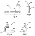
- the orthodontic attachment device 20a that is illustrated in Figs. 4 and 5 includes a connector 24a that is identical to the connector 24.
- the device 20a also includes a wire 22a that is identical to the wire 22, except that the distal end portion of the wire 22a has a straight configuration.
- the device 20a also includes a coupler 60a having a first passage 62a and a second passage 64a.
- the coupler 60a also includes a body 66a that, in this embodiment, is a generally "C"-shaped section of relatively stiff wire.
- An example of a suitable wire is 0.034 inch (0.76mm) diameter stainless steel wire having a circular transverse cross-sectional configuration.
- the first passage 62a is located in a tubular member 68a that is brazed to a distal end portion of the body 66a.
- the second passage 64a is located within a member 70a that is brazed to a mesial end portion of the body 66a.
- the member 70a has deformable wall portions similar to the wall portions 28 that may be moved inwardly toward each other under the influence of pliers or another tool in order to securely grasp an archwire.
- Figure 8 is an illustration for exemplary purposes of the attachment device 20a when used in connection with the coupler 60a for a patient undergoing orthodontic treatment.
- elements denoted with numerals lacking the "a" designation are the same as like-numbered elements described above in connection with Fig. 3, and as such a detailed description of those elements need not be repeated.
- the member 70a of the coupler 60a is crimped onto the lower archwire 46 at a location near the mesial side of a lower buccal tube 54a.
- the distal end portion of the wire 22a is inserted into the first passage 62a of the coupler 60a after being cut as needed to the proper length.
- the connector 24a is crimped onto the lower archwire 46 at a location between the patient's lower right cuspid and first bicuspid tooth.
- both the first passage 62a and the transverse cross-sectional configuration of the distal end portion of the wire 22a are circular and hence might otherwise be swivelable relative to each other, the crimped connector 24a and the crimped member 70a essentially preclude swiveling movement of the device 20a including the coupler 60a about the longitudinal axis of the lower archwire 46. Consequently, the device 20a serves as a fixed, secure connection that slidably couples the lower end of the appliance 36 to the patient's lower jaw 42.
- the buccal tube 54a may differ from the buccal tube 54 in that the buccal tube 54a may have only a single passage for receiving the lower archwire 46 and may lack an auxiliary passage such as might also be used for lip bumpers or the like. Consequently, by use of the coupler 60a, the orthodontist need not replace the lower buccal tube 54a with another buccal tube having an auxiliary passage when use of a correction appliance such as appliance 36 is desired.
- a coupler 60b includes a member 68b with a first passage 62b and a member 70b with a second passage 64b.
- the members 68b, 70b are identical to the members 68a, 70a respectively and thus a detailed description of both need not be repeated.
- the coupler 60b also includes a body 66b that in this embodiment is made of the same material as the body 66a and is connected to the members 68b, 70b in a manner similar to the manner of connection of the body 66a to the members 68a, 70a.
- the body 66b has an offset, or generally "Z"-shaped configuration as can be best appreciated by reference to Fig. 9.
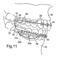
- Figure 11 is an illustration for exemplary purposes of the coupler 60b when used in place of the coupler 60a in conjunction with other elements of the attachment device 20a shown in Figs. 4 and 5.
- numerals that are the same as numerals in Figs. 4-5 and 8 refer to identical elements, and as such a detailed description of those elements need not be repeated.
- the coupler 60b is connected to the lower archwire 46 in a manner similar to that described in connection with the coupler 60a in Fig. 8.
- the distal end portion of the attachment device 20a is connected to the coupler 60b in Fig. 11 in a manner identical to the attachment of the same distal end portion to the coupler 60a.
- the generally "Z"-shaped configuration of the body 66b provides an advantage in that under some circumstances the lower end of the appliance 36 may move further in a distal direction when the jaws 40, 42 are opened in comparison to the possible range of travel of the lower end of the appliance 36 in the embodiment shown in Fig. 8.
- FIGs. 12 and 13 Another embodiment of the invention is illustrated in Figs. 12 and 13, and concerns a coupler 60c having a member 68c with a first passage 62c and a member 70c with a second passage 64c.
- the members 68c, 70c are identical to the members 68a, 70a.
- the coupler 60c includes a body 66c that is somewhat different than the body 66a or body 66b.
- the body 66c is a generally "S"-shaped bar section of metallic stock such as type 304 stainless steel.
- the members 68c, 70c are brazed to the body 66c.
- the body 66c may be cut and formed from initially flat stock by a stamping operation.
- the embodiment of the invention that is shown in Figs. 14 and 15 concerns a coupler 60d made of a unitary section of metallic material.
- the coupler 60d may be made by a casting, machining or metal injection molding process.
- the coupler 60d includes member portion 68d having a first passage 62d that is similar to the passage 62a and a member portion 70d having a second passage 64d that is similar to the second passage 64a.
- Wall portions of the coupler 60d surrounding the second passage 64d are deformable in an inwardly direction toward each other. As a consequence, the wall portions can be crimped into an orientation of secure, non-rotatable connection to an archwire such as the lower archwire 46.
- FIG. 16-18 Another aspect of the invention, which is especially useful in combination with the attachment device 20, 20a and the appliance 36, is an orthodontic pin 76 that is illustrated in Figs. 16-18.
- the pin 76 alone is shown in Fig. 16, and includes an elongated shank 78 having a first section 80 for rotatable reception within a passage of a buccal tube secured to a patient's tooth.
- the shank 78 also includes a second section 82 remote from the first section 80.
- the pin 76 has an enlarged generally spherical head 84 secured to the distal end of the second section 82.
- the head 84 is integrally connected to the shank 78, and the pin 76 is made of a non-corrosive non- toxic material such as 300 series stainless steel.
- the pin 76 may be made by a casting, machining, cold-heading or metal injection molding process.
- the second section 82 of the pin 76 is offset from the first section 80.
- the second section 82 extends along an axis that is parallel to but offset from the longitudinal axis of the first section 80.
- the second section 82 is connected to the first section 80 by an intermediate section 86 that extends along an axis that is preferably oriented 90° or less relative to the longitudinal axes of the first section 80 and the second section 82 respectively.
- the shank 78 is made of a wire section having a diameter of approximately 0.04 inch (1mm).
- an outermost end region of the first section 80 has a reduced cross-sectional area that is smaller in area than remaining transverse cross-sectional areas of the shank 78, so that the end region can be readily bent by the orthodontist as needed after insertion of the first section 80 into an appliance.
- Figs. 17 and 18 the pin 76 is shown for exemplary purposes as it might be used for a patient undergoing orthodontic treatment.
- numerals that are the same as the numerals shown in Fig. 11 refer to identical elements, and as such a detailed description of those elements need not be repeated.
- buccal tube shall mean any appliance that is secured to a molar tooth of the patient.
- installation of the pin 76 is carried out by threading the shank 78 through the upper opening of the appliance 36 and then inserting the first section 80 of the shank 78 into an auxiliary passage of the upper buccal tube 48.
- the outermost end region of the first section 80 is bent in an arc by a pliers or other tool, until such time as such outer end region extends at an angle of approximately 90° relative to the longitudinal axis of remaining portions of the first section 80.
- the bent outer end region serves to retain the pin 76 in the buccal tube 48 and the intermediate section 86 serves as a stop to limit longitudinal sliding movement of the pin 76 relative to the buccal tube 48.
- the shank 78 tends to move toward the orientation shown in Fig. 17 wherein the second section 82 is located upwardly of the first section 80 and is essentially as remote as possible from the lower dental arch 42.
- the upper end of the appliance 36 bears against the head 84 while the lower end of the appliance 36 bears against the bottom of the mesial end portion of the wire 22 that is closest to the center of the patient's lower dental arch 42.
- the additional space may greatly reduce tensile stresses on the pin 76, the upper buccal tube 48, the device 20a, the lower archwire 46 and the brackets 38 in the vicinity of the attachment device 20a, such that the likelihood of breakage of such elements and debonding of such brackets 38 from the associated teeth is greatly reduced.
- a pin 90 that is shown in Fig. 19 is an alternative embodiment of the pin 76 described above.
- the pin 90 includes an elongated shank 92 with a first section 91 and a second section 93.
- An enlarged spherical head 94 is preferably integrally connected to the shank 92.
- the head 94 and the shank 92 are preferably constructed of the materials set out above in connection with the pin 76.
- the pin 90 also includes a ball stop 96 that is fixedly secured to the shank 92 at a location between the first section 91 and the second section 93 by a crimping operation.
- the shank 92 is threaded through the opening in the upper portion of an appliance such as the appliance 36 described above.
- the ball stop 92 is spaced from the head 94 a distance in the range of about 2 mm to about 5 mm, and the upper end of the appliance 36 is freely slidable on the second section 93 of the shank 92.
- the first section 91 is initially straight, and is bent by the orthodontist after insertion into the buccal tube 48.
- the ball stop 96 limits the range of sliding movement of the shank 92 in the buccal tube 48, while also enabling the appliance 36 to slide along the second section 93 without hindrance as may occur, for example, when the patient's jaws are opened and closed.
- the stop 96 shown in the drawings has a generally spherical configuration, it should be understood that other types of stops are also possible so long as the stop is effective in limiting sliding movement of the pin and also enables the appliance (such as appliance 36) to slide along a portion of the shank of the pin.
- the stop could be integral or initially separate from the shank.
- Fig. 20 shows the pin 90 in an orientation where the shank 92 has been bent such that the longitudinal axis of the second section 93 extends at an acute angle relative to the longitudinal axis of the portion of the first section 91 that is within the buccal tube 48.
- the pin 90 can swivel within the buccal tube 48 about the longitudinal axis of the first section 91 in a manner similar to swiveling movement of the shank 78 as discussed above.
- Such swiveling motion provides additional space for movement of the appliance 36 so that the likelihood of imposing undue tensile stresses on the pin 90, the buccal tube 48 and other components is significantly reduced.
- shank configurations are also possible, such as the offset configuration illustrated in Figs. 16-18.
- attachment device 20, 20a and the pin 76 may be used in other applications or with appliances (such as Herbst, Class III correction devices, intra-arch devices and other appliances) other than the appliance 36.
- appliances such as Herbst, Class III correction devices, intra-arch devices and other appliances
Landscapes
- Health & Medical Sciences (AREA)
- Oral & Maxillofacial Surgery (AREA)
- Dentistry (AREA)
- Epidemiology (AREA)
- Life Sciences & Earth Sciences (AREA)
- Animal Behavior & Ethology (AREA)
- General Health & Medical Sciences (AREA)
- Public Health (AREA)
- Veterinary Medicine (AREA)
- Dental Tools And Instruments Or Auxiliary Dental Instruments (AREA)
Applications Claiming Priority (2)
| Application Number | Priority Date | Filing Date | Title |
|---|---|---|---|
| US08/635,079 US5718576A (en) | 1996-04-19 | 1996-04-19 | Orthodontic attachment device and pin |
| US635079 | 1996-04-19 |
Publications (2)
| Publication Number | Publication Date |
|---|---|
| EP0801931A2 true EP0801931A2 (fr) | 1997-10-22 |
| EP0801931A3 EP0801931A3 (fr) | 1999-02-17 |
Family
ID=24546361
Family Applications (1)
| Application Number | Title | Priority Date | Filing Date |
|---|---|---|---|
| EP97106463A Withdrawn EP0801931A3 (fr) | 1996-04-19 | 1997-04-18 | Dispositif d'ancrage orthodontique et cheville |
Country Status (3)
| Country | Link |
|---|---|
| US (1) | US5718576A (fr) |
| EP (1) | EP0801931A3 (fr) |
| JP (1) | JPH1033561A (fr) |
Cited By (3)
| Publication number | Priority date | Publication date | Assignee | Title |
|---|---|---|---|---|
| WO2003011166A1 (fr) * | 2001-07-25 | 2003-02-13 | 3M Innovative Properties Company | Dispositif de fixation d'un appareil orthodontique intra-buccal |
| WO2004098441A1 (fr) * | 2003-04-30 | 2004-11-18 | 3M Innovative Properties Company | Ensemble de repositionnement mandibulaire |
| CN108472104A (zh) * | 2016-01-04 | 2018-08-31 | 3M创新有限公司 | 用于正畸iii类矫正的连杆式连接 |
Families Citing this family (21)
| Publication number | Priority date | Publication date | Assignee | Title |
|---|---|---|---|---|
| US5964588A (en) * | 1998-04-21 | 1999-10-12 | 3M Innovative Properties Company | Telescoping, intra-oral force module |
| US5980247A (en) | 1998-04-21 | 1999-11-09 | 3M Innovative Properties Company | Mandibular repositioning device |
| US6234791B1 (en) | 1998-11-20 | 2001-05-22 | 3M Innovative Properties Company | Orthodontic coupling pin |
| US6120289A (en) * | 1999-03-24 | 2000-09-19 | 3M Innovative Properties Company | Orthodontic attachment device for interarch appliances |
| US6053730A (en) * | 1999-07-28 | 2000-04-25 | 3M Innovative Properties Company | Orthodontic force module with fracture-resistant coupling |
| JP3956613B2 (ja) * | 2000-12-08 | 2007-08-08 | 株式会社古河テクノマテリアル | NiTiCu形状記憶合金通電アクチュエータ素子 |
| US6669474B2 (en) * | 2001-05-02 | 2003-12-30 | William Vogt | Anti-rotational interarch orthodontic device |
| US20020196336A1 (en) * | 2001-06-19 | 2002-12-26 | Applied Materials, Inc. | Method and apparatus for substrate imaging |
| US7070410B2 (en) * | 2004-09-02 | 2006-07-04 | Cacchiotti Dino A | Orthodontic device for attachment to orthodontic wire |
| US20060263737A1 (en) * | 2005-05-20 | 2006-11-23 | Ormco Corporation | Orthodontic brackets and appliances and methods of making and using orthodontic brackets |
| KR100849457B1 (ko) | 2007-02-08 | 2008-07-30 | (주)덴토스 | 치열교정용 탄성체 훅 지지구 |
| KR100899535B1 (ko) * | 2007-08-09 | 2009-05-26 | 이준호 | 브래킷 또는 튜브용 이송 지그, 이의 제작법 및 사용법 |
| EP2419042A1 (fr) * | 2009-04-14 | 2012-02-22 | 3M Innovative Properties Company | Connecteur orthodontique permettant une mise en prise régulée avec un fil orthodontique |
| US8257080B2 (en) * | 2009-05-05 | 2012-09-04 | 3M Innovative Properties Company | Low profile orthodontic bite corrector |
| US8376741B2 (en) * | 2009-05-20 | 2013-02-19 | Ultimate Wireforms, Inc. | Handle for crimpable orthodontic archwire stop, archwire assembly and method of using |
| US9101437B2 (en) * | 2013-02-26 | 2015-08-11 | T. Richard Ziehmer | Mandibular attachment for correction of malocclusion |
| US9402696B2 (en) | 2013-03-14 | 2016-08-02 | Ultradent Products, Inc. | Pin connector for orthodontic force module |
| EP2881076B1 (fr) * | 2013-12-06 | 2019-07-31 | 3M Innovative Properties Company | Dispositif d'attachement labial destiné à être utilisé avec un système orthodontique auxiliaire et un système orthodontique lingual |
| JP6522879B2 (ja) * | 2014-02-28 | 2019-05-29 | 長谷川 エリナ | 顎位矯正装置 |
| WO2017037689A1 (fr) * | 2015-09-01 | 2017-03-09 | Wool Suzanne | Boucle de rétraction sertissable |
| JP6557637B2 (ja) * | 2016-07-06 | 2019-08-07 | 株式会社Nn | 歯科用矯正器具 |
Family Cites Families (24)
| Publication number | Priority date | Publication date | Assignee | Title |
|---|---|---|---|---|
| US741687A (en) * | 1903-03-14 | 1903-10-20 | James N Macdowell | Tooth-regulating apparatus. |
| US1014029A (en) * | 1911-08-18 | 1912-01-09 | Edward H Angle | Dental tooth-regulating appliance. |
| US2959856A (en) * | 1959-09-15 | 1960-11-15 | Orthodontic Specialties Inc | Orthodontic device |
| US3158934A (en) * | 1961-02-21 | 1964-12-01 | Waldman David | Orthodontic appliances |
| US3137941A (en) * | 1961-05-31 | 1964-06-23 | Lawrence F Andrews | Extra-oral dental retractor |
| US3121953A (en) * | 1962-08-30 | 1964-02-25 | Pages Inc | Orthodontic appliance and method |
| US3238619A (en) * | 1963-04-29 | 1966-03-08 | Rocky Mouutain Dental Products | Arch wire locking device for orthodontic bracket |
| US3315359A (en) * | 1965-03-01 | 1967-04-25 | Clifford E Moss | Orthodontic device |
| US3798773A (en) * | 1972-05-08 | 1974-03-26 | M Northcutt | Device for improving the alignment of the upper and lower sets of teeth with each other |
| US3936938A (en) * | 1974-05-17 | 1976-02-10 | Aledyne Corporation | Orthodontic spring appliance and spring clip therefor |
| US3997970A (en) * | 1975-10-06 | 1976-12-21 | Hodgson Edward W | Orthodontic occlusion-improving appliance |
| US4038754A (en) * | 1976-02-27 | 1977-08-02 | Northwest Orthodontics, Inc. | Orthodontic appliance guard |
| US4224021A (en) * | 1978-08-04 | 1980-09-23 | David Foxman | Adjustable attachment for a labial arch retainer |
| US4439148A (en) * | 1982-02-18 | 1984-03-27 | Haas Andrew J | Orthodontic appliances and method of treatment |
| US4462800A (en) * | 1982-11-04 | 1984-07-31 | Marston Jones | Orthodontic bite jumping device |
| US4525143A (en) * | 1983-12-21 | 1985-06-25 | Adams Richard M | Orthodontic device to serve as removable anchorage for elastic traction between upper and lower molars |
| US4583944A (en) * | 1985-01-10 | 1986-04-22 | Augusta Developments Inc. | Orthodontic devices |
| US4551095A (en) * | 1985-01-30 | 1985-11-05 | Mason Charles W | Attachment of Herbst mechanism to maxillary arch |
| US4708646A (en) * | 1986-04-01 | 1987-11-24 | Jasper James J | Orthodontic device for correcting the bite |
| US4849032A (en) * | 1987-03-18 | 1989-07-18 | Tomy, Inc. | Orthodontic coil spring and method of making the same |
| US5306142A (en) * | 1992-08-07 | 1994-04-26 | Tp Orthodontics, Inc. | Crimpable orthodontic hook |
| US5352116A (en) * | 1993-12-06 | 1994-10-04 | West Richard P | Adjustable bite corrector |
| US5435721A (en) * | 1994-02-15 | 1995-07-25 | Vogt; William | Orthodontic device |
| US5562445A (en) * | 1995-06-22 | 1996-10-08 | John Devincenzo | Resiliently expandable orthodontic device |
-
1996
- 1996-04-19 US US08/635,079 patent/US5718576A/en not_active Expired - Lifetime
-
1997
- 1997-03-27 JP JP7563797A patent/JPH1033561A/ja active Pending
- 1997-04-18 EP EP97106463A patent/EP0801931A3/fr not_active Withdrawn
Cited By (4)
| Publication number | Priority date | Publication date | Assignee | Title |
|---|---|---|---|---|
| WO2003011166A1 (fr) * | 2001-07-25 | 2003-02-13 | 3M Innovative Properties Company | Dispositif de fixation d'un appareil orthodontique intra-buccal |
| WO2004098441A1 (fr) * | 2003-04-30 | 2004-11-18 | 3M Innovative Properties Company | Ensemble de repositionnement mandibulaire |
| CN108472104A (zh) * | 2016-01-04 | 2018-08-31 | 3M创新有限公司 | 用于正畸iii类矫正的连杆式连接 |
| CN108472104B (zh) * | 2016-01-04 | 2021-04-20 | 3M创新有限公司 | 用于正畸iii类矫正的连杆式连接装置 |
Also Published As
| Publication number | Publication date |
|---|---|
| JPH1033561A (ja) | 1998-02-10 |
| US5718576A (en) | 1998-02-17 |
| EP0801931A3 (fr) | 1999-02-17 |
Similar Documents
| Publication | Publication Date | Title |
|---|---|---|
| US5718576A (en) | Orthodontic attachment device and pin | |
| US5651672A (en) | Orthodontic force module | |
| EP1073379B1 (fr) | Module de force intrabuccal telescopique | |
| EP1458303B1 (fr) | Procede et dispositif de liberation d'un arc dentaire d'un appareil orthodontique | |
| US6558160B2 (en) | Attachment device for intra-oral orthodontic appliance | |
| US6053730A (en) | Orthodontic force module with fracture-resistant coupling | |
| US5906486A (en) | Self-ligating orthodontic brackets | |
| EP1162924B1 (fr) | Dispositif d'attache orthodontique pour appareils interarcades | |
| US9498304B2 (en) | Orthodontic attachment module for intra-oral bite correctors | |
| US5980247A (en) | Mandibular repositioning device | |
| JP4405917B2 (ja) | 歯科矯正アセンブリ用連結器 | |
| US5624258A (en) | Orthodontic arch wire and appliance employing the same | |
| EP2419043A1 (fr) | Module de force interarcades avec liaison pour traitement orthodontique | |
| US20020132207A1 (en) | Orthodontic device for treatment of malocclusion | |
| US6234791B1 (en) | Orthodontic coupling pin |
Legal Events
| Date | Code | Title | Description |
|---|---|---|---|
| PUAI | Public reference made under article 153(3) epc to a published international application that has entered the european phase |
Free format text: ORIGINAL CODE: 0009012 |
|
| AK | Designated contracting states |
Kind code of ref document: A2 Designated state(s): DE FR GB IT |
|
| PUAL | Search report despatched |
Free format text: ORIGINAL CODE: 0009013 |
|
| AK | Designated contracting states |
Kind code of ref document: A3 Designated state(s): DE FR GB IT |
|
| 17P | Request for examination filed |
Effective date: 19990812 |
|
| 17Q | First examination report despatched |
Effective date: 20011213 |
|
| RTI1 | Title (correction) |
Free format text: ORTHODONTIC PIN |
|
| GRAH | Despatch of communication of intention to grant a patent |
Free format text: ORIGINAL CODE: EPIDOS IGRA |
|
| STAA | Information on the status of an ep patent application or granted ep patent |
Free format text: STATUS: THE APPLICATION IS DEEMED TO BE WITHDRAWN |
|
| 18D | Application deemed to be withdrawn |
Effective date: 20030128 |