EP0801534B1 - Optische darstellung des blutkreislaufs und von abnormalen gefässstrukturen in der aderhaut des auges - Google Patents
Optische darstellung des blutkreislaufs und von abnormalen gefässstrukturen in der aderhaut des auges Download PDFInfo
- Publication number
- EP0801534B1 EP0801534B1 EP94931769A EP94931769A EP0801534B1 EP 0801534 B1 EP0801534 B1 EP 0801534B1 EP 94931769 A EP94931769 A EP 94931769A EP 94931769 A EP94931769 A EP 94931769A EP 0801534 B1 EP0801534 B1 EP 0801534B1
- Authority
- EP
- European Patent Office
- Prior art keywords
- dye
- fluorescence
- icg
- cnv
- choriocapillaris
- Prior art date
- Legal status (The legal status is an assumption and is not a legal conclusion. Google has not performed a legal analysis and makes no representation as to the accuracy of the status listed.)
- Expired - Lifetime
Links
- 0 **C1CCCC1 Chemical compound **C1CCCC1 0.000 description 1
- IFTRQJLVEBNKJK-UHFFFAOYSA-N CCC1CCCC1 Chemical compound CCC1CCCC1 IFTRQJLVEBNKJK-UHFFFAOYSA-N 0.000 description 1
Images


Definitions
- the invention relates to a method for improving the visualization of choroidal neovascularization (CNV) during angiography by injecting intravenously a fluorescent dye, the dye filling the vasculature of an eye; exciting the dye thereby causing a fluorescence to be emitted from the vasculature; and taking an angiographic image of the fluorescence from the CNV.
- a device for bringing about such improved visualization comprising a fundus camera; an excitation light source coupled to the fundus camera; and a means for receiving images from the fundus camera.
- capillary plexuses In general, it has to be emphasized that there is very little information about the blood flow through capillary plexuses which occurs on the time scale of the cardiac cycle. In part this is because direct visualization of such plexuses usually is technologically difficult or impossible, and most blood flow measurement methodologies require that data be obtained over many cardiac cycles. Moreover, when the capillary plexuses have complex vascular geometries and are fed by many arterioles, the additional problem of sorting-out blood flow distributions arises.
- a capillary plexus is that found in the cerebral cortex.
- Another example, of great interest to scientists studying the eye is the choriocapillaris, one of three blood vessel layers of the choroid.
- the choroidal circulation of the eye bears a major responsibility for maintaining the sensory retina which lies above it.
- a prior art method has made possible routine visualization of the entire choroidal circulation, that is, all three vessel layers of the choroid can be visualized, superimposed one above the other.
- the innermost layer, the choriocapillaris constitutes all of the nutritive vessels (i.e., where metabolic exchange with the retina takes place) for the choroidal circulation.
- the choriocapillaris layer occupies the plane immediately adjacent to the sensory retina.
- choroidal angiograms show all of the vessels of the choroid, information pertaining specifically to the choriocapillaris is the most important, and there are conflicting views about the organization of the posterior pole choriocapillaris, particularly concerning blood flow through it.
- the method of extracting information about the choriocapillaris from an indocyanine green (ICG) angiogram is therefore an important one to the clinician who is interested in evaluating the metabolic sufficiency and stability of the choroidal circulation.
- ICG indocyanine green
- ICG angiography High-speed indocyanine green (ICG) dye fluorescence angiography was developed to overcome the major problems encountered when attempting to visualize the rapid choroidal blood flow encountered in sodium fluorescein angiography.
- ICG angiography utilizes near-infrared wavelengths which penetrate the retinal pigment epithelium and choroidal pigment with relative ease.
- fluorescence from the choriocapillaris resulting from intravenously injected sodium fluorescein dye (the other standard dye used in ocular angiography) appears to arise mainly from extravasated dye molecules or those adhering to the vessel walls
- ICG fluorescence arises from dye molecules bound to blood protein in the moving blood volume.
- ICG angiography provides the best temporal and spatial resolution, making visualization of dye passage through the choroid possible under normal physiological conditions (i.e., without having to artificially slow blood flow by such methods as raising intraocular pressure).
- lobule is a term used to denote the three- to six-sided vascular units which form a mosaic pattern throughout the choriocapillaris.
- Each lobule consists of a cluster of narrow, tightly meshed capillaries which appear to radiate from a central focus at which a feeding arteriole enters at the posterior wall of the capillaries.
- ICG fluorescence angiograms of the choroidal circulation can delineate aberrant vascular structures in the choroid which significantly diminish vision.
- Age-Related Macular Degeneration is the leading cause of significant visual impairment in the elderly. This disease is frequently characterized by development of choroidal neovascularization (CNV) membranes which invade the sub-retinal space, resulting in displacement of the sensory retina, and often blocking of the visual pathway as a result of subsequent hemorrhage.
- CNV choroidal neovascularization
- Treatment of ARMD is primarily by laser photocoagulation of the neovascular membrane. This treatment, however, is successful to the extent that the membrane can be accurately mapped; this is because such membranes are (by definition) in the macular area and often encroach on the fovea. Inappropriate application of photocoagulation can easily result in destruction of high acuity vision, and/or in accelerated growth of the CNV.
- angiograms both fluorescein and ICG.
- angiograms both fluorescein and ICG.
- the morphology of CNV lesions is such that the membranes appear in fluorescein angiograms as little more than fuzzy blurs, if at all, especially when the membrane lies beneath a serous detachment.
- ICG angiograms provide necessary treatment data which sodium fluorescein angiograms cannot.
- a further major difficulty in utilizing ICG angiograms when applying laser photocoagulation therapy is that the retinal vascular landmarks upon which the surgeon must depend when aiming the laser are often missing from the ICG angiograms.
- the usual approach to resolving this problem is to make, during a separate setting, color photographs of the fundus and sodium fluorescein angiograms of the same eye of the patient; it is then necessary to attempt to superimpose the choroidal ICG angiogram and the retinal photograph or retinal fluorescein angiogram.
- This technique often fails due to the inability to precisely align the eye in exactly the same manner during each of the two angiographic procedures. Nevertheless, very accurate alignment (within as little as 50 microns on the retina) is vital to safely apply laser photocoagulation near the fovea and, at the same time, assure no significant permanent damage to the fovea itself.
- a method of visualisation of CNV (not claimed) is based on the premises that dye-filling of the choriocapillaris is more rapid --being pulsatile-- than dye-filling of the underlying larger diameter vessels and that fluorescence from these two overlapping layers is additive.
- the premise regarding the velocity of blood in the choriocapillaris runs contrary to conventional wisdom regarding the relationship between blood velocities in parent and daughter vessels in most vascular beds.
- the idea consists of recognizing that pixel-by-pixel subtraction of an image from a succeeding image in an ICG angiographic sequence of choroidal images forms a resultant image sequence which shows fluorescence arising only from structures where the most rapid movement of blood occurs, i.e., in the choriocapillaris and CNV vessels.
- This subtraction enhancement method makes it possible to extract information about choriocapillaris dye filling by taking advantage of the differences in large vessel and choriocapillaris blood flow rates which naturally exist. Instead of distinguishing choroidal layers by temporal sequence of dye bolus appearance, it is dye filling rates which serve to separate them.
- Implementation of the present method depends only upon configuring an existing fundus camera system to have sufficient temporal resolution and magnification of fundus structure.
- the described method was applied to high-speed ICG fluorescence angiograms to emphasize information about choriocapillaris hemodynamics.
- the invention consists of a modified fundus camera with a polarizing filter in front of the excitation light source and an analyzing polarizer in front of the video camera.
- ICG dye fluorescence emanating from the fundus of the eye includes a significant component of polarized light, and rotation of the analyzer filter results in unwanted fluorescence (i.e., that not associated with vascular structures, but rather associated with scattered light) being suppressed to the extent that the underlying CNV can be better visualized.
- This particular process affects the unprocessed, raw angiographic images in that it improves the signal-to-noise content of the individual angiographic images; subsequently, the subtracted raw images result in a clearer resultant image.
- the present invention resides in providing the visualization method of the type comprising the steps set out in the initial paragraph of this specification by suppressing fluorescence other that fluorescence from the CNV using a polarizing filter in front of the excitation light source and an analyzing polarizer placed in a fundus camera when taking the angiographic image.
- the present invention also provides for a device for improving the visualization of CNV comprising a structure of the type also explained in said initial paragraph of this specification by placing a polarizing filter in front of the light source and an analysing polariser between the receiving means and the fundus camera, with the receiving means optionally comprising a video camera.
- the present method may further rely on the usual practice of performing fluorescein angiography prior to performing ICG angiography and makes use of the fact that the fluorescein dye remains associated with the retinal vasculature for more than one hour.
- an ICG fundus camera which has an integrating sphere coupled to light sources for excitation of both ICG and sodium fluorescein dye fluorescences and which uses a gated charge-coupled device (CCD) video camera to capture the angiographic images.
- Light input to the integrating sphere is via two fiber optic cables, each connected to one of two light sources.
- One source is laser output at the wavelength needed to excite sodium fluorescein dye (480nm, i.e., a frequency-doubled Nd-Yag); it is also recognized that a shuttered, filtered incandescent light source can be used in place of a frequency-doubled laser.
- the other source is a diode laser output for excitation of ICG dye (805nm).
- the gated video camera records images of the ICG dye by causing the 805nm laser diode to fire in synchrony with the video camera.
- Appropriate programming of the camera and light sources are configured such that at regular intervals (e.g., every eighth image) the 480nm light source is fired and, simultaneously, an appropriate change is made in the barrier filter in front of the video camera.
- a barrier filter change is implemented simply by placing a rotating disk containing eight filters in front of the video camera. This filter wheel turns in synchrony with the camera firings such that every eighth frame corresponds to a positioning of the sodium fluorescein barrier filter in front of the camera. Because the sequence of angiograms is made at high speeds (approximately 15-30 images/second), eye movements between successive images is insignificant, making precise registration of images trivial. Thus, the method provides the ability to precisely superimpose the retinal vessel landmarks contained in sodium fluorescein angiograms on the delineated CNV lesions in the ICG angiograms, as needed by the surgeon to accurately focus a laser for treatment.
- the invention is based on the premises that the fluorescence intensities of ICG-filled choriocapillaris and underlying vessels are additive and that there are detectable differences in the rates of change of fluorescence intensities emanating from the choriocapillaries and the underlying choroidal vessels as they fill with dye.
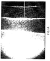
- ICG fluorescence additivity was demonstrated by creating a stair-step wedge of overlapping thin layers of heparinized blood containing ICG dye (0.03 mg/ml); each step was formed by a thin layer of the blood sandwiched between two microscope slide coverglasses.
- Fig. 1a shows an ICG fluorescence image of the stair steps.
- the horizontal white line through the center of the image indicates the path along which image pixel brightness (i.e., grey level) was measured to produce the graph in Fig. 1b, demonstrating stepwise increase in fluorescence as the number of overlapping blood layers increased.
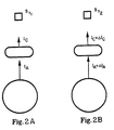
- Figs. 2a and 2b The greater rate of change in dye fluorescence intensity in choriocapillaries than in the larger underlying vessels is shown schematically in Figs. 2a and 2b.
- Fig. 2a the brightness of a large diameter vessel and an overlying choriocapillaris vessel (both in cross-section) are indicated as vectors, I A and I C , respectively.
- the fluorescent light emitted by both is detected at time t 1 by a light sensor, S.
- Fig. 2b the status of the same two vessels and sensor is shown at later time t 2 , where ⁇ I A and ⁇ I C are respectively the incremental increases in brightness of the two vessels.
- the small change in the combined brightness of the overlapping capillary and large vessel which occurs during a short time interval is virtually all attributable to the choriocapillaris vessel.
- This phenomenon can be demonstrated by the method of the invention, i.e., by subtracting, pixel for pixel, an image in a high-speed ICG fluorescence angiogram sequence from a succeeding image, as demonstrated in Figs. 3a-d.
- Figs. 3a and 3b are angiographic images made 1/15 second apart.
- Fig. 3c is the result of subtracting those two images, and Fig. 3d is simply an enlargement of Fig. 3c.
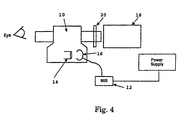
- the usual fundus camera 10 was modified by replacing the xenon flash tube light source with an 805 nm wavelength laser diode 12 coupled to the fundus camera's illumination optics 14 via a small integrating sphere 16 whose exit port was located at the position normally occupied by the flash tube arc.
- the fundus camera's usual means for receiving images i.e., the photographic film camera, was replaced with an infrared sensitive vidicon tube (model 4532URI Ultracon, Burle Industries) 18 (a charge-coupled device could be used instead of the vidicon tube), in front of which an 807 nm wavelength cut-on filter 20 was placed to exclude the excitation laser light while admitting ICG dye fluorescence light.
- Choroidal dye transit was recorded in thirty-two consecutive video angiographic images at a rate of 30 or 15 frames per second by two digital frame grabbers (model 2861-60, Data Translation) (not shown) installed in a personal computer (Compaq, model 386/25e) (not shown).
- Fig. 5 summarizes the angiographic findings obtained in the above test by applying the image subtraction method of the invention.
- each image in a 15 frames/second ICG angiographic sequence was subtracted from the image immediately following it; the images in Fig. 5 were selected from the resulting sequence of subtracted images.
- Dye first enters the macular area of the choriocapillaris which lies temporal to and above the points at which the short posterior ciliary arteries enter the eye (Fig. 5a).
- a lobular pattern can be seen in the center of the angiogram, particularly just nasal to the center; here a cluster of unfilled lobules is shown (arrows). 0.133 seconds later (Fig. 5b) the entire central area is completely filled, although two smaller clusters of late-filling lobules may be seen superior to the center (arrows).
- Choriocapillaris filling progresses almost radially from the macular region. By close inspection of this image, faint loss of fluorescence around lobules can be seen; these likely correspond to choriocapillaris drainage channels.
- Fig. 5c is 0.200 seconds later than Fig. 5b. It indicates that the radially oriented wave of choriocapillaris dye filling has been completed, and dye distribution at the posterior pole region appears fairly uniform. This image indicates that the first wave of dye filling is complete within the center of the macular region, as indicated by the appearance of relatively hypo-fluorescent areas which were hyper-fluorescent in Fig. 5a.
- Fig. 5d 0.133 seconds later, it appears that the first wavefront of dye filling has reached the peripheral region; at this stage, Fig. 5d is nearly a complete reverse contrast image of Fig. 5a.
- the wavefront of dye filling traveled radially from the macular region to the periphery of the 30 degree field of view in approximately 0.466 seconds. This overall filling pattern was present in each eye observed, and details of the filling patterns were remarkably consistent from observation to observation for each subject eye.
- ICG fluorescence angiography gradually is being used more frequently by both researchers and clinicians to investigate the choroidal circulation.
- new tools are applied in a variety of new ways to studying the choroid, old concepts about it and its physiology will be revisited, and some will change or give way to entirely new concepts.
- some approaches to analyzing choroidal angiograms like the subtraction method described above may be applied both in animal and in human clinical research with complete safety, perhaps hastening a better understanding of choroidal blood flow in health and disease.
- ICG fluorescence angiography is used in the diagnosis and treatment of ARMD; however, as noted above, the difficulty arises in attempting to accurately map choroidal neovascularization (CNV).
- CNV choroidal neovascularization
- the dye in the vasculature of an eye containing CNV, the dye may bind with greater affinity to neovascular endothelium than to established endothelium.
- fluorescence arising from those bound dye molecules may be substantially different from fluorescence associated with ICG dye molecules which may be bound to other types of protein in the cirrus fluid or from ICG fluorescent light simply scattered by the presence of protein molecules within the cirrus fluid.
- ellipsometry is an appropriate tool for improving the visualization of CNV.
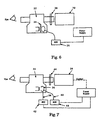
- the method then, as shown in Fig. 6, is a modified fundus camera 22 with a polarizing filter 24 in front of the excitation light source 26 and an analyzing polarizer 28 in front of the video camera 30.
- ICG dye produces a high degree of polarized light, and rotation of the analyzer filter results in the fluorescence from the serous fluid being suppressed to the extent that the underlying CNV can be better visualized.
- This particular process affects the unprocessed, raw angiographic images in that it improves the signal-to-noise content of the individual angiographic images; subsequently, the subtracted raw images result in a clearer resultant image.
- an aberrant vascular structure such as CNV can be treated using laser photocoagulation therapy; however, as noted above, aiming the laser properly requires superimposing an ICG angiogram and a retinal photograph or retinal fluorescein angiogram.
- the method results from the usual practice of performing fluorescein angiography prior to performing ICG angiography making use of the fact that the fluorescein dye remains associated with the retinal vasculature for quite long periods of time (more than one hour).
- the device utilizes an ICG fundus camera 32 which has an integrating sphere 34 coupled to light sources for excitation of ICG dye fluorescence and which uses, as an image receiving means, a gated video camera 36 (preferably CCD) to capture the angiographic images.
- Light input to the integrating sphere is via two fiber optic cables 38, 40, each connected to one of two light sources 42, 44; one source 42 output is at the wavelength needed to excite sodium fluorescein dye (480nm) and the other source 44 output for excitation of ICG dye (805nm).
- the gated video camera 36 records images of the ICG dye by causing the 805nm laser source 44 to fire in synchrony with the video camera 36.
- Appropriate programming of the camera and light sources are configured such that at regular intervals (e.g., every eighth image) the 480nm source 42 is fired, and simultaneously an appropriate change is made in the barrier filter 46 in front of the video camera.
- the barrier filter chain is implemented simply by placing a rotating disk containing eight filters in front of the video camera. This filter wheel turns in synchrony with the camera firings such that every eighth frame corresponds to a positioning of the fluorescein barrier filter in front of the camera.
- the device provides the ability to precisely superimpose angiograms needed by the surgeon in order to accurately aim a laser photocoagulation beam.
Claims (3)
- Ein Verfahren zum Verbessern der Sichtbarmachung chorioidaler Neovaskularisation (CNV) während der Angiographie, umfassend die Schritte:gekennzeichnet durchintravenöses Injizieren eines fluoreszenten Farbstoffes, wobei dieser Farbstoff die Gefäßanordnung (Vaskulatur) des Auges füllt;Anregen des Farbstoffes durch Licht von einer Lichtquelle, wodurch ein Ausstrahlen von Fluoreszenz aus der Gefäßanordnung hervorgerufen wird; undGewinnen eines angiographischen Bildes der Fluoreszenz von der CNV durch eine Funduskamera;Unterdrücken von Fluoreszenz außer der Fluoreszenz von der CNV unter Verwendung eines polarisierenden Filters vor der Lichtquelle und eines analysierenden Polarisators in der Funduskamera beim Aufnehmen des angiographischen Bildes.
- Eine Einrichtung zum Verbessern der Sichtbarmachung chorioidaler Neovaskularisation (CNV), umfassend:gekennzeichnet durcheine Funduskamera (22);eine Anregungslichtquelle (26), die mit der Funduskamera synchronisiert ist; undein Mittel (30) zum Empfangen von Bildern von der Funduskamera;ein Polarisationsfilter (24), das vor der Lichtquelle angeordnet ist; undeinen analysierenden Polarisator (28), der zwischen dem Empfangsmittel und der Funduskamera angeordnet ist.
- Die Einrichtung nach Anspruch 2, wobei das Empfangsmittel eine Videokamera (30) umfaßt.
Priority Applications (10)
| Application Number | Priority Date | Filing Date | Title |
|---|---|---|---|
| EP00250386A EP1084675B1 (de) | 1994-09-26 | 1994-09-26 | Verfahren und Vorrichtung zur Herstellung von Angiogrammen eines Auges |
| ES00250386T ES2251938T3 (es) | 1994-09-26 | 1994-09-26 | Metodo y dispositivo para proporcionar angiogramas de un ojo. |
| AT00250385T ATE229298T1 (de) | 1994-09-26 | 1994-09-26 | Verfahren und vorrichtung zum unterscheiden einer ersten lage von blutgefä en von einer zweiten |
| DK00250385T DK1084674T3 (da) | 1994-09-26 | 1994-09-26 | Fremgangsmåde til synlig skelnen af et første lag af blodkar fra et andet og indretning hertil |
| ES00250385T ES2188474T3 (es) | 1994-09-26 | 1994-09-26 | Metodo para la distincion visual de una primera capa de vasos sanguineos de una segunda capa y dispositivo para ello. |
| EP00250385A EP1084674B1 (de) | 1994-09-26 | 1994-09-26 | Verfahren und Vorrichtung zum Unterscheiden einer ersten Lage von Blutgefä en von einer zweiten |
| ES94931769T ES2210264T3 (es) | 1994-09-26 | 1994-09-26 | Visualizacion mejorada del flujo de sangre coroidal y de las estructuras vasculares aberrantes en el ojo. |
| DE69431890T DE69431890T2 (de) | 1994-09-26 | 1994-09-26 | Verfahren und Vorrichtung zum Unterscheiden einer ersten Lage von Blutgefä en von einer zweiten |
| HK01106694A HK1037311A1 (en) | 1994-09-26 | 2001-09-21 | Method and device for providing angiograms of an eye |
| HK01106695A HK1037312A1 (en) | 1994-09-26 | 2001-09-21 | Method of visibly distinguishing a first layer of blood vessels from a second one and device therefor |
Applications Claiming Priority (1)
| Application Number | Priority Date | Filing Date | Title |
|---|---|---|---|
| PCT/US1994/010877 WO1996009792A1 (en) | 1993-05-17 | 1994-09-26 | Improved visualization of choroidal blood flow and aberrant vascular structures in the eye |
Related Child Applications (2)
| Application Number | Title | Priority Date | Filing Date |
|---|---|---|---|
| EP00250386A Division EP1084675B1 (de) | 1994-09-26 | 1994-09-26 | Verfahren und Vorrichtung zur Herstellung von Angiogrammen eines Auges |
| EP00250385A Division EP1084674B1 (de) | 1994-09-26 | 1994-09-26 | Verfahren und Vorrichtung zum Unterscheiden einer ersten Lage von Blutgefä en von einer zweiten |
Publications (3)
| Publication Number | Publication Date |
|---|---|
| EP0801534A1 EP0801534A1 (de) | 1997-10-22 |
| EP0801534A4 EP0801534A4 (de) | 1998-08-26 |
| EP0801534B1 true EP0801534B1 (de) | 2003-12-10 |
Family
ID=22243038
Family Applications (1)
| Application Number | Title | Priority Date | Filing Date |
|---|---|---|---|
| EP94931769A Expired - Lifetime EP0801534B1 (de) | 1994-09-26 | 1994-09-26 | Optische darstellung des blutkreislaufs und von abnormalen gefässstrukturen in der aderhaut des auges |
Country Status (6)
| Country | Link |
|---|---|
| EP (1) | EP0801534B1 (de) |
| JP (1) | JP3310676B2 (de) |
| AT (1) | ATE255845T1 (de) |
| DE (1) | DE69433413T2 (de) |
| DK (1) | DK0801534T3 (de) |
| PT (1) | PT801534E (de) |
Families Citing this family (19)
| Publication number | Priority date | Publication date | Assignee | Title |
|---|---|---|---|---|
| US20050182434A1 (en) | 2000-08-11 | 2005-08-18 | National Research Council Of Canada | Method and apparatus for performing intra-operative angiography |
| JP4494603B2 (ja) * | 2000-07-27 | 2010-06-30 | 株式会社トプコン | 眼科用撮影装置の照明光学系 |
| US7345150B2 (en) * | 2002-03-26 | 2008-03-18 | Medical University Of Toledo | Albumin-based colloid composition having at least one protected thiol region, methods of making, and methods of use |
| DE202005003411U1 (de) | 2005-02-24 | 2006-07-06 | Karl Storz Gmbh & Co. Kg | Multifunktionales Fluoreszenzdiagnosesystem |
| US20060239921A1 (en) | 2005-04-26 | 2006-10-26 | Novadaq Technologies Inc. | Real time vascular imaging during solid organ transplant |
| DE102005034332A1 (de) | 2005-07-22 | 2007-01-25 | Carl Zeiss Meditec Ag | Einrichtung und Verfahren zur Beobachtung, Dokumentation und/oder Diagnose des Augenhintergrundes |
| US20070122344A1 (en) | 2005-09-02 | 2007-05-31 | University Of Rochester Medical Center Office Of Technology Transfer | Intraoperative determination of nerve location |
| US20080161744A1 (en) | 2006-09-07 | 2008-07-03 | University Of Rochester Medical Center | Pre-And Intra-Operative Localization of Penile Sentinel Nodes |
| US8406860B2 (en) | 2008-01-25 | 2013-03-26 | Novadaq Technologies Inc. | Method for evaluating blush in myocardial tissue |
| US10219742B2 (en) | 2008-04-14 | 2019-03-05 | Novadaq Technologies ULC | Locating and analyzing perforator flaps for plastic and reconstructive surgery |
| EP3372250B1 (de) | 2008-05-02 | 2019-12-25 | Novadaq Technologies ULC | Verfahren zur herstellung und verwendung substanzbeladener erythrozyten zur beobachtung und behandlung von mikrovaskulärer hämodynamik |
| US8144958B2 (en) | 2008-09-11 | 2012-03-27 | Carl Zeiss Meditec Ag | Medical systems and methods |
| US10492671B2 (en) | 2009-05-08 | 2019-12-03 | Novadaq Technologies ULC | Near infra red fluorescence imaging for visualization of blood vessels during endoscopic harvest |
| JP5426026B2 (ja) * | 2009-07-28 | 2014-02-26 | エフ・ホフマン−ラ・ロシュ・アクチェンゲゼルシャフト | 非侵襲性インビボ光学イメージング方法 |
| US10278585B2 (en) | 2012-06-21 | 2019-05-07 | Novadaq Technologies ULC | Quantification and analysis of angiography and perfusion |
| CN107209118B (zh) | 2014-09-29 | 2021-05-28 | 史赛克欧洲运营有限公司 | 在自体荧光存在下生物材料中目标荧光团的成像 |
| CN107427247B (zh) | 2014-10-09 | 2021-06-04 | 史赛克欧洲运营有限公司 | 使用荧光介导的光电容积描记法的组织中的绝对血液流动的定量 |
| JP2017142143A (ja) * | 2016-02-09 | 2017-08-17 | 西進商事株式会社 | 蛍光測定装置及び蛍光測定方法 |
| EP4242743A3 (de) | 2017-02-10 | 2023-10-18 | Stryker European Operations Limited | Handhaltbare offenfeld-fluoreszenzbildgebungssysteme und verfahren |
Family Cites Families (2)
| Publication number | Priority date | Publication date | Assignee | Title |
|---|---|---|---|---|
| US5150292A (en) * | 1989-10-27 | 1992-09-22 | Arch Development Corporation | Method and system for determination of instantaneous and average blood flow rates from digital angiograms |
| US5400791A (en) * | 1991-10-11 | 1995-03-28 | Candela Laser Corporation | Infrared fundus video angiography system |
-
1994
- 1994-09-26 AT AT94931769T patent/ATE255845T1/de active
- 1994-09-26 DE DE69433413T patent/DE69433413T2/de not_active Expired - Lifetime
- 1994-09-26 PT PT94931769T patent/PT801534E/pt unknown
- 1994-09-26 DK DK94931769T patent/DK0801534T3/da active
- 1994-09-26 EP EP94931769A patent/EP0801534B1/de not_active Expired - Lifetime
- 1994-09-26 JP JP51168496A patent/JP3310676B2/ja not_active Expired - Fee Related
Also Published As
| Publication number | Publication date |
|---|---|
| DE69433413D1 (de) | 2004-01-22 |
| JPH10506550A (ja) | 1998-06-30 |
| EP0801534A4 (de) | 1998-08-26 |
| DK0801534T3 (da) | 2004-03-29 |
| DE69433413T2 (de) | 2004-10-14 |
| ATE255845T1 (de) | 2003-12-15 |
| EP0801534A1 (de) | 1997-10-22 |
| PT801534E (pt) | 2004-04-30 |
| JP3310676B2 (ja) | 2002-08-05 |
Similar Documents
| Publication | Publication Date | Title |
|---|---|---|
| US5394199A (en) | Methods and apparatus for improved visualization of choroidal blood flow and aberrant vascular structures in the eye using fluorescent dye angiography | |
| EP0801534B1 (de) | Optische darstellung des blutkreislaufs und von abnormalen gefässstrukturen in der aderhaut des auges | |
| Spaide et al. | Optical coherence tomography angiography | |
| Flower | Extraction of choriocapillaris hemodynamic data from ICG fluorescence angiograms. | |
| WO1996009792A1 (en) | Improved visualization of choroidal blood flow and aberrant vascular structures in the eye | |
| Nelson et al. | Special report: noninvasive multi-parameter functional optical imaging of the eye | |
| Blasdel et al. | Voltage-sensitive dyes reveal a modular organization in monkey striate cortex | |
| JP4615865B2 (ja) | 静止したバックグラウンド中の移動物質の特徴づけ | |
| US20080021331A1 (en) | Characterization of moving objects in a stationary background | |
| JP2002521115A (ja) | 網膜機能を非侵襲的に画像化するシステムおよび方法 | |
| Puyo et al. | Choroidal vasculature imaging with laser Doppler holography | |
| Prünte et al. | Quantification of choroidal blood-flow parameters using indocyanine green video-fluorescence angiography and statistical picture analysis | |
| Grinvald et al. | High-resolution functional optical imaging: from the neocortex to the eye | |
| Bischoff et al. | Simultaneous indocyanine green and fluorescein angiography | |
| Chopdar et al. | Fundus fluorescein angiography | |
| WO2019039438A1 (ja) | 非ヒト哺乳類の脳梗塞モデルによる観察方法及び非ヒト哺乳類の脳梗塞モデルによる観察装置 | |
| EP1084674B1 (de) | Verfahren und Vorrichtung zum Unterscheiden einer ersten Lage von Blutgefä en von einer zweiten | |
| Flower | Evolution of indocyanine green dye choroidal angiography | |
| JP3626735B2 (ja) | 眼における脈絡膜の血流および迷入血管構造の改善された視覚化 | |
| Flower | Choroidal fluorescent dye filling patterns: a comparison of high speed indocyanine green and fluorescein angiograms | |
| JP2002355221A (ja) | 眼における脈絡膜の血流および迷入血管構造の改善された視覚化 | |
| DE69434555T2 (de) | Verfahren und Vorrichtung zur Herstellung von Angiogrammen eines Auges | |
| Vanzetta et al. | High-resolution wide-field optical imaging of microvascular characteristics: from the neocortex to the eye | |
| Weber | Transillumination techniques in ophthalmic imaging | |
| Hipwell | Digital angiography in ophthalmology |
Legal Events
| Date | Code | Title | Description |
|---|---|---|---|
| PUAI | Public reference made under article 153(3) epc to a published international application that has entered the european phase |
Free format text: ORIGINAL CODE: 0009012 |
|
| 17P | Request for examination filed |
Effective date: 19970422 |
|
| AK | Designated contracting states |
Kind code of ref document: A1 Designated state(s): AT BE CH DE DK ES FR GB GR IE IT LI LU MC NL PT SE |
|
| A4 | Supplementary search report drawn up and despatched |
Effective date: 19980710 |
|
| AK | Designated contracting states |
Kind code of ref document: A4 Designated state(s): AT BE CH DE DK ES FR GB GR IE IT LI LU MC NL PT SE |
|
| 17Q | First examination report despatched |
Effective date: 20000510 |
|
| GRAG | Despatch of communication of intention to grant |
Free format text: ORIGINAL CODE: EPIDOS AGRA |
|
| GRAG | Despatch of communication of intention to grant |
Free format text: ORIGINAL CODE: EPIDOS AGRA |
|
| GRAG | Despatch of communication of intention to grant |
Free format text: ORIGINAL CODE: EPIDOS AGRA |
|
| GRAH | Despatch of communication of intention to grant a patent |
Free format text: ORIGINAL CODE: EPIDOS IGRA |
|
| GRAH | Despatch of communication of intention to grant a patent |
Free format text: ORIGINAL CODE: EPIDOS IGRA |
|
| GRAA | (expected) grant |
Free format text: ORIGINAL CODE: 0009210 |
|
| AK | Designated contracting states |
Kind code of ref document: B1 Designated state(s): AT BE CH DE DK ES FR GB GR IE IT LI LU MC NL PT SE |
|
| REG | Reference to a national code |
Ref country code: GB Ref legal event code: FG4D |
|
| REG | Reference to a national code |
Ref country code: CH Ref legal event code: EP |
|
| REG | Reference to a national code |
Ref country code: IE Ref legal event code: FG4D |
|
| REF | Corresponds to: |
Ref document number: 69433413 Country of ref document: DE Date of ref document: 20040122 Kind code of ref document: P |
|
| REG | Reference to a national code |
Ref country code: DK Ref legal event code: T3 |
|
| REG | Reference to a national code |
Ref country code: SE Ref legal event code: TRGR |
|
| REG | Reference to a national code |
Ref country code: CH Ref legal event code: NV Representative=s name: E. BLUM & CO. PATENTANWAELTE |
|
| REG | Reference to a national code |
Ref country code: GR Ref legal event code: EP Ref document number: 20040400735 Country of ref document: GR |
|
| REG | Reference to a national code |
Ref country code: PT Ref legal event code: SC4A Free format text: AVAILABILITY OF NATIONAL TRANSLATION Effective date: 20040310 |
|
| REG | Reference to a national code |
Ref country code: ES Ref legal event code: FG2A Ref document number: 2210264 Country of ref document: ES Kind code of ref document: T3 |
|
| ET | Fr: translation filed | ||
| PLBE | No opposition filed within time limit |
Free format text: ORIGINAL CODE: 0009261 |
|
| STAA | Information on the status of an ep patent application or granted ep patent |
Free format text: STATUS: NO OPPOSITION FILED WITHIN TIME LIMIT |
|
| 26N | No opposition filed |
Effective date: 20040913 |
|
| PGFP | Annual fee paid to national office [announced via postgrant information from national office to epo] |
Ref country code: MC Payment date: 20050901 Year of fee payment: 12 |
|
| PGFP | Annual fee paid to national office [announced via postgrant information from national office to epo] |
Ref country code: LU Payment date: 20051004 Year of fee payment: 12 |
|
| PG25 | Lapsed in a contracting state [announced via postgrant information from national office to epo] |
Ref country code: MC Free format text: LAPSE BECAUSE OF NON-PAYMENT OF DUE FEES Effective date: 20060930 |
|
| REG | Reference to a national code |
Ref country code: CH Ref legal event code: PFA Owner name: THE JOHNS HOPKINS UNIVERSITY Free format text: THE JOHNS HOPKINS UNIVERSITY#APPLIED PHYSICS LABORATORY, JOHNS HOPKINS ROAD#LAUREL, MD 20723-6099 (US) -TRANSFER TO- THE JOHNS HOPKINS UNIVERSITY#APPLIED PHYSICS LABORATORY, JOHNS HOPKINS ROAD#LAUREL, MD 20723-6099 (US) |
|
| PG25 | Lapsed in a contracting state [announced via postgrant information from national office to epo] |
Ref country code: LU Free format text: LAPSE BECAUSE OF NON-PAYMENT OF DUE FEES Effective date: 20060926 |
|
| PGFP | Annual fee paid to national office [announced via postgrant information from national office to epo] |
Ref country code: DE Payment date: 20100929 Year of fee payment: 17 |
|
| PGFP | Annual fee paid to national office [announced via postgrant information from national office to epo] |
Ref country code: IT Payment date: 20100928 Year of fee payment: 17 |
|
| PGFP | Annual fee paid to national office [announced via postgrant information from national office to epo] |
Ref country code: IE Payment date: 20110926 Year of fee payment: 18 Ref country code: CH Payment date: 20110926 Year of fee payment: 18 |
|
| PGFP | Annual fee paid to national office [announced via postgrant information from national office to epo] |
Ref country code: AT Payment date: 20110901 Year of fee payment: 18 Ref country code: GR Payment date: 20110927 Year of fee payment: 18 Ref country code: GB Payment date: 20110926 Year of fee payment: 18 Ref country code: SE Payment date: 20110928 Year of fee payment: 18 Ref country code: PT Payment date: 20110831 Year of fee payment: 18 Ref country code: ES Payment date: 20110926 Year of fee payment: 18 Ref country code: FR Payment date: 20111005 Year of fee payment: 18 |
|
| PGFP | Annual fee paid to national office [announced via postgrant information from national office to epo] |
Ref country code: NL Payment date: 20110929 Year of fee payment: 18 |
|
| PGFP | Annual fee paid to national office [announced via postgrant information from national office to epo] |
Ref country code: BE Payment date: 20110927 Year of fee payment: 18 Ref country code: DK Payment date: 20110927 Year of fee payment: 18 |
|
| BERE | Be: lapsed |
Owner name: THE *JOHNS HOPKINS UNIVERSITY Effective date: 20120930 |
|
| REG | Reference to a national code |
Ref country code: PT Ref legal event code: MM4A Free format text: LAPSE DUE TO NON-PAYMENT OF FEES Effective date: 20130326 |
|
| REG | Reference to a national code |
Ref country code: NL Ref legal event code: V1 Effective date: 20130401 |
|
| PG25 | Lapsed in a contracting state [announced via postgrant information from national office to epo] |
Ref country code: SE Free format text: LAPSE BECAUSE OF NON-PAYMENT OF DUE FEES Effective date: 20120927 |
|
| REG | Reference to a national code |
Ref country code: CH Ref legal event code: PL Ref country code: SE Ref legal event code: EUG |
|
| REG | Reference to a national code |
Ref country code: AT Ref legal event code: MM01 Ref document number: 255845 Country of ref document: AT Kind code of ref document: T Effective date: 20120926 |
|
| REG | Reference to a national code |
Ref country code: GR Ref legal event code: ML Ref document number: 20040400735 Country of ref document: GR Effective date: 20130404 |
|
| GBPC | Gb: european patent ceased through non-payment of renewal fee |
Effective date: 20120926 |
|
| PG25 | Lapsed in a contracting state [announced via postgrant information from national office to epo] |
Ref country code: PT Free format text: LAPSE BECAUSE OF NON-PAYMENT OF DUE FEES Effective date: 20130326 |
|
| REG | Reference to a national code |
Ref country code: DK Ref legal event code: EBP |
|
| REG | Reference to a national code |
Ref country code: IE Ref legal event code: MM4A |
|
| REG | Reference to a national code |
Ref country code: FR Ref legal event code: ST Effective date: 20130531 |
|
| PG25 | Lapsed in a contracting state [announced via postgrant information from national office to epo] |
Ref country code: IE Free format text: LAPSE BECAUSE OF NON-PAYMENT OF DUE FEES Effective date: 20120926 Ref country code: LI Free format text: LAPSE BECAUSE OF NON-PAYMENT OF DUE FEES Effective date: 20120930 Ref country code: BE Free format text: LAPSE BECAUSE OF NON-PAYMENT OF DUE FEES Effective date: 20120930 Ref country code: DE Free format text: LAPSE BECAUSE OF NON-PAYMENT OF DUE FEES Effective date: 20130403 Ref country code: CH Free format text: LAPSE BECAUSE OF NON-PAYMENT OF DUE FEES Effective date: 20120930 Ref country code: GB Free format text: LAPSE BECAUSE OF NON-PAYMENT OF DUE FEES Effective date: 20120926 Ref country code: AT Free format text: LAPSE BECAUSE OF NON-PAYMENT OF DUE FEES Effective date: 20120926 |
|
| PG25 | Lapsed in a contracting state [announced via postgrant information from national office to epo] |
Ref country code: GR Free format text: LAPSE BECAUSE OF NON-PAYMENT OF DUE FEES Effective date: 20130404 Ref country code: FR Free format text: LAPSE BECAUSE OF NON-PAYMENT OF DUE FEES Effective date: 20121001 Ref country code: NL Free format text: LAPSE BECAUSE OF NON-PAYMENT OF DUE FEES Effective date: 20130401 Ref country code: IT Free format text: LAPSE BECAUSE OF NON-PAYMENT OF DUE FEES Effective date: 20120926 |
|
| REG | Reference to a national code |
Ref country code: DE Ref legal event code: R119 Ref document number: 69433413 Country of ref document: DE Effective date: 20130403 |
|
| REG | Reference to a national code |
Ref country code: ES Ref legal event code: FD2A Effective date: 20131018 |
|
| PG25 | Lapsed in a contracting state [announced via postgrant information from national office to epo] |
Ref country code: DK Free format text: LAPSE BECAUSE OF NON-PAYMENT OF DUE FEES Effective date: 20121001 Ref country code: ES Free format text: LAPSE BECAUSE OF NON-PAYMENT OF DUE FEES Effective date: 20120927 |