EP0799651B1 - Einrichtung zum Reinigen verschiedener Gegenstände - Google Patents
Einrichtung zum Reinigen verschiedener Gegenstände Download PDFInfo
- Publication number
- EP0799651B1 EP0799651B1 EP19970400721 EP97400721A EP0799651B1 EP 0799651 B1 EP0799651 B1 EP 0799651B1 EP 19970400721 EP19970400721 EP 19970400721 EP 97400721 A EP97400721 A EP 97400721A EP 0799651 B1 EP0799651 B1 EP 0799651B1
- Authority
- EP
- European Patent Office
- Prior art keywords
- cleaning
- installation
- cleaning fluid
- rinsing
- data
- Prior art date
- Legal status (The legal status is an assumption and is not a legal conclusion. Google has not performed a legal analysis and makes no representation as to the accuracy of the status listed.)
- Expired - Lifetime
Links
- 238000004140 cleaning Methods 0.000 title claims description 152
- 238000009434 installation Methods 0.000 title claims description 86
- 239000012530 fluid Substances 0.000 claims description 90
- 239000002904 solvent Substances 0.000 claims description 25
- 238000005406 washing Methods 0.000 claims description 19
- 238000013475 authorization Methods 0.000 claims description 14
- 230000005540 biological transmission Effects 0.000 claims description 10
- 239000003973 paint Substances 0.000 claims description 6
- 238000001514 detection method Methods 0.000 claims description 4
- 239000000470 constituent Substances 0.000 claims description 3
- 238000011084 recovery Methods 0.000 claims description 3
- 239000012190 activator Substances 0.000 claims 3
- 238000007789 sealing Methods 0.000 claims 3
- 230000002457 bidirectional effect Effects 0.000 claims 1
- 230000000977 initiatory effect Effects 0.000 claims 1
- 238000011268 retreatment Methods 0.000 claims 1
- 230000001960 triggered effect Effects 0.000 claims 1
- 239000007921 spray Substances 0.000 description 6
- 239000007788 liquid Substances 0.000 description 4
- 238000005259 measurement Methods 0.000 description 3
- 238000011109 contamination Methods 0.000 description 2
- 238000001035 drying Methods 0.000 description 2
- 239000002360 explosive Substances 0.000 description 2
- 210000000056 organ Anatomy 0.000 description 2
- 238000012790 confirmation Methods 0.000 description 1
- 239000013078 crystal Substances 0.000 description 1
- 230000000694 effects Effects 0.000 description 1
- 230000007613 environmental effect Effects 0.000 description 1
- 238000000605 extraction Methods 0.000 description 1
- 238000011010 flushing procedure Methods 0.000 description 1
- 238000005086 pumping Methods 0.000 description 1
- 238000009419 refurbishment Methods 0.000 description 1
- 238000012958 reprocessing Methods 0.000 description 1
- 238000005096 rolling process Methods 0.000 description 1
- 238000012163 sequencing technique Methods 0.000 description 1
- 238000005507 spraying Methods 0.000 description 1
- 230000003068 static effect Effects 0.000 description 1
- 238000006467 substitution reaction Methods 0.000 description 1
- 238000011144 upstream manufacturing Methods 0.000 description 1
- 239000002699 waste material Substances 0.000 description 1
Images


Classifications
-
- B—PERFORMING OPERATIONS; TRANSPORTING
- B44—DECORATIVE ARTS
- B44D—PAINTING OR ARTISTIC DRAWING, NOT OTHERWISE PROVIDED FOR; PRESERVING PAINTINGS; SURFACE TREATMENT TO OBTAIN SPECIAL ARTISTIC SURFACE EFFECTS OR FINISHES
- B44D3/00—Accessories or implements for use in connection with painting or artistic drawing, not otherwise provided for; Methods or devices for colour determination, selection, or synthesis, e.g. use of colour tables
- B44D3/006—Devices for cleaning paint-applying hand tools after use
-
- B—PERFORMING OPERATIONS; TRANSPORTING
- B08—CLEANING
- B08B—CLEANING IN GENERAL; PREVENTION OF FOULING IN GENERAL
- B08B3/00—Cleaning by methods involving the use or presence of liquid or steam
- B08B3/006—Cabinets or cupboards specially adapted for cleaning articles by hand
-
- B—PERFORMING OPERATIONS; TRANSPORTING
- B08—CLEANING
- B08B—CLEANING IN GENERAL; PREVENTION OF FOULING IN GENERAL
- B08B3/00—Cleaning by methods involving the use or presence of liquid or steam
- B08B3/02—Cleaning by the force of jets or sprays
Definitions
- the present invention relates to an installation of cleaning of various objects, such as pistols paint, using a cleaning fluid, such as solvent, to be reprocessed.
- It relates more particularly to cleaning of hand-operated spray guns and used to paint vehicles in the workshops of repair.
- This installation is of the type comprising at least one cleaning chamber, closed by means of a member shutter, and inside which are arranged the objects to be cleaned, at least one barrel of cleaning fluid acting as a fluid storage tank cleaning, this barrel being connected, in a disconnectable manner, to said cleaning enclosure and possibly at a reserve of cleaning fluid called rinse reserve for ensure at least the supply of cleaning fluid to said enclosure and possibly the rinsing reserve and / or recovery of the used cleaning fluid from the enclosure.
- Such an installation is described in particular in the patent EP-A-0.443.421.
- This installation includes a pressurized air intended to spray solvents by means of of pressurized air on and in the spray gun through nozzles to ensure cleaning automatic spray gun.
- Such a installation is characterized by the absence of a device pumping liquid.
- This installation is intended for allow cleaning of spray guns for a certain period of time with used solvent and for another period of time with solvent clean.
- a first object of the present invention is to guarantee a good use of the solvent allowing the user to better manage the consumption of these solvents while offering a cleaning efficiency identical to, or even better than that of the machines used up to now.
- Another object of the present invention is to provide a traceability of solvent drums and allow complete control of the life cycle of a solvent by solvent manufacturers.
- the invention for this purpose, relates to an installation of cleaning of various objects, such as pistols paint, using a cleaning fluid, such as solvent, to be reprocessed, installation of the type comprising at least one enclosure of cleaning, closed by means of a shutter member, and inside which are placed the objects to clean, at least one barrel of cleaning fluid making cleaning fluid storage tank office, this bole being connected, in a disconnectable manner, to said cleaning enclosure and possibly a reserve of cleaning fluid called rinsing reserve, to ensure at least, the supply of cleaning fluid to said pregnant and possibly the rinsing reserve, and / or recovery of the used cleaning fluid from the enclosure cleaning, characterized in that the installation is equipped with a control and command unit which controls the operation of said installation from at least minus a signal called operating authorization master whose issue is subject to a new implementation of cleaning fluid, and which controls the stopping of said installation from at least one so-called master signal operating ban whose emission is subject to the measurement and / or calculation of the value of a characteristic data of the contamination of the fluid cleaning
- the master operating authorization signal is produced by at least one sensor, such as a detection sensor the presence of the barrel of cleaning fluid, a sensor measurement of the level of cleaning fluid in the reserve, a sensor for measuring the level of cleaning fluid in the barrel of cleaning fluid.
- Data values characteristic of the cleaning fluid stain are as for them expressed in a unit or in a combination of units such as fluid level, number of cycles, operating time, each value data that can be measured and / or calculated in time real and continuously by appropriate means of said installation and compared to a predetermined value.
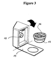
- the cleaning installation comprises, as an example of embodiment, a frame 1 in the form of a column defining a enclosure 2 inside which can be installed a barrel 3 for cleaning fluid storage.
- This frame 1 also incorporates all the elements necessary for operation of the installation. These elements will described below.
- This frame 1 is closed in its upper part by a tank constituting the enclosure 4 for cleaning the installation.
- This enclosure 4 is itself closed by means of a member cover type shutter 5 consisting of one or more elements.
- the shutter member 5 consists of two elements of closure pivoting around the side edges of the tank. These closing elements, in the closed position of the enclosure 4, are joined together and cooperate with a stationary support 6 provided with a through hole allowing the connection of an exhaust pipe 7 harmful solvent vapors with the interior of the enclosure 4 of cleaning.
- This cleaning enclosure 4 has, in its bottom side forming an opening allowing the emptying of its content in the fluid storage barrel 3 connected to said enclosure by appropriate connecting means.
- the frame 1 has, on its front face, a door 8 allowing the introduction of the barrel 3 of cleaning fluid to the interior of the enclosure 2 delimited by the frame 1 of the installation.
- Rolling elements 9 can be provided in the bottom face of said frame 1 for facilitate the introduction and handling of the keg 3 during of its introduction or extraction from said frame 1.
- said frame also includes a housing 10 inside which is arranged a read / write device 15 a data carrier 16 which will be described below.
- This case 10 is in this case equipped with a folding flap 19 allowing access to said read / write device 15 from the outside of the frame 1.
- the cavity thus delimited by said housing 10 is also used for receiving a support data 16 coupled to one of the elements of the keg 3 of cleaning fluid storage.
- this housing 10 is omitted.
- the read / write device 15, arranged in the housing 10, is connected by appropriate wiring to a control and command (not shown) of said installation.
- This control and command unit arranged inside the enclosure 2, includes for example a microcontroller integrating programming logic IT and associated electronic intelligence. This logic allows, in addition, a very great flexibility of operation and total flexibility in the definition cleaning parameters, especially in sequencing or the combination of wash and rinse times like any other option linked to the new conditions to which the machine could evolve (filling of another reserve, drying, etc.) and in the limits set by the control and command unit, in particular by the number of predefined inputs / outputs.
- the control and command unit is itself equipped appropriate wiring to connect it in particular to mechanical, electronic, hydraulic interfaces, tires which will be described below.
- a control keyboard 21 comprising at least one button on / off and possibly a crystal display liquids or LEDs to display for example the number of operating cycles executed by the installation.
- the frame 1 possibly includes, inside its enclosure 2, a second tank constituting a reserve 11 cleaning fluid called rinse reserve.
- the control and command unit is connected at the output to mechanical, electronic, hydraulic or tires and possibly with at least one actuator, these interfaces and possibly the actuator (s) ensuring the supply of cleaning fluid to one or several circuits used during a cycle of operation of the installation, each cycle of operation generally comprising at least one washing operation and rinsing operation.
- the actuator can be deleted in the case of a system supply of cleaning fluid to enclosure 4 of Venturi cleaning.
- the pumps arranged inside the enclosure 2 delimited by the frame 1, can be of variable number.
- the installation comprises three pumps P1, P2, P3.
- the installation comprises at least one circuit of washing 12 in closed loop established between barrel 3 of cleaning fluid storage and enclosure 4 of cleaning, a second washing circuit 13, called the rinsing, established between a reserve 11 of rinsing fluid and the cleaning enclosure 4, the fluid supply from cleaning of the rinsing reserve 11 being carried out manually or via a circuit called filling 14, this circuit 14 connecting the barrel 3 of storage of cleaning fluid and said reserve 11.
- the pump P1 of the flushing circuit 13 is supplied with air through the solenoid valve EV1 acting as an interface and controlled in operation by the control and command unit.
- the pump P2 of the washing circuit 12 is supplied with air at through the solenoid valve EV2 while the pump P3 of the filling circuit 14 is supplied with air through the solenoid valve EV3.
- the rate wear of these actuators is limited because they are not subject to the influence of corrosive liquids such as solvents.
- the most frequently used pumps are diaphragm pumps. If we place our in a explosive environment, pneumatic diaphragm pumps will be preferred, the actuators then being constituted by solenoid valves allowing or not supplying pressurized air. The compressed air supply takes place at a pressure of the order of 7 bars.
- the diaphragm pumps used are coupled to electric motors and are powered by through the control of static relays which constitute interfaces. An energy exclusively electric is then used eliminating any need a source of compressed air.
- the operation of the installation, and in particular the supply of cleaning fluid to these circuits is controlled from the control and command unit arranged inside the enclosure 2 of the frame 1 of the installation.
- This pilot operating unit of said installation from at least one signal said operating authorization master whose emission is subject to a new placement of the cleaning.
- This master authorization signal of operation is produced by at least one sensor such a sensor for detecting the presence of the barrel of fluid cleaning, a sensor for measuring the level of the cleaning in reserve 11, a sensor for measuring the level of cleaning fluid in barrel 3 of cleaning.
- a pressure capable of detecting the presence of the storage barrel 3 cleaning fluid in enclosure 2 of frame 1 is used.
- This control and command unit also controls stopping said installation from at least one signal said master of operating ban which the issue is subject to the measurement and calculation of the value of a datum characteristic of the defilement of cleaning fluid and at a predetermined value of this same given.
- the values of the characteristic data of the cleaning fluid stains are expressed in a unit or a combination of units such as a level of fluid, number of cycles, operating time. Each value of the data can be measured and / or calculated in real time and continuously by appropriate means of said installation and compared with a predetermined value. In the example described below, the characteristic data of the cleaning fluid contamination will be expressed in number of plant operating cycles still called cleaning cycles.
- This data will be measured at by means of a counter incrementing after each cycle of cleaning in such a way that when it reaches a value predetermined cycles, it stops the installation. he can also be expected, in simpler versions of the installation, whether the data is measured by a sensor such as, for example, a sensor for measuring the level of cleaning fluid in the rinsing reserve 11 which, when it detects a fluid level value of predetermined cleaning in reserve 11, emits a signal which causes the shutdown of said installation. Once this stop signal issued, it is mandatory to a new installation of cleaning fluid.
- This new set up will mean in the most case simple by replacing the barrel 3 for storing the fluid cleaning so as to fill the rinsing reserve 11 with a new cleaning fluid and carry out the washing and rinsing operations with a clean cleaning fluid.
- a system is judged by some to be insufficiently coercive towards the user. Indeed, the user can reuse the even was to carry out new operations of cleaning. In this case, the solvent, recovered after these new washing and rinsing operations, will particularly soiled.
- the support data 16, integrated or mechanically coupled to one of the constituent elements (plug 17 or body) of the barrel 3 of cleaning fluid storage and possibly mounted removably on the latter, is a label electronic or a passive smart card with memory scalable.
- Data exchanges between the read / write 15 and the data medium placed or not in contact allow the transmission of a stream two-way information.
- this data carrier 16 is an integrated chip in the cap 17 of the barrel 3 for storing the fluid cleaning. After opening of the fluid storage barrel 3 cleaning, this plug 17 is placed in contact with the read / write device 15 for reading data from said data carrier 16.
- Lines 1, 2 and 7 are data written on the chip by the manufacturer and lines 3, 4, 5, 6, 8 and 9 are data written on the chip by the machine.
- Line 7 is reprogrammable data.
- Line 3 is a given resident in the machine for identification.
- Line 9 consists of coded data to control and report either actions not in accordance with use normal machine, such as organ opening shutter 5 during an operating cycle, removal of the storage drum 3 during a cycle either to report faults.
- the manufacturer of solvent must have a computer reading system and writing electronic chips to charge the data from preset files and to collect information stored for analysis. These information should allow the solvent manufacturer to carry out a rapid and reliable reprocessing of said solvent, this has a lower cost.
- the data extracted from a data carrier 16 by the read / write 15 integrated in the control and command, is coupled with data identifying the data carrier 16, that is to say of the smart card, to prevent the substitution of a data medium 16 by another data medium as long as the number of predetermined wash cycles is not reached. From this done, when the user has set up a keg 3 of cleaning liquid storage in the installation, if subsequently decides to replace this keg 3 with another keg, he can only do this from the moment the credit of the data carrier 16 will have been completely exhausted. As this was clarified above in the content of the chip there sensors may be provided to specify to the manufacturer of resolve incidents encountered during a certain number of operating cycles.
- the sensor signals such as a keg presence sensor cleaning fluid storage, presence sensor of the data carrier, an organ opening sensor shutter 5 during an operating cycle, connected to the control and command unit are received by said unit then transmitted and stored in said storage medium data 16 through the read / write 15 so as to identify any incident during the period of use corresponding to the predetermined number of operating cycles. So the solvent manufacturer may notice if the user has attempted, for a number of operating cycles predetermined, to replace the data medium 16 with a other data carrier.
- the sensor signals such as a keg presence sensor cleaning fluid storage, presence sensor of the data carrier, an organ opening sensor shutter 5 during an operating cycle
- the read / write 15 of the installation is arranged to the interior of the enclosure 2 delimited by the frame 1 of so as to prevent, during the operation of installation, any loss or damage to the barrel 3 when the chip 16 is integrated in the plug 17 of the barrel 3 for storing the cleaning fluid.
- the control and command controls the washing times, rinsing and possibly the volume of the reserve 11 of which are preprogrammed in the said control and command and / or provided by the support of data 16.
- this data is contained in the data carrier, it is possible, for each keg 3 of cleaning fluid storage, to adapt the times of washing and rinsing. It is also possible to adapt wash and rinse times for each cycle operating in such a way as to ensure maximum efficiency washing.
- the rinsing time increases in line with the number of operating cycles executed from emission of the master operating authorization signal of the machine. In this way, because the cleaning fluid is particularly soiled after a certain number of operating cycles, the same efficiency is maintained washing by increasing the rinsing time with a fluid clean.
- the cleaning chamber is in turn equipped with nozzles 18 for cleaning and / or rinses arranged at the outlet of the cleaning circuits and / or rinsing.
- nozzles 18 may include a part sprinkling and a circulation part.
- Some nozzles (at minus one) are pivotally mounted on a support in order to be able to occupy a first position substantially vertical in the absence of objects 20 to be cleaned inside said cleaning enclosure 4 and a tilted position when objects to be cleaned, such as paint guns 20 are introduced on said nozzle by their cannon.
- This inclined position of the nozzles is obtained through a pistons support inclined plane.
- the nozzles are recalled in their vertical position by elastic return means.
- the nozzles are arranged in a manner known per se inside of the cleaning chamber so that they guarantee a supply of cleaning fluid to the circulation point to ensure cleaning of inside the gun and at the spray point for allow spraying of cleaning fluid accessories, such as bowls, lid, outside of the pistol and strainer.
- a barrel 3 for storing cleaning fluid is placed at the interior of enclosure 2 of frame 1.
- This action is detected by a C1 drum presence sensor.
- This sensor C1 generates the transmission of a master authorization signal from operation of the installation.
- This signal triggers in particular the filling of the rinsing reserve 11 with actuation of the pump P3 linked to the opening of the solenoid valve EV3 during the preliminary phase, called initialization, cleaning cycles and whose confirmation is subject to reaching a level sufficient in the reserve.
- This action is detected by a reserve level sensor C2.
- This sensor generates the emission of a second signal.
- the cap 17 of the barrel 3 incorporating a chip 16 is placed in contact with the read / write device 15 of the installation.
- This positioning of the chip 16 causes the emission, by a C3 chip positioning sensor, third signal said slave towards the control unit and command which then begins reading and writing the data carrier 16.
- the operation of the installation can be controlled, inside the time range between the transmission of said signals operating authorization and prohibition masters operation, by command or stop signals said slaves, said signals being produced by sensors, such as a C4 opening detection sensor of the shutter member of the cleaning enclosure.
- slave control signal means a signal whose the emission will only have an effect on the installation from when it will be issued in the meantime [master signal operating authorization - master signal operating ban].
- the P2 pump is operated during a washing time predetermined then the pump P1 is activated for one predetermined rinse time. All cleaning fluid introduced into the cleaning chamber 4 is recovered in was 3. It should be noted that a solenoid valve additional, connected to the nozzle circuit, could be used for drying said objects by feeding said nozzles of the cleaning chamber 4 only in pressurized air.
- a data corresponding to the new value of cycles of executable operation (eg N-1) is written in data carrier 16 by the storage device read / write 15.
Landscapes
- Cleaning By Liquid Or Steam (AREA)
Claims (15)
- Einrichtung zum Reinigen verschiedener Gegenstände, etwa von Farbspritzpistolen, mittels einer Reinigungsflüssigkeit, etwa eines Lösungsmittels, die einer Aufbereitung zu unterziehen ist, umfassend wenigstens ein Reinigungsbehältnis (4), das mittels eines Verschlußorgans verschlossen ist und in dessen Innern die zu reinigenden Gegenstände angeordnet werden, wenigstens ein Reinigungsflüssigkeitsgebinde (3), das als Aufbewahrungsbehälter für die Reinigungsflüssigkeit dient, wobei dieses Gebinde (3) abtrennbar mit dem besagten Reinigungsbehältnis (4) und gegebenenfalls mit einer als Spülreserve bezeichneten Reinigungsflüssigkeitsreserve (11) verbunden ist, um wenigstens die Zuleitung von Reinigungsflüssigkeit zu dem besagten Reinigungsbehältnis (4) und gegebenenfalls zur Spülreserve (11) und/oder die Rückleitung der gebrauchten Reinigungsflüssigkeit aus dem Reinigungsbehältnis (4) herbeizuführen, dadurch gekennzeichnet, daß die Einrichtung mit einer Kontroll- und Steuereinheit (16) ausgerüstet ist, die den Betrieb der besagten Einrichtung ausgehend von wenigstens einem als Mastersignal für die Betriebsfreigabe bezeichneten Signal steuert, dessen Ausgabe durch eine Neueinbringung von Reinigungsflüssigkeit (3) geregelt wird, und die das Abschalten der besagten Einrichtung ausgehend von wenigstens einem als Mastersignal für die Betriebssperre bezeichneten Signal steuert, dessen Ausgabe durch die Messung und/oder an die Berechnung des Werts eines Kenndatums für die Verschmutzung der Reinigungsflüssigkeit und durch einen vorbestimmten Wert ebendieses Kenndatums geregelt wird.
- Reinigungseinrichtung nach Anspruch 1,
dadurch gekennzeichnet, daß das Mastersignal für die Betriebsfreigabe durch wenigstens einen Sensor, etwa einen Geber zur Erfassung des Vorhandenseins des Reinigungsflüssigkeitsgebindes (3), einen Meßfühler zur Messung des Reinigungsflüssigkeitsstands in der Reserve, einen Meßfühler zur Messung des Reinigungsflüssigkeitsstands im Reinigungsflüssigkeitsgebinde, erzeugt wird. - Reinigungseinrichtung nach Anspruch 1,
dadurch gekennzeichnet, daß die Werte des Kenndatums für die Verschmutzung der Reinigungsflüssigkeit in einer Einheit oder in einer Kombination von Einheiten, etwa Flüssigkeitsstand, Durchlaufzahl, Betriebszeit, ausgedrückt werden, wobei jeder Wert des Kenndatums in Echtzeit und durchgehend durch geeignete Mittel der besagten Einrichtung gemessen und/oder berechnet und mit einem vorbestimmten Wert verglichen werden kann. - Reinigungseinrichtung nach einem der Ansprüche 1 bis 3,
dadurch gekennzeichnet, daß die Kontroll- und Steuereinheit ausgangsseitig mit mechanischen, elektronischen, hydraulischen oder pneumatischen Schnittstellen und gegebenenfalls mit wenigstens einem Stellglied verbunden ist, wobei diese Schnittstellen und gegebenenfalls das bzw. die Stellglieder die Zuleitung von Reinigungsflüssigkeit zu einem oder mehreren Kreisläufen (12, 13) bewirken, die während eines Betriebsdurchlaufs der Einrichtung verwendet werden, wobei jeder Betriebsdurchlauf im allgemeinen wenigstens einen Waschvorgang und wenigstens einen Spülvorgang umfaßt. - Reinigungseinrichtung nach Anspruch 4,
dadurch gekennzeichnet, daß die Einrichtung wenigstens einen geschlossenen Waschkreislauf (12) umfaßt, der zwischen dem Gebinde (3) zur Aufbewahrung der Reinigungsflüssigkeit und dem Reinigungsbehältnis (4) hergestellt ist, während ein als Spülkreislauf bezeichneter zweiter Waschkreislauf (13) zwischen einer Reserve (11) mit Reinigungsflüssigkeit und dem Reinigungsbehältnis (4) hergestellt ist, wobei die Zuleitung von Reinigungsflüssigkeit zur Spülreserve (11) manuell oder über einen als Füllkreislauf bezeichneten Kreislauf (14) erfolgt, wobei dieser Kreislauf das Reinigungsflüssigkeitsgebinde (3) mit der besagten Reserve (11) verbindet. - Reinigungseinrichtung nach einem der Ansprüche 4 oder 5,
dadurch gekennzeichnet, daß die Kreisläufe (13, 12, 14), die auf einem Teil ihrer Länge gemeinsam ausgeführt sein können, jeweils aus einer an dem besagten Kreislauf installierten Pumpe (P1, P2, P3) bestehen, wobei diese Pumpe (P1, P2, P3) mit einer Druckluftquelle mittels eines Luftzuleitungskreislaufs mit kontrolliertem Luftdurchsatz mittels eines Magnetventils (EV1, EV2, EV3) verbunden ist, dessen Öffnen/Schließen durch ein Signal der Kontroll- und Steuereinheit gesteuert wird. - Reinigungseinrichtung nach einem der Ansprüche 1 bis 6,
dadurch gekennzeichnet, daß der Betrieb der Einrichtung innerhalb der Zeitspanne zwischen der Ausgabe der besagten Mastersignale für die Betriebsfreigabe und für die Betriebssperre durch als Slavesignale bezeichnete Ein- oder Abschaltsignale gesteuert wird, wobei die besagten Signale durch Sensoren, etwa einen Sensor zur Erfassung der Öffnung des Verschlußorgans (5) des Reinigungsbehältnisses (4), erzeugt werden. - Reinigungseinrichtung nach einem der Ansprüche 1 bis 6,
dadurch gekennzeichnet, daß der Betrieb der Einrichtung innerhalb der Zeitspanne zwischen der Ausgabe der besagten Mastersignale für die Betriebsfreigabe und die Betriebssperre durch den Empfang wenigstens eines Datums geregelt wird, das durch eine Lese-/Schreibvorrichtung (15) aus einem Datenträger (16), etwa aus einem elektronisch lesbaren Etikett oder aus einer Chipkarte, ausgelesen wird, der an das Gebinde zur Aufbewahrung der Reinigungsflüssigkeit gekoppelt ist, wobei dieses Kenndatum für die Verschmutzung der Reinigungsflüssigkeit nach jeder Auslösung eines Betriebsdurchlaufs der Einrichtung aktualisiert wird, um nach einer vorbestimmten Anzahl von Betriebsdurchläufen die Wiedereinschaltung der Einrichtung zu verhindern, wobei diese Wiedereinschaltung erst nach einer Neueinbringung von Reinigungsflüssigkeit und nach der Ersetzung des Datenträgers (16) mit erschöpftem Guthaben durch einen neuen Datenträger erfolgen kann. - Reinigungseinrichtung nach Anspruch 8,
dadurch gekennzeichnet, daß das besagte Datum, das durch eine in die Kontroll- und Steuereinheit integrierte Lese-/Schreibvorrichtung (15) aus einem Datenträger (16) ausgelesen wird, an ein Kenndatum des Datenträgers gekoppelt ist, um den Austausch eines Datenträgers durch einen anderen Datenträger zu verhindern, solange die vorbestimmte Anzahl der Waschdurchläufe nicht erreicht ist. - Reinigungseinrichtung nach Anspruch 8,
dadurch gekennzeichnet, daß die Signale von Sensoren, etwa von einem Geber für das Vorhandensein des Gebindes zur Aufbewahrung der Reinigungsflüssigkeit, einem Geber für das Vorhandensein des Datenträgers, einem Geber für die Öffnung des Verschlußorgans während eines Betriebsdurchlaufs, durch die besagte Einheit empfangen, anschließend übertragen und in dem besagten Datenträger (16) über die Lese-/Schreibvorrichtung (15) gespeichert werden, um jeden Zwischenfall während der Benutzungsdauer entsprechend der vorbestimmten Anzahl von Betriebsdurchläufen zu erfassen. - Reinigungseinrichtung nach einem der Ansprüche 8 bis 10,
dadurch gekennzeichnet, daß der integrierte oder mechanisch an einen der Bestandteile (Verschlußstopfen (17) oder Körper) des Gebindes (3) zur Aufbewahrung der Reinigungsflüssigkeit gekoppelte und gegebenenfalls abnehmbar an letzterem angebrachte Datenträger (16) ein elektronisch lesbares Etikett oder eine passive Chipkarte mit erweiterbarem Speicher ist, wobei der Datenaustausch zwischen der Lese-/Schreibvorrichtung und dem Datenträger, die in ständigem Kontakt angeordnet sind oder nicht, die Übertragung eines bidirektionalen Datenflusses ermöglicht. - Reinigungseinrichtung nach einem der Ansprüche 8 bis 11,
dadurch gekennzeichnet, daß der Datenträger (16) durch die Einrichtung geschriebene Daten und/oder umprogrammierbare Daten und/oder durch den Hersteller der Reinigungsflüssigkeit geschriebene residente Daten enthält. - Reinigungseinrichtung nach einem der Ansprüche 1 bis 12,
dadurch gekennzeichnet, daß die Kontroll- und Steuereinheit die Wasch- und Spülzeiten sowie gegebenenfalls das Volumen der Spülreserve (11) steuert, die in der besagten Einheit vorprogrammiert sind und/oder durch den Datenträger (16) geliefert werden. - Reinigungseinrichtung nach einem der Ansprüche 1 bis 13,
dadurch gekennzeichnet, daß sich jeder Betriebsdurchlauf aus einer Waschzeit und einer Spülzeit zusammensetzt, wobei die Spülzeit in Übereinstimmung mit der Anzahl der ausgeführten Betriebsdurchläufe ab der Ausgabe des Mastersignals für die Betriebsfreigabe der Maschine zunimmt. - Reinigungseinrichtung nach einem der Ansprüche 1 bis 15,
dadurch gekennzeichnet, daß das Reinigungsbehältnis (4) mit Reinigungs- und/oder Spüldüsen (18) ausgerüstet ist, die am Ausgang der Reinigungs- (12) und/oder Spülkreisläufe (13) angeordnet sind, wobei wenigstens eine Düse (18) schwenkbar auf einem Träger gelagert ist, so daß sie eine in etwa vertikale erste Position bei Nichtvorhandensein von zu reinigenden Gegenständen im Innern des besagten Reinigungsbehältnisses (4) und eine geneigte Position einnehmen kann, wenn die zu reinigenden Gegenstände, etwa Farbspritzpistolen (20), durch ihr Rohr an der besagten Düse eingesetzt sind.
Applications Claiming Priority (2)
| Application Number | Priority Date | Filing Date | Title |
|---|---|---|---|
| FR9604059A FR2746679B1 (fr) | 1996-04-01 | 1996-04-01 | Installation de nettoyage d'objets divers |
| FR9604059 | 1996-04-01 |
Publications (2)
| Publication Number | Publication Date |
|---|---|
| EP0799651A1 EP0799651A1 (de) | 1997-10-08 |
| EP0799651B1 true EP0799651B1 (de) | 2001-01-10 |
Family
ID=9490776
Family Applications (1)
| Application Number | Title | Priority Date | Filing Date |
|---|---|---|---|
| EP19970400721 Expired - Lifetime EP0799651B1 (de) | 1996-04-01 | 1997-03-28 | Einrichtung zum Reinigen verschiedener Gegenstände |
Country Status (3)
| Country | Link |
|---|---|
| EP (1) | EP0799651B1 (de) |
| DE (1) | DE69703858T2 (de) |
| FR (1) | FR2746679B1 (de) |
Families Citing this family (2)
| Publication number | Priority date | Publication date | Assignee | Title |
|---|---|---|---|---|
| GB0405337D0 (en) * | 2004-03-09 | 2004-04-21 | Petty Robert H | Paint spraygun cleaner |
| US9265400B2 (en) * | 2005-04-22 | 2016-02-23 | Duke Manufacturing Co. | Commercial kitchenware washers and related methods |
Family Cites Families (3)
| Publication number | Priority date | Publication date | Assignee | Title |
|---|---|---|---|---|
| SE7902896L (sv) * | 1979-04-02 | 1980-10-03 | Axenta Ind Ab | Fororeningsindikator vid tvettmaskin |
| GB2195737B (en) * | 1986-09-09 | 1991-01-30 | Leif Einar Stern | Container for hazardous detergents |
| SE500681C2 (sv) * | 1990-02-19 | 1994-08-08 | Drester Ab | Anordning för rengöring av sprutpistoler |
-
1996
- 1996-04-01 FR FR9604059A patent/FR2746679B1/fr not_active Expired - Fee Related
-
1997
- 1997-03-28 DE DE1997603858 patent/DE69703858T2/de not_active Expired - Fee Related
- 1997-03-28 EP EP19970400721 patent/EP0799651B1/de not_active Expired - Lifetime
Also Published As
| Publication number | Publication date |
|---|---|
| FR2746679B1 (fr) | 1998-05-15 |
| DE69703858T2 (de) | 2001-08-16 |
| DE69703858D1 (de) | 2001-02-15 |
| FR2746679A1 (fr) | 1997-10-03 |
| EP0799651A1 (de) | 1997-10-08 |
Similar Documents
| Publication | Publication Date | Title |
|---|---|---|
| EP1417391B1 (de) | Hochdruck-beschmiervorrichtung | |
| EP0799651B1 (de) | Einrichtung zum Reinigen verschiedener Gegenstände | |
| FR2793927A1 (fr) | Procede et dispositif de distribution de bouteilles de gaz | |
| EP2328831B1 (de) | Übergabeförderer mit automatischem behälterwaschsystem | |
| EP0041457A2 (de) | Ausgabeautomat, mit herausnehmbarer Geldkassette und Verwaltungseinrichtung für diese Kassetten | |
| WO2005016549A2 (fr) | Dispositif de diffusion d'un liquide dans l'atmosphere incorporant des moyens vibratoires de debouchage d'une buse de pulverisation | |
| FR2890944A1 (fr) | Appareil electromenager comportant des moyens pour detecter l'ouverture d'un bouchon. | |
| FR3004168A3 (fr) | Distributeur automatique de granules de bois | |
| EP1172305A1 (de) | Aufbewahrungs- und Ausgabevorrichtung für ein Produkt, insbesondere einen Duftstoffträger | |
| FR2785817A1 (fr) | Robinet et extincteur portable a pression permanente equipe d'un tel robinet | |
| EP3401239A1 (de) | Sammelsystem von bioabfällen | |
| FR2873600A1 (fr) | Installation de lavage de conteneurs. | |
| WO2003068411A1 (fr) | Dispositif de diffusion d'un liquide dans l'atmosphere incorporant des moyens de debouchage d'une buse de pulverisation | |
| FR2846254A1 (fr) | Dispositif de filtration integrant le controle du volume echantillonne | |
| FR2917804A1 (fr) | Systeme de raccordement securise d'une bouteille de gaz a une vanne d'un circuit d'utilisation | |
| FR2911783A1 (fr) | Dispositif sanitaire de pulverisation de liquides securise | |
| FR2896229A1 (fr) | Systeme de conditionnement en fluide de reservoirs reutilisables | |
| FR2712321A1 (fr) | Urinoir d'un nouveau type. | |
| FR2867592A1 (fr) | Appareil de distribution de produit consommable et support pour cet appareil | |
| FR2807631A1 (fr) | Dispositif pour contenir et distribuer des produits cosmetiques liquides | |
| DE50310973D1 (de) | Spender zum dosierten Abgeben eines in einem Behälter befindlichen flüssigen Mediums | |
| FR2838321A1 (fr) | Dispositif sanitaire de pulverisation securise | |
| FR2734794A1 (fr) | Dispositif pour le rangement de petits objets et pour la gestion et la surveillance des entrees et sorties de ces petits objets | |
| EP4544908A1 (de) | Verschlussvorrichtung und vorrichtung zum entfernen von pflanzenschutzmitteln | |
| FR2832171A1 (fr) | Dispositif de reception d'objets |
Legal Events
| Date | Code | Title | Description |
|---|---|---|---|
| PUAI | Public reference made under article 153(3) epc to a published international application that has entered the european phase |
Free format text: ORIGINAL CODE: 0009012 |
|
| AK | Designated contracting states |
Kind code of ref document: A1 Designated state(s): DE FR GB |
|
| 17P | Request for examination filed |
Effective date: 19971021 |
|
| GRAG | Despatch of communication of intention to grant |
Free format text: ORIGINAL CODE: EPIDOS AGRA |
|
| 17Q | First examination report despatched |
Effective date: 20000414 |
|
| GRAG | Despatch of communication of intention to grant |
Free format text: ORIGINAL CODE: EPIDOS AGRA |
|
| GRAH | Despatch of communication of intention to grant a patent |
Free format text: ORIGINAL CODE: EPIDOS IGRA |
|
| GRAH | Despatch of communication of intention to grant a patent |
Free format text: ORIGINAL CODE: EPIDOS IGRA |
|
| GRAA | (expected) grant |
Free format text: ORIGINAL CODE: 0009210 |
|
| AK | Designated contracting states |
Kind code of ref document: B1 Designated state(s): DE FR GB |
|
| REF | Corresponds to: |
Ref document number: 69703858 Country of ref document: DE Date of ref document: 20010215 |
|
| GBT | Gb: translation of ep patent filed (gb section 77(6)(a)/1977) |
Effective date: 20010417 |
|
| PLBE | No opposition filed within time limit |
Free format text: ORIGINAL CODE: 0009261 |
|
| STAA | Information on the status of an ep patent application or granted ep patent |
Free format text: STATUS: NO OPPOSITION FILED WITHIN TIME LIMIT |
|
| REG | Reference to a national code |
Ref country code: GB Ref legal event code: IF02 |
|
| 26N | No opposition filed | ||
| PGFP | Annual fee paid to national office [announced via postgrant information from national office to epo] |
Ref country code: GB Payment date: 20070118 Year of fee payment: 11 |
|
| PGFP | Annual fee paid to national office [announced via postgrant information from national office to epo] |
Ref country code: DE Payment date: 20070322 Year of fee payment: 11 |
|
| GBPC | Gb: european patent ceased through non-payment of renewal fee |
Effective date: 20080328 |
|
| PG25 | Lapsed in a contracting state [announced via postgrant information from national office to epo] |
Ref country code: DE Free format text: LAPSE BECAUSE OF NON-PAYMENT OF DUE FEES Effective date: 20081001 |
|
| PG25 | Lapsed in a contracting state [announced via postgrant information from national office to epo] |
Ref country code: GB Free format text: LAPSE BECAUSE OF NON-PAYMENT OF DUE FEES Effective date: 20080328 |
|
| PGFP | Annual fee paid to national office [announced via postgrant information from national office to epo] |
Ref country code: FR Payment date: 20090130 Year of fee payment: 13 |
|
| REG | Reference to a national code |
Ref country code: FR Ref legal event code: ST Effective date: 20101130 |
|
| PG25 | Lapsed in a contracting state [announced via postgrant information from national office to epo] |
Ref country code: FR Free format text: LAPSE BECAUSE OF NON-PAYMENT OF DUE FEES Effective date: 20100331 |