EP0799622B1 - Automatische Vorrichtung zur Sanierung von Sanitärräumen - Google Patents
Automatische Vorrichtung zur Sanierung von Sanitärräumen Download PDFInfo
- Publication number
- EP0799622B1 EP0799622B1 EP97400678A EP97400678A EP0799622B1 EP 0799622 B1 EP0799622 B1 EP 0799622B1 EP 97400678 A EP97400678 A EP 97400678A EP 97400678 A EP97400678 A EP 97400678A EP 0799622 B1 EP0799622 B1 EP 0799622B1
- Authority
- EP
- European Patent Office
- Prior art keywords
- module
- spraying
- plant according
- supply module
- tank
- Prior art date
- Legal status (The legal status is an assumption and is not a legal conclusion. Google has not performed a legal analysis and makes no representation as to the accuracy of the status listed.)
- Expired - Lifetime
Links
- 238000011012 sanitization Methods 0.000 title claims description 15
- 238000005507 spraying Methods 0.000 claims description 27
- 239000007788 liquid Substances 0.000 claims description 8
- 230000001105 regulatory effect Effects 0.000 claims description 2
- 230000001960 triggered effect Effects 0.000 claims description 2
- 238000009434 installation Methods 0.000 description 21
- 239000007921 spray Substances 0.000 description 20
- 239000000047 product Substances 0.000 description 17
- 238000010926 purge Methods 0.000 description 9
- 230000006870 function Effects 0.000 description 2
- 239000012263 liquid product Substances 0.000 description 2
- 206010014357 Electric shock Diseases 0.000 description 1
- 101150096607 Fosl2 gene Proteins 0.000 description 1
- 239000004698 Polyethylene Substances 0.000 description 1
- 230000015556 catabolic process Effects 0.000 description 1
- 230000006835 compression Effects 0.000 description 1
- 238000007906 compression Methods 0.000 description 1
- 239000000470 constituent Substances 0.000 description 1
- 230000007423 decrease Effects 0.000 description 1
- 238000010586 diagram Methods 0.000 description 1
- 230000005611 electricity Effects 0.000 description 1
- 238000012423 maintenance Methods 0.000 description 1
- -1 polyethylene Polymers 0.000 description 1
- 229920000573 polyethylene Polymers 0.000 description 1
- 239000012815 thermoplastic material Substances 0.000 description 1
- XLYOFNOQVPJJNP-UHFFFAOYSA-N water Substances O XLYOFNOQVPJJNP-UHFFFAOYSA-N 0.000 description 1
Images


Classifications
-
- A—HUMAN NECESSITIES
- A61—MEDICAL OR VETERINARY SCIENCE; HYGIENE
- A61L—METHODS OR APPARATUS FOR STERILISING MATERIALS OR OBJECTS IN GENERAL; DISINFECTION, STERILISATION OR DEODORISATION OF AIR; CHEMICAL ASPECTS OF BANDAGES, DRESSINGS, ABSORBENT PADS OR SURGICAL ARTICLES; MATERIALS FOR BANDAGES, DRESSINGS, ABSORBENT PADS OR SURGICAL ARTICLES
- A61L9/00—Disinfection, sterilisation or deodorisation of air
- A61L9/14—Disinfection, sterilisation or deodorisation of air using sprayed or atomised substances including air-liquid contact processes
-
- A—HUMAN NECESSITIES
- A61—MEDICAL OR VETERINARY SCIENCE; HYGIENE
- A61L—METHODS OR APPARATUS FOR STERILISING MATERIALS OR OBJECTS IN GENERAL; DISINFECTION, STERILISATION OR DEODORISATION OF AIR; CHEMICAL ASPECTS OF BANDAGES, DRESSINGS, ABSORBENT PADS OR SURGICAL ARTICLES; MATERIALS FOR BANDAGES, DRESSINGS, ABSORBENT PADS OR SURGICAL ARTICLES
- A61L2/00—Methods or apparatus for disinfecting or sterilising materials or objects other than foodstuffs or contact lenses; Accessories therefor
- A61L2/16—Methods or apparatus for disinfecting or sterilising materials or objects other than foodstuffs or contact lenses; Accessories therefor using chemical substances
- A61L2/22—Phase substances, e.g. smokes, aerosols or sprayed or atomised substances
-
- A—HUMAN NECESSITIES
- A61—MEDICAL OR VETERINARY SCIENCE; HYGIENE
- A61L—METHODS OR APPARATUS FOR STERILISING MATERIALS OR OBJECTS IN GENERAL; DISINFECTION, STERILISATION OR DEODORISATION OF AIR; CHEMICAL ASPECTS OF BANDAGES, DRESSINGS, ABSORBENT PADS OR SURGICAL ARTICLES; MATERIALS FOR BANDAGES, DRESSINGS, ABSORBENT PADS OR SURGICAL ARTICLES
- A61L2/00—Methods or apparatus for disinfecting or sterilising materials or objects other than foodstuffs or contact lenses; Accessories therefor
- A61L2/24—Apparatus using programmed or automatic operation
-
- B—PERFORMING OPERATIONS; TRANSPORTING
- B05—SPRAYING OR ATOMISING IN GENERAL; APPLYING FLUENT MATERIALS TO SURFACES, IN GENERAL
- B05B—SPRAYING APPARATUS; ATOMISING APPARATUS; NOZZLES
- B05B12/00—Arrangements for controlling delivery; Arrangements for controlling the spray area
- B05B12/02—Arrangements for controlling delivery; Arrangements for controlling the spray area for controlling time, or sequence, of delivery
-
- B—PERFORMING OPERATIONS; TRANSPORTING
- B05—SPRAYING OR ATOMISING IN GENERAL; APPLYING FLUENT MATERIALS TO SURFACES, IN GENERAL
- B05B—SPRAYING APPARATUS; ATOMISING APPARATUS; NOZZLES
- B05B12/00—Arrangements for controlling delivery; Arrangements for controlling the spray area
- B05B12/08—Arrangements for controlling delivery; Arrangements for controlling the spray area responsive to condition of liquid or other fluent material to be discharged, of ambient medium or of target ; responsive to condition of spray devices or of supply means, e.g. pipes, pumps or their drive means
- B05B12/081—Arrangements for controlling delivery; Arrangements for controlling the spray area responsive to condition of liquid or other fluent material to be discharged, of ambient medium or of target ; responsive to condition of spray devices or of supply means, e.g. pipes, pumps or their drive means responsive to the weight of a reservoir or container for liquid or other fluent material; responsive to level or volume of liquid or other fluent material in a reservoir or container
-
- B—PERFORMING OPERATIONS; TRANSPORTING
- B05—SPRAYING OR ATOMISING IN GENERAL; APPLYING FLUENT MATERIALS TO SURFACES, IN GENERAL
- B05B—SPRAYING APPARATUS; ATOMISING APPARATUS; NOZZLES
- B05B9/00—Spraying apparatus for discharge of liquids or other fluent material, without essentially mixing with gas or vapour
- B05B9/03—Spraying apparatus for discharge of liquids or other fluent material, without essentially mixing with gas or vapour characterised by means for supplying liquid or other fluent material
- B05B9/04—Spraying apparatus for discharge of liquids or other fluent material, without essentially mixing with gas or vapour characterised by means for supplying liquid or other fluent material with pressurised or compressible container; with pump
- B05B9/0403—Spraying apparatus for discharge of liquids or other fluent material, without essentially mixing with gas or vapour characterised by means for supplying liquid or other fluent material with pressurised or compressible container; with pump with pumps for liquids or other fluent material
- B05B9/0423—Spraying apparatus for discharge of liquids or other fluent material, without essentially mixing with gas or vapour characterised by means for supplying liquid or other fluent material with pressurised or compressible container; with pump with pumps for liquids or other fluent material for supplying liquid or other fluent material to several spraying apparatus
Definitions
- the present invention relates to automatic installation for the sanitation of one or more enclosures arranged in one or more rooms, provided sanitary facilities, especially for communities.
- EP 485.682 discloses an automatic installation component of a central unit including a control panel order, a tank of liquid product sanitation system provided with a compression device and means for spraying a sanitizing product liquid.
- the tank is connected to the means of spraying through a single tube.
- the product sanitizer contained in the tank and in said tubing is put under low overpressure to be projected into the enclosure as soon as the means of spray.
- the pressurization of the product contained in the tank eliminates any possibility the latter's removability and makes it difficult to refeeding.
- Pressure diversion means are then necessary at the level of the tank to allow the fill through a specific pipe or to intervene on the installation for its maintenance or a particular repair. This known installation is subject to improvement.
- the present invention provides a simplified installation for easy access to different elements, to have a removable tank and to increase the spraying efficiency of the product.
- the installation includes means for actuating the power supply module and the spray module, suitable for allowing separate and autonomous operation of the latter.
- the pressurizing means include a pump low inertia.
- the power module includes a filter mounted at upside down so as to create an air bubble in it.
- the tank is removable.
- the installation comprises purging means constituted a solenoid valve and an additional conduit arranged between the pipeline and the tank.
- the power module has a timer likely to automatically stop putting pressure, after a preset time, in case of rupture a pipe, or if the tank is empty.
- the spray module includes a card electronic to manage its operation, said card comprising memory elements erasable, data such as the presence of a user in said room, triggering and the interruption of spraying, the duration of spraying, the amount of liquid sprayed.
- the operation of the spray module is triggered by actuation a mechanical member such as a lock.
- the liquid is put under a pressure of between 3 and 10 bars, and preferably around 4.5 bars.
- the sanitizing product 4 is put under pressure from around 3 to 10 bars, and preferably around 4.5 bars.
- the pump 10 is of the low inertia type and is therefore likely to respond within approximately 1 / 50th of a second. For example, a pump low inertia electromagnetic is likely to suit.
- the pressure is regulated by a pressure switch 11.
- a filter 12 is mounted upside down, at the outlet of the pump 10. An air bubble 13 is thus created in its upper part and allows to amortize any sudden pressure surges. Filter 12 plays the role a hydropneumatic accumulator. As soon as spraying is carried out, the pump 10 allows compensate, if necessary, for the loss of pressure in the installation. The sanitizing product contained in the tank 9 is never pressurized at any time; only the line 8 is pressurized. So the volume of sanitizer under pressure is low, which limits the risk of fire in the event of a rupture pipeline accidental.
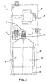
- the reservoir 9 is removable and is shown, for example, with reference to Figure 2, under the shape of a container 14 made of thermoplastic material such as polyethylene.
- An envelope 15 is suitable for receive the container 14.
- a fixing system 16 of the screw type is provided at the upper end of the envelope 15. In this way, the container 14 provided with the casing 15 can be easily screwed on corresponding means of the supply module 2.
- the container 14 has at its upper end (i.e. on the side of the fastening system 16) a diameter greater than the diameter of the container at its lower end.
- the container presents a diameter of 12 cm at its upper end and 11 cm at its lower end. The difference in diameter varies from about 50 mm to 2 cm.
- a sheath 17 is fixed to the supply module 2 and has a longitudinal slot 18 included in the plane tangent to the sheath and parallel to the plane of the module on which all the constituent parts of it are placed.
- the slot 18 has the function of allowing a direct reading of the water level in tank 9, i.e. in container 14 in the example described.
- pump operation is interrupted automatically.
- the alarm light 20 lights up to warn the user of a possible incident or the fact that the tank is empty.
- the pump 10 remains inactive and the indicator 20 remains lit as long as user did not press push button 21 alarm.
- the purge system 22 consists for example of a purge solenoid valve 23 for sucking in air or pipeline 8 and sanitizing product introduce it into a purge conduit 24 opening into the tank 9.
- the function of the purge system 22 is in particular lower the liquid pressure in the installation to atmospheric pressure to allow the user to intervene on it. It is also intended for evacuate excess air when switching on installation.
- the purge system 22 is likely to be primed at by means of the alarm push button 21.
- the power supply device 5 is connected to network 27 (220V - 50 Hz) and is connected either to the system Purge 22 if the alarm push button 21 is engaged, either at pressure switch 11 otherwise.
- the different component parts of the device 3 power supply and safety device 6 are supplied with 220 volts.
- the spray module (s) is (are) supplied with 24 volts.
- the transformer 25 is provided for this purpose to supply the module (s) of spraying with 24 volts alternating or direct current, from the current delivered by the network 27 (220 V).
- the operation indicator light 30 indicates whether the module (s) is (are) supplied.
- the 20 alarm and 30 operation indicators have a different color.
- the light 20 is yellow and 30 is green.
- Accumulator batteries (not shown) are likely to be incorporated into device 5 to provide backup power in the event of a network failure or interruption.
- Each spray module 7 is supplied with product sanitizing via line 8, and electrically supplied at 24 volts by device 5 of the power supply module 2 via cables 31 electrical connections.
- module 7 of spray includes a solenoid valve 32 spraying whose operation is managed by a electronic card 33.
- a nozzle 34 allows the projection of product 4 into the enclosure: it can be integrated into the solenoid valve 32.
- the card 33 makes it possible to trigger the spraying when a condition is met, such as the presence of the user in the enclosure or opening the lock at the user exit. of the timers are likely to be set. So, for example, we can expect a delay of four seconds between opening the lock and spraying for allow the user to leave the enclosure before spray.
- the card 33 is also able to interrupt the spraying after a specified time and preset at using a potentiometer.
- the duration of spraying is depending on the quantity of product required 4 sanitizer to disinfect the enclosure properly and fully.
- the speed of spraying is substantially constant and about 1.5 ml per second for example.
- each spray module 7 different.
- the dimensions and power of module 2 are chosen according to the number and / or of the power of the spray modules, as well as the configuration of the premises and the space allocated to each module.
- the operation of the power supply module 2 and of the spray module (s) 7 is completely separate and autonomous, which reduces the number of connections between modules and simplify their structure.
- the power and spray are likely to be installed easily, without being bothered by structures special premises such as, for example, distant from each other other.
Landscapes
- Health & Medical Sciences (AREA)
- Veterinary Medicine (AREA)
- Life Sciences & Earth Sciences (AREA)
- Animal Behavior & Ethology (AREA)
- General Health & Medical Sciences (AREA)
- Public Health (AREA)
- Epidemiology (AREA)
- Chemical & Material Sciences (AREA)
- Chemical Kinetics & Catalysis (AREA)
- General Chemical & Material Sciences (AREA)
- Nozzles (AREA)
- Disinfection, Sterilisation Or Deodorisation Of Air (AREA)
- Apparatus For Disinfection Or Sterilisation (AREA)
- Toilet Supplies (AREA)
Claims (9)
- Automatische Anlage zur Reinigung von einem oder mehreren abgeschlossenen Bereichen, die an einer oder mehreren Stellen vorgesehen sind, wie Nasszellen, die folgendes aufweist:wobei jedes Zerstäubungsmodul (7) über ein einziges Leitungssystem (8) mit dem Zufuhrmodul (2) verbunden ist,ein Zufuhrmodul, das ein Reservoir (9) für flüssiges Reinigungsprodukt (4) aufweist;mindestens ein Zerstäubungsmodul (7), das einen Zerstäuber (34) aufweist, für das Reinigungsprodukt (4);
wobei die Anlage Mittel zum Unterdrucksetzen des Produktes (4) nur in dem Leitungssystem (8) aufweist, wobei der Druck wesentlich höher ist als der Atmosphärendruck, dadurch gekennzeichnet, dass das Zufuhrmodul eine Bedienungskonsole aufweist, das Zerstäubungsmodul ein Schaltschütz (32) aufweist, und dadurch dass die Anlage Betätigungseinrichtungen für Zufuhrmodul (2) und Zerstäubungsmodul (7) aufweist, die dazu geeignet sind, die getrennte und unabhängige Funktion dieser letzteren zu ermöglichen. - Anlage nach Anspruch 1, dadurch gekennzeichnet dass die Druckaufbau-Einrichtungen eine trägheitsarme Pumpe (10) aufweisen.
- Anlage nach einem der vorhergehenden Ansprüche, dadurch gekennzeichnet, dass das Zufuhrmodul (2) einen Zeitgeber (19) aufweist, der im Falle einen Bruchs eines Leitungssystems oder wenn das Reservoir leer ist, den Druckaufbau nach einer zuvor festgelegten Zeit automatisch anzuhalten vermag.
- Anlage nach einem der vorhergehenden Ansprüche, dadurch gekennzeichnet, dass das Zufuhrmodul (2) ein Filter (12) aufweist, das verkehrt montiert ist, derart, dass in diesem eine Luftblase (13) erzeugt wird.
- Anlage nach einem der vorhergehenden Ansprüche, dadurch gekennzeichnet, dass sie Entleerungseinrichtungen (22) aufweist, die aus einem Schaltschütz (23) und einer zusätzlichen, zwischen Leitungssystem (8) und Reservoir (9) angeordneten Leitung (24) bestehen.
- Anlage nach einem der vorhergehenden Ansprüche, dadurch gekennzeichnet dass das Zerstäubungsmodul eine elektronische Karte (33) aufweist, durch die sich seine Funktionsweise steuern lässt, wobei die Karte löschbare Speicherelemente für Daten, wie Präsenz eines Anwenders vor Ort, Auslösung und Unterbrechung der Zerstäubung, Dauer der Zerstäubung, Menge der zerstäubten Flüssigkeit, aufweist.
- Anlage nach einem der vorhergehenden Ansprüche, dadurch gekennzeichnet, dass die Funktion des Zerstäubungsmoduls (7) durch Betätigung eines mechanischen Organs, wie eines Riegels, ausgelöst wird.
- Anlage nach einem der vorhergehenden Ansprüche, dadurch gekennzeichnet, dass das Reservoir (9) abnehmbar ist.
- Anlage nach einem der vorhergehenden Ansprüche, dadurch gekennzeichnet, dass die Flüssigkeit unter einem Druck von 3 bis 10 bar, vorzugsweise von etwa 4,5 bar steht.
Applications Claiming Priority (2)
| Application Number | Priority Date | Filing Date | Title |
|---|---|---|---|
| FR9604049 | 1996-04-01 | ||
| FR9604049A FR2746651B1 (fr) | 1996-04-01 | 1996-04-01 | Installation automatique pour l'assainissement de locaux tels que sanitaires |
Publications (2)
| Publication Number | Publication Date |
|---|---|
| EP0799622A1 EP0799622A1 (de) | 1997-10-08 |
| EP0799622B1 true EP0799622B1 (de) | 2002-08-07 |
Family
ID=9490769
Family Applications (1)
| Application Number | Title | Priority Date | Filing Date |
|---|---|---|---|
| EP97400678A Expired - Lifetime EP0799622B1 (de) | 1996-04-01 | 1997-03-26 | Automatische Vorrichtung zur Sanierung von Sanitärräumen |
Country Status (5)
| Country | Link |
|---|---|
| US (1) | US5954269A (de) |
| EP (1) | EP0799622B1 (de) |
| JP (1) | JPH105318A (de) |
| DE (1) | DE69714497D1 (de) |
| FR (1) | FR2746651B1 (de) |
Families Citing this family (6)
| Publication number | Priority date | Publication date | Assignee | Title |
|---|---|---|---|---|
| DE212006000068U1 (de) * | 2005-11-11 | 2008-07-31 | Schnitzler Gmbh | Korrosionsschutz-Vorrichtung |
| US20080163817A1 (en) * | 2007-01-04 | 2008-07-10 | Oc Oerlikon Balzers Ag | Apparatus for gas handling in vacuum processes |
| FR2997639B1 (fr) * | 2012-11-08 | 2015-07-31 | Karim Benalikhoudja | Cartouche a obsolescence programmee, de production et de diffusion d'un aerosol, et appareil de diffusion la comportant. |
| US9392915B1 (en) * | 2014-01-24 | 2016-07-19 | Emmanuel Jones | Air freshening toilet seat device |
| CN108126221A (zh) * | 2017-12-25 | 2018-06-08 | 王宝珠 | 一种纳米雾消毒灭菌装置 |
| CN113042242A (zh) * | 2021-03-10 | 2021-06-29 | 机械工业第九设计研究院有限公司 | 一种带有自动补蜡功能的手工喷腊设备 |
Family Cites Families (10)
| Publication number | Priority date | Publication date | Assignee | Title |
|---|---|---|---|---|
| FR2302105A1 (fr) * | 1975-02-27 | 1976-09-24 | Bekoto Sa | Unite de desinfection de volumes clos, notamment de batteries d'incubateurs et d'eclosoirs |
| US4061271A (en) * | 1976-10-13 | 1977-12-06 | Kimbrough Wade L | Control system for high pressure hydraulic system |
| US4324294A (en) * | 1979-02-07 | 1982-04-13 | John McLoughlin | Chemical injection control system for fire fighting |
| US4387850A (en) * | 1980-12-29 | 1983-06-14 | Modern Mill, Inc. | Remote control apparatus for power washers |
| DK162141C (da) * | 1989-04-14 | 1992-03-02 | Accu Air As | Fremgangsmaade til desinfektion af et eller flere lokaler samt anlaeg til udoevelse af fremgangsmaaden |
| EP0485682B1 (de) * | 1990-11-14 | 1995-08-16 | Rast, Francois | Automatische Anlage zur wirtschaftlichen Dekontaminierung von einem oder mehreren geschlossenen Räumen |
| NL9200386A (nl) * | 1992-03-03 | 1993-10-01 | Physio B V | Inrichting en werkwijze voor het desinfecteren van een inrichting voor het beademen van patienten. |
| US5397054A (en) * | 1992-08-26 | 1995-03-14 | Dolmar Gmbh | Pressure jet cleaning appliance |
| US5520333A (en) * | 1994-07-15 | 1996-05-28 | Micro-Trak Systems | Tube metering control system |
| US5571259A (en) * | 1995-03-20 | 1996-11-05 | Robin & Leslie Co., Ltd. | Structure of washing machine |
-
1996
- 1996-04-01 FR FR9604049A patent/FR2746651B1/fr not_active Expired - Fee Related
-
1997
- 1997-03-26 EP EP97400678A patent/EP0799622B1/de not_active Expired - Lifetime
- 1997-03-26 DE DE69714497T patent/DE69714497D1/de not_active Expired - Lifetime
- 1997-03-27 US US08/825,094 patent/US5954269A/en not_active Expired - Fee Related
- 1997-04-01 JP JP9082922A patent/JPH105318A/ja active Pending
Also Published As
| Publication number | Publication date |
|---|---|
| US5954269A (en) | 1999-09-21 |
| FR2746651B1 (fr) | 1998-04-30 |
| JPH105318A (ja) | 1998-01-13 |
| FR2746651A1 (fr) | 1997-10-03 |
| DE69714497D1 (de) | 2002-09-12 |
| EP0799622A1 (de) | 1997-10-08 |
Similar Documents
| Publication | Publication Date | Title |
|---|---|---|
| EP0124405B1 (de) | Vorrichtung zur Abgabe eines Fluidums mit einem gegebenen Druck aus zwei Behältern an einer Leitung | |
| EP0799622B1 (de) | Automatische Vorrichtung zur Sanierung von Sanitärräumen | |
| WO1986007272A1 (fr) | Dispositif pour combattre les incendies de forets | |
| EP0432242A1 (de) | Zentrale Reinigungseinrichtung durch Absaugen mit zweifacher Wasserspülung. | |
| EP0415317B1 (de) | Rückschlagsicherheitsvorrichtung | |
| EP0718861B1 (de) | Elektrischer Sicherheitsschalter | |
| FR2593081A1 (fr) | Installation de nettoyage central par aspiration a chasse d'eau. | |
| CA1281262C (fr) | Systeme d'alimentation en fluide sous pression | |
| US4848097A (en) | Apparatus for transferring water from a container to a refrigerator ice maker | |
| EP0011339B1 (de) | Steuervorrichtung für Verdrängungspumpen | |
| WO2012071022A2 (fr) | La chasse d'eau hydropneumatique a commande electrique | |
| BE1011819A3 (fr) | Installation de fourniture de gaz sous basse pression. | |
| CA2126803C (fr) | Systeme de connexion electrique | |
| FR2596554A1 (fr) | Dispositif pour la protection des vehicules et habitations contre le vol et l'agression | |
| FR2991349A1 (fr) | Chasse d'eau autonome et automatisee avec distributeur de produit desinfectant et diffuseur de deodorant integres | |
| FR2540650A1 (fr) | Dispositif autonome pour la sterilisation de l'eau | |
| EP0485682A1 (de) | Automatische Anlage zur wirtschaftlichen Dekontaminierung von einem oder mehreren geschlossenen Räumen | |
| CH615347A5 (en) | Installation for automatically detecting and automatically extinguishing a fire | |
| FR2797439A1 (fr) | Dispositif de production d'eau potable par ultrafiltration | |
| FR2715308A1 (fr) | Dispositif de diffusion de produits fluides. | |
| EP1491495A1 (de) | Elektronische Vorrichtung zur Erzeugung von Ozon und zur Mikrodosierung desselben in Wasser | |
| EP0701841A1 (de) | Feuerschutzeinrichtung | |
| FR2778932A1 (fr) | Dispositif electronique pour l'alimentation en eau des reservoirs de wc eliminant les fuites au niveau de l'arrivee d'eau et muni d'un dispositif pour economiser l'eau lors de l'usage d'un wc | |
| EP1561494A1 (de) | Brandschutzanlage | |
| FR2473087A1 (fr) | Robinetterie de passage d'eau potable a controleur de debit |
Legal Events
| Date | Code | Title | Description |
|---|---|---|---|
| PUAI | Public reference made under article 153(3) epc to a published international application that has entered the european phase |
Free format text: ORIGINAL CODE: 0009012 |
|
| AK | Designated contracting states |
Kind code of ref document: A1 Designated state(s): DE FR GB IT SE |
|
| 17P | Request for examination filed |
Effective date: 19971014 |
|
| 17Q | First examination report despatched |
Effective date: 20010212 |
|
| GRAG | Despatch of communication of intention to grant |
Free format text: ORIGINAL CODE: EPIDOS AGRA |
|
| GRAG | Despatch of communication of intention to grant |
Free format text: ORIGINAL CODE: EPIDOS AGRA |
|
| GRAH | Despatch of communication of intention to grant a patent |
Free format text: ORIGINAL CODE: EPIDOS IGRA |
|
| RTI1 | Title (correction) |
Free format text: AUTOMATIC PLANT FOR SANITIZING SANITARY ROOMS |
|
| GRAH | Despatch of communication of intention to grant a patent |
Free format text: ORIGINAL CODE: EPIDOS IGRA |
|
| RAP1 | Party data changed (applicant data changed or rights of an application transferred) |
Owner name: SANITEC |
|
| GRAA | (expected) grant |
Free format text: ORIGINAL CODE: 0009210 |
|
| AK | Designated contracting states |
Kind code of ref document: B1 Designated state(s): DE FR GB IT SE |
|
| PG25 | Lapsed in a contracting state [announced via postgrant information from national office to epo] |
Ref country code: IT Free format text: LAPSE BECAUSE OF FAILURE TO SUBMIT A TRANSLATION OF THE DESCRIPTION OR TO PAY THE FEE WITHIN THE PRESCRIBED TIME-LIMIT;WARNING: LAPSES OF ITALIAN PATENTS WITH EFFECTIVE DATE BEFORE 2007 MAY HAVE OCCURRED AT ANY TIME BEFORE 2007. THE CORRECT EFFECTIVE DATE MAY BE DIFFERENT FROM THE ONE RECORDED. Effective date: 20020807 Ref country code: GB Free format text: LAPSE BECAUSE OF FAILURE TO SUBMIT A TRANSLATION OF THE DESCRIPTION OR TO PAY THE FEE WITHIN THE PRESCRIBED TIME-LIMIT Effective date: 20020807 |
|
| REG | Reference to a national code |
Ref country code: GB Ref legal event code: FG4D Free format text: NOT ENGLISH |
|
| REF | Corresponds to: |
Ref document number: 69714497 Country of ref document: DE Date of ref document: 20020912 |
|
| PG25 | Lapsed in a contracting state [announced via postgrant information from national office to epo] |
Ref country code: SE Free format text: LAPSE BECAUSE OF FAILURE TO SUBMIT A TRANSLATION OF THE DESCRIPTION OR TO PAY THE FEE WITHIN THE PRESCRIBED TIME-LIMIT Effective date: 20021107 |
|
| PG25 | Lapsed in a contracting state [announced via postgrant information from national office to epo] |
Ref country code: DE Free format text: LAPSE BECAUSE OF FAILURE TO SUBMIT A TRANSLATION OF THE DESCRIPTION OR TO PAY THE FEE WITHIN THE PRESCRIBED TIME-LIMIT Effective date: 20021108 |
|
| GBV | Gb: ep patent (uk) treated as always having been void in accordance with gb section 77(7)/1977 [no translation filed] |
Effective date: 20020807 |
|
| PLBE | No opposition filed within time limit |
Free format text: ORIGINAL CODE: 0009261 |
|
| STAA | Information on the status of an ep patent application or granted ep patent |
Free format text: STATUS: NO OPPOSITION FILED WITHIN TIME LIMIT |
|
| 26N | No opposition filed |
Effective date: 20030508 |
|
| PGFP | Annual fee paid to national office [announced via postgrant information from national office to epo] |
Ref country code: FR Payment date: 20050329 Year of fee payment: 9 |
|
| REG | Reference to a national code |
Ref country code: FR Ref legal event code: ST Effective date: 20061130 |
|
| PG25 | Lapsed in a contracting state [announced via postgrant information from national office to epo] |
Ref country code: FR Free format text: LAPSE BECAUSE OF NON-PAYMENT OF DUE FEES Effective date: 20060331 |