EP0799116B1 - Handbetätigte abgabevorrichtung für schäumbare zusammensetzungen und abgabesystem - Google Patents
Handbetätigte abgabevorrichtung für schäumbare zusammensetzungen und abgabesystem Download PDFInfo
- Publication number
- EP0799116B1 EP0799116B1 EP95943852A EP95943852A EP0799116B1 EP 0799116 B1 EP0799116 B1 EP 0799116B1 EP 95943852 A EP95943852 A EP 95943852A EP 95943852 A EP95943852 A EP 95943852A EP 0799116 B1 EP0799116 B1 EP 0799116B1
- Authority
- EP
- European Patent Office
- Prior art keywords
- dispenser
- pump
- housing
- dispensing system
- motor
- Prior art date
- Legal status (The legal status is an assumption and is not a legal conclusion. Google has not performed a legal analysis and makes no representation as to the accuracy of the status listed.)
- Expired - Lifetime
Links
- 239000000203 mixture Substances 0.000 title claims abstract description 30
- 238000004806 packaging method and process Methods 0.000 claims abstract description 17
- 230000005540 biological transmission Effects 0.000 claims abstract description 15
- 239000006260 foam Substances 0.000 claims description 23
- 239000002243 precursor Substances 0.000 claims description 9
- 238000005086 pumping Methods 0.000 claims description 4
- 229920006351 engineering plastic Polymers 0.000 claims description 3
- 238000010438 heat treatment Methods 0.000 claims description 3
- 239000007788 liquid Substances 0.000 claims description 3
- 239000000126 substance Substances 0.000 description 7
- CURLTUGMZLYLDI-UHFFFAOYSA-N Carbon dioxide Chemical compound O=C=O CURLTUGMZLYLDI-UHFFFAOYSA-N 0.000 description 6
- 239000000463 material Substances 0.000 description 5
- 238000002347 injection Methods 0.000 description 4
- 239000007924 injection Substances 0.000 description 4
- 229920000642 polymer Polymers 0.000 description 4
- JOYRKODLDBILNP-UHFFFAOYSA-N Ethyl urethane Chemical compound CCOC(N)=O JOYRKODLDBILNP-UHFFFAOYSA-N 0.000 description 3
- 229910002092 carbon dioxide Inorganic materials 0.000 description 3
- 239000001569 carbon dioxide Substances 0.000 description 3
- 239000007789 gas Substances 0.000 description 3
- 239000002184 metal Substances 0.000 description 3
- 238000000034 method Methods 0.000 description 3
- XLYOFNOQVPJJNP-UHFFFAOYSA-N water Chemical compound O XLYOFNOQVPJJNP-UHFFFAOYSA-N 0.000 description 3
- 229920006328 Styrofoam Polymers 0.000 description 2
- 239000012530 fluid Substances 0.000 description 2
- 230000001681 protective effect Effects 0.000 description 2
- 239000008261 styrofoam Substances 0.000 description 2
- 229920005830 Polyurethane Foam Polymers 0.000 description 1
- 239000002253 acid Substances 0.000 description 1
- 150000007513 acids Chemical class 0.000 description 1
- 239000002131 composite material Substances 0.000 description 1
- 238000005260 corrosion Methods 0.000 description 1
- 230000007797 corrosion Effects 0.000 description 1
- 238000005187 foaming Methods 0.000 description 1
- 238000010348 incorporation Methods 0.000 description 1
- 238000009434 installation Methods 0.000 description 1
- 230000001788 irregular Effects 0.000 description 1
- 239000012948 isocyanate Substances 0.000 description 1
- 150000002513 isocyanates Chemical class 0.000 description 1
- 230000007935 neutral effect Effects 0.000 description 1
- 239000005022 packaging material Substances 0.000 description 1
- 239000002985 plastic film Substances 0.000 description 1
- 229920006254 polymer film Polymers 0.000 description 1
- 229920005862 polyol Polymers 0.000 description 1
- 150000003077 polyols Chemical class 0.000 description 1
- 229920002635 polyurethane Polymers 0.000 description 1
- 239000004814 polyurethane Substances 0.000 description 1
- 239000011496 polyurethane foam Substances 0.000 description 1
- 239000002904 solvent Substances 0.000 description 1
- -1 usually two Substances 0.000 description 1
- 239000011800 void material Substances 0.000 description 1
Images



Classifications
-
- B—PERFORMING OPERATIONS; TRANSPORTING
- B29—WORKING OF PLASTICS; WORKING OF SUBSTANCES IN A PLASTIC STATE IN GENERAL
- B29B—PREPARATION OR PRETREATMENT OF THE MATERIAL TO BE SHAPED; MAKING GRANULES OR PREFORMS; RECOVERY OF PLASTICS OR OTHER CONSTITUENTS OF WASTE MATERIAL CONTAINING PLASTICS
- B29B7/00—Mixing; Kneading
- B29B7/74—Mixing; Kneading using other mixers or combinations of mixers, e.g. of dissimilar mixers ; Plant
- B29B7/7438—Mixing guns, i.e. hand-held mixing units having dispensing means
-
- B—PERFORMING OPERATIONS; TRANSPORTING
- B29—WORKING OF PLASTICS; WORKING OF SUBSTANCES IN A PLASTIC STATE IN GENERAL
- B29B—PREPARATION OR PRETREATMENT OF THE MATERIAL TO BE SHAPED; MAKING GRANULES OR PREFORMS; RECOVERY OF PLASTICS OR OTHER CONSTITUENTS OF WASTE MATERIAL CONTAINING PLASTICS
- B29B7/00—Mixing; Kneading
- B29B7/74—Mixing; Kneading using other mixers or combinations of mixers, e.g. of dissimilar mixers ; Plant
- B29B7/76—Mixers with stream-impingement mixing head
- B29B7/7663—Mixers with stream-impingement mixing head the mixing head having an outlet tube with a reciprocating plunger, e.g. with the jets impinging in the tube
- B29B7/7678—Mixers with stream-impingement mixing head the mixing head having an outlet tube with a reciprocating plunger, e.g. with the jets impinging in the tube of the gun type, i.e. hand-held units
-
- B—PERFORMING OPERATIONS; TRANSPORTING
- B29—WORKING OF PLASTICS; WORKING OF SUBSTANCES IN A PLASTIC STATE IN GENERAL
- B29K—INDEXING SCHEME ASSOCIATED WITH SUBCLASSES B29B, B29C OR B29D, RELATING TO MOULDING MATERIALS OR TO MATERIALS FOR MOULDS, REINFORCEMENTS, FILLERS OR PREFORMED PARTS, e.g. INSERTS
- B29K2105/00—Condition, form or state of moulded material or of the material to be shaped
- B29K2105/04—Condition, form or state of moulded material or of the material to be shaped cellular or porous
Definitions
- This invention relates to cushioned packaging apparatus and techniques and, in particular, relates to a device for forming foam cushioning of the type in which a foamable composition is dispensed into a container that carries an object to be cushioned.
- the foamable composition generates gases while hardening so that the result is a container filled with hardened foam that surrounds the packaged object in customized fashion.
- the present invention relates to the use of foamable compositions for packaging purposes.
- fragile articles or those otherwise needing protection from undesired movement or breakage, particularly items with irregular shapes and sizes, have been packed in loose, friable or dunnage-type materials or in protective foamed polymer packaging materials, such as injection molded styrofoam, styrofoam chips, or other similar materials.
- the present invention relates to foam-in-place packaging.
- Foam-in-place packaging is a useful alternative for packaging fragile or other items.
- One technique for packaging articles in foam comprises generating the foam in place while the articles are being packaged. For example, when certain chemicals are mixed, they form polymeric products while at the same time generating gases, such as carbon dioxide and water vapor. If such chemicals are selected as being those that harden relatively quickly, they can be used to form hardened polymer foams in which the foam is produced by the gaseous carbon dioxide and water vapor leaving the mixture as it hardens.
- Typical foamable compositions include urethane precursors which, when mixed, generate polyurethane, carbon dioxide, and water vapor.
- these gases are concurrently generated so that by the time the urethane sets (generally a relatively short period of a few minutes or less) it takes the form of a polymer foam that has expanded to fill the void spaces in the container and to thereby cushion the item being packaged.
- foam-in-place packaging is to place the object to be packaged in a container, cover it with a polymer film or other material which will protect it from liquids, inject a certain amount of foamable composition into the remainder of the container, and then close the container. As the composition foams, it fills the remainder of the container, forming a custom-shaped foam cushion surrounding the article.
- foam-in-place packaging can be accomplished with a supply of foamable chemicals, usually two, and an injection dispensing gun connected to the supplies of the respective chemicals.
- the chemicals are mixed within the gun to form the foamable composition.
- Examples of earlier versions of such guns include those described in U.S. Patent Nos. 3,687,370; 3,945,569; 4,023,733; 4,159,079; and 4,426,023.
- the hand-held dispenser or "gun" portion of the 808 system is formed of metal.
- the metal adds significant weight to the hand-held portion, a factor which can increase operator fatigue and tend to lower efficiency.
- Metal can also be more expensive than alternative materials, and requires particular tooling and fabricating equipment.
- the electric motor driving the 808 dispenser is located above the injection cartridge, as shown in US-A-5 215 226. As a result, in close circumstances, it can block the operator's view of the opening of the injection cartridge from which the foamable compositions exit.
- the invention consists in a hand held dispenser for dispensing foamable compositions and that is particularly useful for foam-in-place packaging systems, said hand held dispenser comprising a housing; a motor in said housing; a transmission in said housing and driven by said motor; and a valving cartridge in said housing and driven by said transmission for dispensing foamable compositions upon demand, charcterised in that said motor is positioned below said valving cartridge for providing a clear line of sight along the top of said housing. In particular, this provides an ergonomically superior clear line of sight along the top of the housing.
- the invention consists in a system for dispensing foamable compositions, comprising a hand held dispenser as described in the preceding paragraph; a pump for pumping foamable composition from a supply to the dispenser; and a hose connected to said pump for carrying foamable compositions from said pump.
- the present invention is a system for dispensing foamable compositions that includes a hand-held dispenser for dispensing the foamable compositions and that is particularly useful for foam-in-place packaging systems.
- Figure 1 gives a good overall perspective view of a typical installation and use of such a system.
- Figure 1 shows two pumps 20 and 21 that pump foamable composition from the respective supply drums 22 and 23 .
- a typical polyurethane foam is formed from precursors of an isocyanate and a polyol, and thus a system according to the present invention will commonly include two pumps, one for each of the precursor chemicals.
- a pair of hoses which are generally strapped together and are designated herein by the single reference 24 extend from the supply pumps 20 and 21 to a hand-held dispenser broadly designated at 25 .
- the hoses 24 are preferably maintained above the floor for ease of movement and overall safety, and are held in place by a hose hanger 28 which is shown supported from the bracket 26 .
- the dispensing system further comprises an electronic controller broadly designated at 27 which is remote from both the pump and the dispenser and will be described in more detail further herein.
- a typical use of the system by an operator comprises selecting a portion of plastic sheet material from the roll 30 and using it to line a container, such as the cardboard box 31 .
- a fragile object can be placed in the box and either wrapped or draped with some of the film from the roll 30 , after which a certain portion of foam is dispensed into the container.
- the foamable composition When the container is then closed and sealed, the foamable composition generates the cured, hardened foam which, because it was originally dispensed as a liquid, expands, occupies and takes the shape of the empty portion of the container to thus form a custom foam cushion around the fragile object.
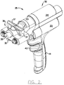
- FIG 2 is a perspective view of the dispenser 25 according to the present invention.
- the dispenser comprises a housing broadly designated at 32 , a motor 33 in the housing, a transmission 34 in the housing and driven by the motor, and a valving cartridge 35 in the housing 32 and driven by the transmission 34 for dispensing foamable compositions upon demand.
- the motor 33 is positioned below the valving cartridge 35 for providing a clear line of sight along the top of the housing. As can be understood with respect to Figure 1, such a clear line of sight is of significant advantage to an operator of the dispenser and the overall dispensing system.
- the valving cartridge 35 is readily and easily detachable from the valving clamp assembly 36 .
- the design and operation of detachment are described in commonly-assigned U.S. Patent No. 4,469,251 to Sperry et al. which is incorporated entirely herein by reference.
- the design and operation of the valving cartridge 35 are described in detail in commonly-assigned U.S. Patent No. 4,568,003 to Sperry et al. which is likewise incorporated entirely herein by reference.
- FIGS 2 and 3 illustrate that the dispenser 25 further comprises means shown as the valving clamp assembly 36 for delivering foam precursors to the valving cartridge 35 .
- the design and operation of the valving clamp assembly 36 are described in great detail in commonly-assigned U.S. Patent No. 5,215,226 to Bertram et al. which is incorporated entirely herein by reference.
- the cartridge 35 is typically designed to be removable from the valving clamp assembly 36 .
- the design of the clamp 36 requires that the handles 37 (and thus the flow of precursors) be turned off before the cartridge 35 can be removed. Alternatively, before fluids can flow back into the cartridge 35 , the clamp handles 37 must be rotated back into their clamping position.
- Figure 1 illustrates the hoses 24 connected to the dispenser 25 .
- the hoses are not shown in Figures 2 and 3 for the sake of clarity, but they connect to the rear portions of the valving clamp assembly 36 .
- the valving cartridge 35 further comprises a mixing chamber along with means for separately delivering two foam precursors to the mixing chamber.
- the mixing chamber and the entry ports to it are likewise discussed in significant detail in commonly-assigned U.S. Patent No. 5,186,905 to Bertram et al. which is likewise incorporated entirely herein by reference.
- the motor 33 is most preferably an electric motor, and indeed one of the advantages of the system is its potential for all-electric operation.
- a trigger 40 initiates the motor to drive the transmission 34 and the valving cartridge 35 .
- the housing 32 comprises an upper portion that extends generally longitudinally parallel to the axis of the valving cartridge 35 and a lower portion extending generally perpendicularly downwardly from the upper portion and forming a handle 41 for the housing 32 of the dispenser 25 .
- the housing 32 is preferably formed of an appropriate engineering plastic of which there are a number of appropriate selections.
- engineing plastic refers to polymers that exhibit "hardness, strength, machinability, dimensional stability, non-flammability and resistance to corrosion, most acids, solvents and heat.” Lewis, Hawley's Condensed Chemical Dictionary , 12th Ed. (1993).
- the housing 32 is formed of several pieces so that it can be quickly and easily replaced for service reasons without disassembling the entire dispenser. Taken together, Figures 2 and 3 illustrate that the rear portion of the housing 32 carries the motor 33 and the transmission 34 and form the backbone assembly of the dispenser 25 . Thus, the rear portion of the housing 32 conveniently contains most of the essential mechanical elements of the dispenser.
- the valving cartridge 35 is a cylinder with an axial valving rod 38 . Accordingly, in the preferred embodiment of the invention, the motor 33 is positioned below the longitudinal axis of the cylindrical valving cartridge.
- Figure 3 shows some additional details of the dispenser 25 with the housing 32 and some other features removed.
- Figure 3 illustrates an electrical power cord 42 and its appropriate connection to the rear of the dispenser 25 .
- the motor 33 is illustrated in more detail in Figures 3 and 4 which show that the functional portions of the transmission are rearward of the motor.
- Figure 3 also more clearly shows the relationship of the motor as being below the axis of the valving cartridge 35 .
- Figure 4 shows the motor 33 , a drive gear 43 , a driven gear 44 for the transmission 34 , which in turn drives another gear 45 on a composite shaft broadly designated at 46 .
- the shaft 46 is in turn attached to the valving cartridge 35 in a manner typical of these devices and which will not otherwise be described in detail.
- the overall dispensing system comprises a number of additional features.
- the system comprises the electronic controller 27 which is remote from the pump and remote from the dispenser.
- the controller will typically comprise a main board and a power management board.
- the main board is that portion of the circuitry which controls the electrical operation of the pumps, hoses, and dispenser.
- the power management board converts available electric power into the frequency and voltage required by the main board.
- Four power management boards are exemplary of this objective: single phase, 50 or 60 cycles (Hz), 170 to 265 volts (alternating current, "V ac "), and 30 amps (predominantly North America); three phase “delta” configuration, 50-60 Hz, 170 V ac phase to phase, 30 amps each phase (predominantly North America); three phase “delta” configuration, 50-60 Hz, 170 V ac phase to phase, 20 amps each phase (some areas in Europe); and three phase "Y” configuration, 50 or 60 Hz, 170-265 V ac , phase to neutral, 16 amps each phase (predominantly Europe, Pacific Rim, and Far East).
- the power management board distributes a specific electrical phase configuration into one standard configuration designed for the control board.
- the board controls portions of the dispenser and the pump, and also provides electric current to the hoses 24 for heating the hoses to maintain a foamable composition at an elevated temperature (and thus more fluid) in the hoses.
- the pumps 20 and 21 are typically electrically driven and electrically controlled, and thus the dispensing system includes the respective electric cables shown at 47 in Figure 1.
- the pumps 20 and 21 further comprise their own electronic pump controls.
- the extent to which the pump must be controlled by signals transmitted between the pumps 20 and 21 and the controller 27 are greatly reduced which in turn greatly reduces the radio frequency (RF) interference produced by signal traffic between the pumps 20 and 21 and the controller 27 .
- RF radio frequency
Landscapes
- Engineering & Computer Science (AREA)
- Mechanical Engineering (AREA)
- Containers And Packaging Bodies Having A Special Means To Remove Contents (AREA)
- Manufacture Of Porous Articles, And Recovery And Treatment Of Waste Products (AREA)
- Nozzles (AREA)
- Adhesives Or Adhesive Processes (AREA)
- Cosmetics (AREA)
- Basic Packing Technique (AREA)
- Confectionery (AREA)
- Vending Machines For Individual Products (AREA)
- Casting Or Compression Moulding Of Plastics Or The Like (AREA)
- Closures For Containers (AREA)
Claims (18)
- Handbetätigte Abgabevorrichtung (25) zum Abgeben von schäumbaren Zusammensetzungen, und die besonders für an Ort und Stelle geschäumte Verpackungssysteme nützlich ist, woibei die handbetätige Abgabevorrichtung folgendes umfasst:ein Gehäuse (32);einen Motor (33) in dem Gehäuse;eine Übersetzung (34) in dem Gehäuse, und die von dem Motor angetrieben wird; und eine Ventilkassette (35) in dem Gehäuse, und die von der Übersetzung angetrieben wird, um schäumbare Zusammensetzungen nach Bedarf abzugeben;
dadurch gekennzeichnet, dass der Motor unter der Ventilkassette angeordnet ist, um eine klare Sichtlinie entlang dem Oberteil des Gehäuses zu liefern. - Abgabevorrichtung nach Anspruch 1, in der die Ventilkassette (35) entfernbar an der Übersetzung (34) befestigt ist, und ein Klemmgerät (36) die Ventilkassette an dem Gehäuse befestigt.
- Abgabevorrichtung nach Anspruch 1 oder 2, in der die Ventilkasse4tte (35) eine Mischkammer einschließt, und ein Mittel geliefert ist, um zwei Schaumvorläufer getrennt an die Mischkammer zu liefern.
- Abgabevorrichtung nach Anspruch 1, 2 oder 3, in der der Motor einen elektrisachen Motor (33) umfasst, der von einem Auslöser (40) gesteuert ist.
- Abgabevorrichtung nach einem vorhergehenden Anspruch, in der das Gehäuse (32) aus einem Maschinenbaukunststoff gebildet ist, und ein oberes Teil umfasst, das sich im allgemeinen längs verlaufend parallel zu der Achse der Ventilkassette (35) erstreckt, und ein unteres Teil, das sich im allgemeinen senkrecht von dem oberen Teil nach unten erstreckt und einen Handgriff (41) für das Gehäuse und die Abgabevorrichtung bildet.
- Abgabevorrichtung nach einem vorhergehenden Anspruch in der die Ventilkassette (35) einen Zylinder mit einer axialen Ventilstange (38) umfasst, und der Motor (33) unter der längs verlaufenden Achse der zylindrischen Ventilkassette angeordnet ist.
- System zum Abgeben von schäumbaren Zusammensetzungen, das folgendes umfasst: eine handbetätigte Abgabevorrichtung (25) nach Anspruch 1;eine Pumpe (20, 21), um eine schäumbare Zusammensetzung von einem Vorrat zu der Abgabevorrichtung zu pumpen; undeinen Schlauch (24), der an der Pumpe angeschlossen ist, um schäumbare Zusammensetzungen von der Pumpe zu tragen.
- Abgabesystem nach Anspruch 7, das ein elektronisches Steuergerät (27) entfernt von der Pumpe (20, 21) und entfernt von der Abgabevorrichtung (25) einschließt.
- Abgabesystem nach Anspruch 8, in dem die Pumpe eine elektrisch angetriebene und elektronisch gesteuerte Pumpe (20, 21) umfasst, und elektrische Kabel (47) zwischen der Pumpe und dem Steuergerät (27) und zwischen dem Steuergerät und der handbetätigten Abgabevorrichtung (25) geliefert sind, um elektrische Steuersignale zwischen der Pumpe iund dem Steuergerät und zwischen dem Steuergerät und der Abgabevorrichtung zu senden.
- Abgabesystem nach Anspruch 9, in dem die Pumpe (20, 21) elektronische Pumpensteuerungen einschließt, um das Ausmaß zu verringern, auf das die Pumpe von Signalen gesteuert werden muss, die zwischen der Pumpe und dem Steuergerät (27) gesendet werden, und um ihrerseits die Radiofrequenz(rf)störung zu verringern, die von Signalverkehr zwischen der Pumpe und dem Steuergerät hergestellt wird.
- Abgabesystem nach einem vorhergehenden Anspruch 7 bis 10, in dem der Schlauch (24) ein Erwärmungsmittel einschließt, um eine schäumbare Zusammensetzung in einem flüssigen Zustand in dem Schlauch zu halten.
- Abgabesystem nach einem vorhergehenden Anspruch 7 bis 11, das zwei der Pumpen (20, 21) umfasst, um entsprechende Schaumvorläufer getrennt von getrennten Quellen (22, 23) zu der handbetätigten Abgabevorrichtung (25) zu pumpen, und zwei der Schläuche (24), einen von jeder Pumpe, um entsprechende Schaumvorläufer von den getrennten Quellen getrennt zu der handbetätigten Abgabevorrichtung zu tragen.
- Abgabesystem nach einem vorhergehenden Anspruch 8 bis 12, in dem das entfernte elektronische Steuergerät (27) eine Haupttafel und eine Leistungsverwaltungstafel umfasst.
- Abgabesystem nach Anspruch 13, in dem die Leistungsverwaltungstafel einphasig ist.
- Abgabesystem nach Anspruch 13, in dem die Leistungsverwaltungstafel dreiphasig ist.
- Abgabesystem nach Anspruch 13, in dem die Leistungsverwaltungstafel einen spezifischen elektrischen Phasenaufbau in einen Standardaufbau verteilt, der für die Steuertafel gestaltet ist.
- Abgabesystem nach einem vorhergehenden Anspruch 13 bis 16, in dem die Haupttafel Teile der Abgabevorrichtung und der Pumpe steuert.
- Abgabesystem nach einem vorhergehenden Anspruch 13 bis 17, in dem die Haupttafel einenm elektrischen Strom an den (die) Schlauch (Schläuche) (24) liefert, um den (die) Schlauch (Schläuche) zu erwärmen, um eine schäumbare Zusammensetzung auf einer angehobenen Temperatur in dem (den) Schlauch (Schläuchen) zu halten.
Applications Claiming Priority (3)
| Application Number | Priority Date | Filing Date | Title |
|---|---|---|---|
| US361322 | 1994-12-21 | ||
| US08/361,322 US5590816A (en) | 1994-12-21 | 1994-12-21 | Hand held dispenser for foamable compositions and dispensing system |
| PCT/US1995/016442 WO1996019329A1 (en) | 1994-12-21 | 1995-12-15 | Hand held dispenser for foamable compositions and dispensing system |
Publications (2)
| Publication Number | Publication Date |
|---|---|
| EP0799116A1 EP0799116A1 (de) | 1997-10-08 |
| EP0799116B1 true EP0799116B1 (de) | 1999-03-03 |
Family
ID=23421571
Family Applications (1)
| Application Number | Title | Priority Date | Filing Date |
|---|---|---|---|
| EP95943852A Expired - Lifetime EP0799116B1 (de) | 1994-12-21 | 1995-12-15 | Handbetätigte abgabevorrichtung für schäumbare zusammensetzungen und abgabesystem |
Country Status (15)
| Country | Link |
|---|---|
| US (2) | US5590816A (de) |
| EP (1) | EP0799116B1 (de) |
| JP (1) | JPH10511303A (de) |
| KR (1) | KR100393149B1 (de) |
| CN (1) | CN1064883C (de) |
| AT (1) | ATE177043T1 (de) |
| AU (1) | AU693316B2 (de) |
| BR (1) | BR9510370A (de) |
| DE (1) | DE69508114T2 (de) |
| ES (1) | ES2128115T3 (de) |
| FI (1) | FI972625L (de) |
| HU (1) | HUT77997A (de) |
| NO (1) | NO972851L (de) |
| PL (1) | PL179539B1 (de) |
| WO (1) | WO1996019329A1 (de) |
Families Citing this family (41)
| Publication number | Priority date | Publication date | Assignee | Title |
|---|---|---|---|---|
| US5590816A (en) * | 1994-12-21 | 1997-01-07 | Sealed Air Corporation | Hand held dispenser for foamable compositions and dispensing system |
| US6135327A (en) * | 1998-10-01 | 2000-10-24 | Mcneil (Ohio) Corporation | Battery operated grease gun |
| US6883563B2 (en) | 2001-07-26 | 2005-04-26 | Judson L. Smith | Apparatus and method to monitor the usage of a network system of personal hand sanitizing dispensers |
| US7597122B1 (en) | 2001-07-26 | 2009-10-06 | Smith Judson L | Apparatus and method to monitor the usage of a network system of personal hand sanitizing dispensers |
| US20030080203A1 (en) * | 2001-10-30 | 2003-05-01 | Jay Roth | Apparatus and method for combining liquids and fillers for spray application |
| US6704617B2 (en) | 2002-04-11 | 2004-03-09 | Flexible Products Company | Automated system for control and diagnostics for dispensing systems |
| EP1636658B1 (de) * | 2003-05-09 | 2009-04-15 | Intellipack, Inc. | System zur Steuerung und Fernüberwachung eines Schaumausgabeautomats |
| US7156260B2 (en) * | 2003-05-09 | 2007-01-02 | Intellipack | Mixing module drive mechanism and dispensing system with same |
| US7735685B2 (en) | 2003-05-09 | 2010-06-15 | Intellipack | Dispensing system with in line chemical pump system |
| US7341632B2 (en) | 2003-05-09 | 2008-03-11 | Intellipack | Dispensing system with means for easy access of dispenser components and method of using same |
| US7552847B2 (en) * | 2003-05-09 | 2009-06-30 | Intellipack | Dispenser mixing module and method of assembling and using same |
| US7182221B2 (en) * | 2003-05-09 | 2007-02-27 | Intellipack | Dispensing system and method of manufacturing and using same with a dispenser tip management |
| US20050033207A1 (en) * | 2003-08-04 | 2005-02-10 | 3Fi Products Llc | Immobilizing apparatus, and methods of use and manufacture |
| US7077636B2 (en) * | 2004-02-12 | 2006-07-18 | 3Fi Products Llc | Foam-in-place apparatus, and methods of use and manufacture |
| USD513058S1 (en) | 2004-03-12 | 2005-12-20 | Intellipack | Dispenser |
| WO2005090038A2 (en) * | 2004-03-12 | 2005-09-29 | Intellipack | Dispenser system with dispenser holster |
| WO2005090037A1 (en) * | 2004-03-12 | 2005-09-29 | Intellipack | Hand held dispenser |
| US6997319B2 (en) * | 2004-03-23 | 2006-02-14 | Sealed Air Corporation | Heat resistant foam-in-bag packaging |
| USD512648S1 (en) | 2004-12-15 | 2005-12-13 | Smith Judson L | Dispenser for fluid material |
| US20060210409A1 (en) * | 2005-03-15 | 2006-09-21 | Sumner William P | Grease pump |
| USD526100S1 (en) | 2005-05-05 | 2006-08-01 | Black & Decker Inc. | Hand-held scrubber |
| WO2006130818A2 (en) * | 2005-06-01 | 2006-12-07 | Pathways, Llc | Foam cushion forming apparatus and methods |
| US8444068B2 (en) | 2005-10-26 | 2013-05-21 | Techtronic Outdoor Products Technology Limited | Dual flow pressure washer |
| US7854398B2 (en) * | 2005-10-26 | 2010-12-21 | Techtronic Outdoor Products Technology Limited | Hand held pressure washer |
| US20070241852A1 (en) * | 2006-04-14 | 2007-10-18 | Goudreau Joel S | Transformer with foamed insulating material and method of manufacturing the same |
| US7731104B2 (en) * | 2006-04-26 | 2010-06-08 | Wagner Spray Tech Corporation | Texture sprayer |
| USD554741S1 (en) * | 2006-04-26 | 2007-11-06 | Wagner Spray Tech Corporation | Texture sprayer |
| US7937792B2 (en) * | 2006-10-19 | 2011-05-10 | Black & Decker Inc. | Pole scrubber |
| US20090101673A1 (en) * | 2007-10-17 | 2009-04-23 | Alioto George S | Motorized extrusion tool |
| US8425203B2 (en) * | 2008-04-25 | 2013-04-23 | Techtronic Outdoor Products Technology Limited | Portable pressure washer system |
| US8224481B2 (en) * | 2009-01-19 | 2012-07-17 | Access Business Group International Llc | Method and apparatus for dispensing fluid compositions |
| GB0915002D0 (en) * | 2009-08-28 | 2009-09-30 | 3M Innovative Properties Co | Device for dispensing a dental material |
| US11325286B2 (en) | 2009-09-24 | 2022-05-10 | Sealed Air Corporation (Us) | Mixing machine for producing foam within a bag |
| USD623267S1 (en) | 2009-10-30 | 2010-09-07 | Wagner Spray Tech Corporation | Texture sprayer |
| US9623622B2 (en) | 2010-02-24 | 2017-04-18 | Michael Baines | Packaging materials and methods |
| US9085002B2 (en) * | 2011-05-19 | 2015-07-21 | Illinois Tool Works Inc. | Modular manifold adhesive gun |
| US9242267B2 (en) | 2013-01-31 | 2016-01-26 | Owens Corning Intellectual Capital, Llc | Method and apparatus for mixing and applying material |
| CN106999881A (zh) | 2014-10-07 | 2017-08-01 | 捷通国际有限公司 | 个人配制装置 |
| WO2018112286A1 (en) | 2016-12-15 | 2018-06-21 | Sealed Air Corporation (Us) | Packaging method |
| US10898034B1 (en) | 2019-07-02 | 2021-01-26 | Armin Arminak | All plastic hand foam pump |
| EP4108405B1 (de) * | 2021-06-25 | 2024-09-25 | Storopack Hans Reichenecker GmbH | Maschine zur herstellung von füllschaumbeutel-packmaterial |
Family Cites Families (38)
| Publication number | Priority date | Publication date | Assignee | Title |
|---|---|---|---|---|
| NL280839A (de) * | 1961-07-19 | |||
| US3236419A (en) * | 1964-02-10 | 1966-02-22 | Continental Aviat & Eng Corp | Foam dispenser |
| US3687370A (en) * | 1971-01-18 | 1972-08-29 | Instapak Corp | Liquid mixing and dispensing apparatus |
| US4033481A (en) * | 1973-02-14 | 1977-07-05 | Artek Industries, Inc. | Liquid material-dispensing apparatus |
| US3837575A (en) * | 1973-08-27 | 1974-09-24 | Upjohn Co | Spray gun |
| US4117551A (en) * | 1974-05-30 | 1978-09-26 | William R. Brooks | Purgeable dispensing gun for polyurethane foam and the like |
| US4023733A (en) * | 1974-10-25 | 1977-05-17 | Instapak Corporation | Foam dispensing apparatus |
| US3945569A (en) * | 1974-10-25 | 1976-03-23 | Instapak Corporation | Foam dispensing apparatus |
| US4129231A (en) * | 1975-11-13 | 1978-12-12 | Jeddeloh Bros. Sweed Mills, Inc. | Portable, hand-held gun for dispensing multiple fluidic components to a mixer |
| US3984033A (en) * | 1975-12-29 | 1976-10-05 | Wear-Ever Aluminum, Inc. | Electric gun for dispensing of comestibles |
| US4159079A (en) * | 1977-08-24 | 1979-06-26 | Sealed Air Corporation | Dispenser |
| US4262847A (en) * | 1979-01-02 | 1981-04-21 | Witco Chemical Corporation | Urethane foam gun |
| US4426023A (en) * | 1981-03-06 | 1984-01-17 | Sealed Air Corporation | Cleaning assembly for a foam dispensing apparatus |
| US4568003A (en) * | 1981-09-02 | 1986-02-04 | Sealed Air Corporation | Detachable mixing chamber for a fluid dispensing apparatus |
| US4469251A (en) * | 1981-09-02 | 1984-09-04 | Sealed Air Corporation | Detachable mixing chamber for a fluid dispensing apparatus |
| US4440320A (en) * | 1981-11-30 | 1984-04-03 | Wernicke Steven A | Foam dispensing apparatus |
| FR2532561A1 (fr) * | 1982-09-06 | 1984-03-09 | Perette Jacques | Pistolet pneumatique pour la projection de mousse de polyurethane |
| FR2589784A2 (fr) * | 1982-09-23 | 1987-05-15 | Perette Jacques | Additif de remplacement de commande de marche et d'arret de fonctionnement de la centrale mobile en electro-mecanique pour la projection de mousse de polyurethane par des circuits de commande electronique |
| US4993596A (en) * | 1985-05-10 | 1991-02-19 | Insta-Foam Products Inc. | Mixing and dispensing gun with improved removal nozzle |
| US4708292A (en) * | 1985-06-05 | 1987-11-24 | Olin Corporation | Foam dispensing gun with improved mixing chamber |
| US4925107A (en) * | 1985-07-17 | 1990-05-15 | Insta-Foam Products, Inc. | Low cost mixing and dispensing gun for reactive chemical products |
| US4676437A (en) * | 1985-07-17 | 1987-06-30 | Insta-Foam Products, Inc. | Low cost mixing and dispensing gun for reactive chemical products |
| US4674268A (en) * | 1985-09-26 | 1987-06-23 | Sealed Air Corporation | Apparatus and method for forming foam cushions for packaging purposes |
| US4762253A (en) * | 1987-02-17 | 1988-08-09 | Rhh Enterprises, Inc. | Foam dispensing gun |
| US4854109A (en) * | 1988-08-22 | 1989-08-08 | Sealed Air | Apparatus and method for forming foam cushions for packaging purposes |
| US4800708A (en) * | 1987-11-16 | 1989-01-31 | Sealed Air Corporation | Apparatus and method for forming foam cushions for packaging purposes |
| US5005765A (en) * | 1988-01-25 | 1991-04-09 | Specified Equipment Systems Company, Inc. | Method and apparatus for applying multicomponent materials |
| US4913317A (en) * | 1988-09-14 | 1990-04-03 | Foamtek, Inc. | Foam dispensing apparatus |
| US5027975A (en) * | 1989-12-14 | 1991-07-02 | Keske David G | Urethane foam gun |
| US5050776A (en) * | 1990-01-02 | 1991-09-24 | Olin Corporation | Cartridge heater for foam dispensing apparatus |
| US5143296A (en) * | 1991-02-19 | 1992-09-01 | Pmc, Inc. | Pneumatic spray gun |
| US5242115A (en) * | 1991-04-22 | 1993-09-07 | Fomo Products, Inc. | Apparatus and method for mixing and dispensing and mixing nozzle therefore |
| US5129581A (en) * | 1991-05-01 | 1992-07-14 | Insta-Foam Products, Inc. | Nozzle for mixing and dispensing reduced CFC and non-CFC foams |
| US5186905A (en) * | 1991-07-16 | 1993-02-16 | Sealed Air Corporation | Cartridge port design for dispensing foam precursors |
| US5215226A (en) * | 1992-04-21 | 1993-06-01 | Sealed Air Corporation | Clamping system for fluid injection devices |
| US5265761A (en) * | 1992-07-10 | 1993-11-30 | Insta-Foam Products, Inc. | High performance foam dispensing gun |
| US5339991A (en) * | 1992-12-15 | 1994-08-23 | Foamseal, Inc. | Apparatus for applying a foamable resin |
| US5590816A (en) * | 1994-12-21 | 1997-01-07 | Sealed Air Corporation | Hand held dispenser for foamable compositions and dispensing system |
-
1994
- 1994-12-21 US US08/361,322 patent/US5590816A/en not_active Expired - Lifetime
-
1995
- 1995-12-15 DE DE69508114T patent/DE69508114T2/de not_active Expired - Lifetime
- 1995-12-15 PL PL95320917A patent/PL179539B1/pl not_active IP Right Cessation
- 1995-12-15 JP JP8519920A patent/JPH10511303A/ja active Pending
- 1995-12-15 FI FI972625A patent/FI972625L/fi unknown
- 1995-12-15 WO PCT/US1995/016442 patent/WO1996019329A1/en not_active Ceased
- 1995-12-15 CN CN951970259A patent/CN1064883C/zh not_active Expired - Fee Related
- 1995-12-15 EP EP95943852A patent/EP0799116B1/de not_active Expired - Lifetime
- 1995-12-15 AT AT95943852T patent/ATE177043T1/de not_active IP Right Cessation
- 1995-12-15 BR BR9510370A patent/BR9510370A/pt not_active IP Right Cessation
- 1995-12-15 HU HU9900083A patent/HUT77997A/hu unknown
- 1995-12-15 AU AU45220/96A patent/AU693316B2/en not_active Ceased
- 1995-12-15 ES ES95943852T patent/ES2128115T3/es not_active Expired - Lifetime
- 1995-12-15 KR KR1019970704202A patent/KR100393149B1/ko not_active Expired - Fee Related
-
1996
- 1996-07-15 US US08/680,371 patent/US5709317A/en not_active Expired - Lifetime
-
1997
- 1997-06-19 NO NO972851A patent/NO972851L/no not_active Application Discontinuation
Also Published As
| Publication number | Publication date |
|---|---|
| AU693316B2 (en) | 1998-06-25 |
| DE69508114T2 (de) | 1999-09-16 |
| NO972851D0 (no) | 1997-06-19 |
| US5709317A (en) | 1998-01-20 |
| HUT77997A (hu) | 1999-04-28 |
| EP0799116A1 (de) | 1997-10-08 |
| AU4522096A (en) | 1996-07-10 |
| ES2128115T3 (es) | 1999-05-01 |
| PL179539B1 (pl) | 2000-09-29 |
| FI972625A0 (fi) | 1997-06-18 |
| BR9510370A (pt) | 1998-06-02 |
| NO972851L (no) | 1997-07-29 |
| PL320917A1 (en) | 1997-11-10 |
| WO1996019329A1 (en) | 1996-06-27 |
| FI972625A7 (fi) | 1997-08-19 |
| US5590816A (en) | 1997-01-07 |
| CN1064883C (zh) | 2001-04-25 |
| DE69508114D1 (de) | 1999-04-08 |
| FI972625L (fi) | 1997-08-19 |
| CN1171075A (zh) | 1998-01-21 |
| JPH10511303A (ja) | 1998-11-04 |
| KR100393149B1 (ko) | 2004-07-16 |
| ATE177043T1 (de) | 1999-03-15 |
| MX9704624A (es) | 1997-09-30 |
Similar Documents
| Publication | Publication Date | Title |
|---|---|---|
| US5590816A (en) | Hand held dispenser for foamable compositions and dispensing system | |
| US5050776A (en) | Cartridge heater for foam dispensing apparatus | |
| KR100306970B1 (ko) | 백발포포장시스템 | |
| US4496081A (en) | Dispensing apparatus | |
| AU682974B2 (en) | Multi-component dispenser with self-pressurization system | |
| US7264178B1 (en) | Foam spraying rig | |
| US6629599B2 (en) | Foam in bag packaging system | |
| US20070045289A1 (en) | Portable spray system | |
| US5791522A (en) | Modular narrow profile foam dispenser | |
| CN101686695A (zh) | 用于具有增强的隔热特性的产品分配器的方法和装置 | |
| CA2894340C (en) | Adhesive applicator | |
| US20100219204A1 (en) | Insulated System for Dispensing a One-Component Polyurethane Foam | |
| WO2001024941A9 (en) | Portable tool box | |
| CA2208591C (en) | Hand held dispenser for foamable compositions and dispensing system | |
| US6272813B1 (en) | Foam in bag packaging system | |
| US3921279A (en) | Method for making a support for an object | |
| EP2759990A1 (de) | Fahrzeug für die Getränkezubereitung | |
| MXPA97004624A (en) | Manual distributor for foam compositions and distribui system | |
| US20170043362A1 (en) | Systems and Methods for Portable Multi-Component Mixing of Materials for Spray Application of Same | |
| EP1022104A1 (de) | Bewegbare Vorrichtung zum Austragen von Schaumstoff | |
| US20050236422A1 (en) | Portable apparatus for mixing and dispensing viscous materials | |
| EP1325801A1 (de) | Gegossene Gegenstände aus Kunststoff | |
| US4476076A (en) | Method of open forming an expanded polyester resin article involving a controlled induction period | |
| EP0072024A2 (de) | Formen von ungesättigten Polyestern | |
| US12109743B2 (en) | Polymer foam system and method |
Legal Events
| Date | Code | Title | Description |
|---|---|---|---|
| PUAI | Public reference made under article 153(3) epc to a published international application that has entered the european phase |
Free format text: ORIGINAL CODE: 0009012 |
|
| 17P | Request for examination filed |
Effective date: 19970707 |
|
| AK | Designated contracting states |
Kind code of ref document: A1 Designated state(s): AT BE CH DE DK ES FR GB GR IE IT LI LU MC NL PT SE |
|
| GRAG | Despatch of communication of intention to grant |
Free format text: ORIGINAL CODE: EPIDOS AGRA |
|
| 17Q | First examination report despatched |
Effective date: 19980223 |
|
| GRAG | Despatch of communication of intention to grant |
Free format text: ORIGINAL CODE: EPIDOS AGRA |
|
| GRAG | Despatch of communication of intention to grant |
Free format text: ORIGINAL CODE: EPIDOS AGRA |
|
| GRAH | Despatch of communication of intention to grant a patent |
Free format text: ORIGINAL CODE: EPIDOS IGRA |
|
| GRAH | Despatch of communication of intention to grant a patent |
Free format text: ORIGINAL CODE: EPIDOS IGRA |
|
| GRAA | (expected) grant |
Free format text: ORIGINAL CODE: 0009210 |
|
| AK | Designated contracting states |
Kind code of ref document: B1 Designated state(s): AT BE CH DE DK ES FR GB GR IE IT LI LU MC NL PT SE |
|
| PG25 | Lapsed in a contracting state [announced via postgrant information from national office to epo] |
Ref country code: GR Free format text: LAPSE BECAUSE OF NON-PAYMENT OF DUE FEES Effective date: 19990303 |
|
| REF | Corresponds to: |
Ref document number: 177043 Country of ref document: AT Date of ref document: 19990315 Kind code of ref document: T |
|
| REG | Reference to a national code |
Ref country code: CH Ref legal event code: EP |
|
| REG | Reference to a national code |
Ref country code: IE Ref legal event code: FG4D |
|
| REF | Corresponds to: |
Ref document number: 69508114 Country of ref document: DE Date of ref document: 19990408 |
|
| REG | Reference to a national code |
Ref country code: ES Ref legal event code: FG2A Ref document number: 2128115 Country of ref document: ES Kind code of ref document: T3 |
|
| ITF | It: translation for a ep patent filed | ||
| PG25 | Lapsed in a contracting state [announced via postgrant information from national office to epo] |
Ref country code: DK Free format text: LAPSE BECAUSE OF FAILURE TO SUBMIT A TRANSLATION OF THE DESCRIPTION OR TO PAY THE FEE WITHIN THE PRESCRIBED TIME-LIMIT Effective date: 19990603 |
|
| PG25 | Lapsed in a contracting state [announced via postgrant information from national office to epo] |
Ref country code: PT Free format text: LAPSE BECAUSE OF FAILURE TO SUBMIT A TRANSLATION OF THE DESCRIPTION OR TO PAY THE FEE WITHIN THE PRESCRIBED TIME-LIMIT Effective date: 19990604 |
|
| ET | Fr: translation filed | ||
| REG | Reference to a national code |
Ref country code: CH Ref legal event code: NV Representative=s name: KIRKER & CIE SA |
|
| PG25 | Lapsed in a contracting state [announced via postgrant information from national office to epo] |
Ref country code: LU Free format text: LAPSE BECAUSE OF NON-PAYMENT OF DUE FEES Effective date: 19991215 |
|
| PLBE | No opposition filed within time limit |
Free format text: ORIGINAL CODE: 0009261 |
|
| STAA | Information on the status of an ep patent application or granted ep patent |
Free format text: STATUS: NO OPPOSITION FILED WITHIN TIME LIMIT |
|
| 26N | No opposition filed | ||
| PG25 | Lapsed in a contracting state [announced via postgrant information from national office to epo] |
Ref country code: MC Free format text: LAPSE BECAUSE OF NON-PAYMENT OF DUE FEES Effective date: 20000630 |
|
| REG | Reference to a national code |
Ref country code: GB Ref legal event code: IF02 |
|
| PGFP | Annual fee paid to national office [announced via postgrant information from national office to epo] |
Ref country code: SE Payment date: 20021204 Year of fee payment: 8 |
|
| PGFP | Annual fee paid to national office [announced via postgrant information from national office to epo] |
Ref country code: AT Payment date: 20021211 Year of fee payment: 8 |
|
| PGFP | Annual fee paid to national office [announced via postgrant information from national office to epo] |
Ref country code: CH Payment date: 20021217 Year of fee payment: 8 |
|
| PGFP | Annual fee paid to national office [announced via postgrant information from national office to epo] |
Ref country code: IE Payment date: 20021223 Year of fee payment: 8 |
|
| PG25 | Lapsed in a contracting state [announced via postgrant information from national office to epo] |
Ref country code: IE Free format text: LAPSE BECAUSE OF NON-PAYMENT OF DUE FEES Effective date: 20031215 Ref country code: AT Free format text: LAPSE BECAUSE OF NON-PAYMENT OF DUE FEES Effective date: 20031215 |
|
| PG25 | Lapsed in a contracting state [announced via postgrant information from national office to epo] |
Ref country code: SE Free format text: LAPSE BECAUSE OF NON-PAYMENT OF DUE FEES Effective date: 20031216 |
|
| PG25 | Lapsed in a contracting state [announced via postgrant information from national office to epo] |
Ref country code: LI Free format text: LAPSE BECAUSE OF NON-PAYMENT OF DUE FEES Effective date: 20031231 Ref country code: CH Free format text: LAPSE BECAUSE OF NON-PAYMENT OF DUE FEES Effective date: 20031231 |
|
| EUG | Se: european patent has lapsed | ||
| REG | Reference to a national code |
Ref country code: CH Ref legal event code: PL |
|
| REG | Reference to a national code |
Ref country code: IE Ref legal event code: MM4A |
|
| PGFP | Annual fee paid to national office [announced via postgrant information from national office to epo] |
Ref country code: NL Payment date: 20081223 Year of fee payment: 14 |
|
| PGFP | Annual fee paid to national office [announced via postgrant information from national office to epo] |
Ref country code: BE Payment date: 20090202 Year of fee payment: 14 |
|
| BERE | Be: lapsed |
Owner name: *SEALED AIR CORP. Effective date: 20091231 |
|
| REG | Reference to a national code |
Ref country code: NL Ref legal event code: V1 Effective date: 20100701 |
|
| PG25 | Lapsed in a contracting state [announced via postgrant information from national office to epo] |
Ref country code: NL Free format text: LAPSE BECAUSE OF NON-PAYMENT OF DUE FEES Effective date: 20100701 Ref country code: BE Free format text: LAPSE BECAUSE OF NON-PAYMENT OF DUE FEES Effective date: 20091231 |
|
| PGFP | Annual fee paid to national office [announced via postgrant information from national office to epo] |
Ref country code: ES Payment date: 20141226 Year of fee payment: 20 Ref country code: GB Payment date: 20141229 Year of fee payment: 20 |
|
| PGFP | Annual fee paid to national office [announced via postgrant information from national office to epo] |
Ref country code: FR Payment date: 20141217 Year of fee payment: 20 |
|
| PGFP | Annual fee paid to national office [announced via postgrant information from national office to epo] |
Ref country code: IT Payment date: 20141224 Year of fee payment: 20 Ref country code: DE Payment date: 20141230 Year of fee payment: 20 |
|
| REG | Reference to a national code |
Ref country code: DE Ref legal event code: R071 Ref document number: 69508114 Country of ref document: DE |
|
| REG | Reference to a national code |
Ref country code: GB Ref legal event code: PE20 Expiry date: 20151214 |
|
| PG25 | Lapsed in a contracting state [announced via postgrant information from national office to epo] |
Ref country code: GB Free format text: LAPSE BECAUSE OF EXPIRATION OF PROTECTION Effective date: 20151214 |
|
| REG | Reference to a national code |
Ref country code: ES Ref legal event code: FD2A Effective date: 20160329 |
|
| PG25 | Lapsed in a contracting state [announced via postgrant information from national office to epo] |
Ref country code: ES Free format text: LAPSE BECAUSE OF EXPIRATION OF PROTECTION Effective date: 20151216 |