EP0798513B1 - Rohrabschnitt eines doppelwandigen Kaminrohrs für den Schornsteinbau - Google Patents
Rohrabschnitt eines doppelwandigen Kaminrohrs für den Schornsteinbau Download PDFInfo
- Publication number
- EP0798513B1 EP0798513B1 EP97102961A EP97102961A EP0798513B1 EP 0798513 B1 EP0798513 B1 EP 0798513B1 EP 97102961 A EP97102961 A EP 97102961A EP 97102961 A EP97102961 A EP 97102961A EP 0798513 B1 EP0798513 B1 EP 0798513B1
- Authority
- EP
- European Patent Office
- Prior art keywords
- pipe
- conically
- insulation
- inner pipe
- pipe section
- Prior art date
- Legal status (The legal status is an assumption and is not a legal conclusion. Google has not performed a legal analysis and makes no representation as to the accuracy of the status listed.)
- Expired - Lifetime
Links
- 238000009413 insulation Methods 0.000 claims abstract description 37
- 230000007704 transition Effects 0.000 claims abstract description 5
- 238000004519 manufacturing process Methods 0.000 claims description 4
- 238000010276 construction Methods 0.000 claims description 3
- 229910052500 inorganic mineral Inorganic materials 0.000 claims description 3
- 239000011707 mineral Substances 0.000 claims description 3
- 230000014759 maintenance of location Effects 0.000 claims 1
- 239000011324 bead Substances 0.000 description 1
- 230000004858 capillary barrier Effects 0.000 description 1
- 238000009434 installation Methods 0.000 description 1
- 238000000034 method Methods 0.000 description 1
- 229910001220 stainless steel Inorganic materials 0.000 description 1
- 239000010935 stainless steel Substances 0.000 description 1
Images
Classifications
-
- F—MECHANICAL ENGINEERING; LIGHTING; HEATING; WEAPONS; BLASTING
- F23—COMBUSTION APPARATUS; COMBUSTION PROCESSES
- F23J—REMOVAL OR TREATMENT OF COMBUSTION PRODUCTS OR COMBUSTION RESIDUES; FLUES
- F23J13/00—Fittings for chimneys or flues
- F23J13/04—Joints; Connections
-
- F—MECHANICAL ENGINEERING; LIGHTING; HEATING; WEAPONS; BLASTING
- F23—COMBUSTION APPARATUS; COMBUSTION PROCESSES
- F23J—REMOVAL OR TREATMENT OF COMBUSTION PRODUCTS OR COMBUSTION RESIDUES; FLUES
- F23J2213/00—Chimneys or flues
- F23J2213/20—Joints; Connections
- F23J2213/202—Joints; Connections between duct or stack sections
-
- F—MECHANICAL ENGINEERING; LIGHTING; HEATING; WEAPONS; BLASTING
- F23—COMBUSTION APPARATUS; COMBUSTION PROCESSES
- F23J—REMOVAL OR TREATMENT OF COMBUSTION PRODUCTS OR COMBUSTION RESIDUES; FLUES
- F23J2213/00—Chimneys or flues
- F23J2213/40—Heat insulation fittings
Definitions
- the invention relates to a pipe section of a double-walled chimney pipe for chimney construction, with a cylindrical inner tube, the one has an enlarged end, with a cylindrical outer tube, which is an enlarged End, and with one between the inner tube and outer tube arranged insulation.
- the invention also relates to a method for Production of such a pipe section.
- the pipe sections When creating chimneys on the outside of a building successively placed pipe sections on top of each other, the pipe sections be inserted into one another and the plug connection with an outside around the Pipe sections laid clamping band or a clamp is secured.
- the enlarged ends of the cylindrical inner tube and the cylindrical Outer tube are sleeve-like and arranged so that in Area of each end face of the pipe section is an expanded end.
- the insulation extends in the axial direction from the end face the extended end of the outer tube to the area where the Inner tube merges into its enlarged end, so that a between the enlarged end of the inner tube and the cylindrical part of the outer tube formed annulus is free of insulation. That's why the Interlocking adjacent pipe sections the extended end of the Inner pipe into the insulation of the next pipe section.
- the object of the invention is to provide a pipe section from which have gas and condensate-tight chimney pipes created with simple installation.
- the pipe sections should be easy to manufacture.
- the insulation extends from the end face of the tube section with a conically tapered outer tube and a flared inner tube to the transition region between the inner tube and its tapered end or the outer tube and its flared end.
- the insulation can consist of prefabricated mineral partial shells with a density of approx. 120 kg / m 3 and a compressive strength of approx. 10 kN / m 2 .
- the partial shells are sawn or milled from a prefabricated body, so that the inner diameter of the partial shells corresponds to the outer diameter of the inner tube and the outer diameter of the partial shells corresponds to the inner diameter of the outer tube.
- the invention also relates to a method for producing such Pipe section, wherein the inner tube with its tapered end in a base body is set, which is in the level of the transition area from Inner tube to its tapered end is a support surface for insulation has, then the insulation on the support surface and outside is placed against and held against the inner tube, and then the outer tube with its conically widened end on the free face of the inner tube and the insulation put on and over the inner tube and Insulation is pushed.
- the insulation is there not damaged because the flared end of the outer tube is like a Funnel acts by resiliently deforming the insulation, so that after the outer tube has been pushed all the way between Outer tube and inner tube formed fill again and a sufficient forms a firm connection between the outer tube and inner tube.
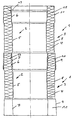
- the double-walled chimney pipe shown is intended for chimney construction. It consists of several pipe sections 1 arranged one behind the other, of which only two pipe sections are shown. Each pipe section 1 has an inner pipe 2 and an outer pipe 3 arranged concentrically thereto, and an insulation 4 arranged between inner pipe 2 and outer pipe 3.
- the tubes are made of stainless steel.
- the insulation consists of prefabricated mineral partial shells, not shown in detail, with a density of approx. 120 kg / m 3 and a compressive strength of approx. 10 kN / m 2 .
- the inner tube 2 has a widened compared to its cylinder part 5. flared end 6 and one opposite its cylinder part likewise widened, tapered end 7.
- the outer tube 3 has a widened compared to its cylinder part 8, flared end 9 and one opposite its cylinder part likewise widened, conically tapering end 10.
- the conical Ends 6, 7 and 9, 10 each have the same cone angle in the area between 0.5 ° and 2 °.
- the tapered ends 7, 10 have over their length has a diameter that is greater than the diameter of their associated one Cylinder parts 5 and 8. Because all ends 6, 7 and 8, 9 are the same Have cone angles and expanded compared to their cylinder parts 5 and 8 they can be made using the same tools and with great precision, in particular with identical cone angles.
- the procedure is such that the inner pipe 2 with its tapered end 7 placed in a base body e.g. an annular space 11 recognizable in the figure below the conically tapered end 7 of the inner tube 2 and the conically widened Fills end 9 of the outer tube 3 and a support surface for the insulation 4 owns.
- the Partial shells of insulation 4 not shown, are placed and held on.
- the outer tube 3 with its conically widened End 9 placed on the free end face of the inner tube 2 and the insulation 4 and pushed over the inner tube 2 and the insulation 4. there the insulation 4 is resiliently deformed at least in some areas. If the outer tube 3 is pushed completely over the inner tube 2, the insulation 4 adapts to the contours of the inner tube 2 and outer tube 3 and forms a sufficiently firm connection between the inner tube 2 and Outer tube 3, the annular space 11 remaining free of insulation.
- the pipe sections 1 are successively placed on top of each other, each with an annular body 12 in the Annulus 11 of the adjacent pipe section engages. Center it the pipe sections 1 against each other automatically and arise because of the small cone angle sufficient holding forces so that the connection between neighboring pipe sections 1 not by additional measures, e.g. Clamping straps or clamps that need to be secured.
- the flared end 6 of the inner tube 3 has a circumferential, after outside bead 13, which acts as a capillary barrier or moisture collector for condensates, which then do not penetrate to the insulation can.
Landscapes
- Engineering & Computer Science (AREA)
- Mechanical Engineering (AREA)
- General Engineering & Computer Science (AREA)
- Thermal Insulation (AREA)
- Rigid Pipes And Flexible Pipes (AREA)
- Chimneys And Flues (AREA)
- Working Measures On Existing Buildindgs (AREA)
- Incineration Of Waste (AREA)
- Rod-Shaped Construction Members (AREA)
Description
Claims (6)
- Rohrabschnitt eines doppelwandigen Kaminrohrs für den Schornsteinbau, mit einem zylindrischen Innenrohr, das ein erweitertes Ende aufweist, mit einem zylindrischen Außenrohr, das ein erweitertes Ende aufweist, und mit einer zwischen Innenrohr und Außenrohr angeordneten Isolierung, dadurch gekennzeichnet, daß sowohl das Innenrohr (2) als auch das Außenrohr (3) ein aufgeweitetes, sich konisch erweiterndes Ende (6 bzw. 9) und ein aufgeweitetes, sich konisch verjüngendes Ende (7 bzw. 10) aufweist, daß die konischen Enden (6, 7, 9, 10) gleiche, kleine Konuswinkel aufweisen, die hinreichend große Haltekräfte sowie Gas- und Kondensatdichtigkeit zwischen benachbarten Rohrabschnitten gewährleisten, und die konisch verjüngten Enden (7, 10) über ihre Länge größere Durchmesser aufweisen als die Zylinderteile (5, 8) von Innenrohr (2) bzw. Außenrohr (3), daß im Bereich jeder Stirnseite des Rohrabschnitts (1) ein konisch verjüngtes Ende (7 bzw. 10) sowie ein konisch erweitertes Ende (6 bzw. 9) angeordnet ist, und daß ein zwischen dem konisch verjüngten Ende (7) des Innenrohrs (2) und dem konisch erweiterten Ende (9) des Außenrohrs (3) gebildeter Ringraum (11) frei von Isolierung ist.
- Rohrabschnitt nach Anspruch 1, dadurch gekennzeichnet, daß der Konuswinkel 0,5° bis 2° beträgt.
- Rohrabschnitt nach einem der Ansprüche 1 oder 2, dadurch gekennzeichnet, daß die Länge der konischen Enden (6, 7, 9, 10) bei Rohrdurchmessern von bis zu 1.000 mm wenigstens 60 mm beträgt.
- Rohrabschnitt nach einem der Ansprüche 1 bis 3, dadurch gekennzeichnet, daß die Isolierung (4) sich von der Stirnseite des Rohrabschnitts (1) mit konisch verjüngtem Außenrohr (3) und konisch erweitertem Innenrohr (2) bis zum Übergangsbereich zwischen Innenrohr(2) und seinem konisch verjüngten Ende (7) bzw. dem Außenrohr (3) und seinem konisch erweiterten Ende (9) erstreckt.
- Rohrabschnitt nach einem der Ansprüche 1 bis 4, dadurch gekennzeichnet, daß die Isolierung aus vorgefertigten mineralischen Teilschalen mit einem Raumgewicht von ca. 120 kg/m3 und einer Druckfestigkeit von ca. 10 kN/m2 besteht.
- Verfahren zum Herstellen eines Rohrabschnitts nach einem der Ansprüche 1 bis 5, dadurch gekennzeichnet , daß das Innenrohr (2) mit seinem konisch verjüngten Ende(7) in einen Sockelkörper gesetzt wird, der in Höhe des Übergangsbereiches vom Innenrohr (2) zu seinem konisch verjüngten Ende (7) eine Stützfläche für die Isolierung (4) aufweist, daß die Isolierung (4) auf die Stützfläche und außen gegen das Innenrohr (2) gesetzt sowie daran gehalten wird und daß das Außenrohr (3) mit seinem konisch erweiterten Ende (9) auf die freie Stirnseite des Innenrohrs (2) und der Isolierung (4) aufgesetzt sowie über das Innenrohr (2) und die Isolierung (4) geschoben wird.
Applications Claiming Priority (2)
| Application Number | Priority Date | Filing Date | Title |
|---|---|---|---|
| DE19611580A DE19611580C1 (de) | 1996-03-23 | 1996-03-23 | Rohrabschnitt eines doppelwandigen Kaminrohrs für den Schornsteinbau |
| DE19611580 | 1996-03-23 |
Publications (3)
| Publication Number | Publication Date |
|---|---|
| EP0798513A2 EP0798513A2 (de) | 1997-10-01 |
| EP0798513A3 EP0798513A3 (de) | 1999-02-03 |
| EP0798513B1 true EP0798513B1 (de) | 2002-07-17 |
Family
ID=7789242
Family Applications (1)
| Application Number | Title | Priority Date | Filing Date |
|---|---|---|---|
| EP97102961A Expired - Lifetime EP0798513B1 (de) | 1996-03-23 | 1997-02-24 | Rohrabschnitt eines doppelwandigen Kaminrohrs für den Schornsteinbau |
Country Status (8)
| Country | Link |
|---|---|
| EP (1) | EP0798513B1 (de) |
| AT (1) | ATE220781T1 (de) |
| CZ (1) | CZ287333B6 (de) |
| DE (2) | DE19611580C1 (de) |
| DK (1) | DK0798513T3 (de) |
| ES (1) | ES2180832T3 (de) |
| HU (1) | HU224184B1 (de) |
| SI (1) | SI0798513T1 (de) |
Cited By (2)
| Publication number | Priority date | Publication date | Assignee | Title |
|---|---|---|---|---|
| EP1413828A2 (de) | 2002-10-25 | 2004-04-28 | Joseph Raab GmbH & Cie. KG | Abgasanlage und Verfahren zum Betreiben eines doppelwandigen Kaminrohrsystems |
| EP1431659A1 (de) * | 2002-12-21 | 2004-06-23 | eka edelstahlkamine gmbh | Stecksystem für Rohrverbindungen mit nichtlinearen kontinuierlichen Abschnitten |
Families Citing this family (7)
| Publication number | Priority date | Publication date | Assignee | Title |
|---|---|---|---|---|
| DE19547677C2 (de) * | 1995-12-20 | 2000-01-27 | Karl Schraeder Nachf Inh Karl | Kaminrohr für die Schornsteinsanierung |
| DE19825477C2 (de) * | 1998-06-08 | 2003-03-27 | Ct Therm Abgastechnik Gmbh | Außenwandkamin |
| DE19909787A1 (de) * | 1999-03-05 | 2000-09-07 | Wilfried Seitz | Schornsteindämmschale aus Mineralwolle und Verfahren zu deren Herstellung |
| DE20206239U1 (de) | 2002-04-19 | 2002-09-19 | Armacell Enterprise GmbH, 48153 Münster | Ummantelung für Isolierungen aus Edelstahlblech |
| EP2682660B1 (de) * | 2012-07-03 | 2015-04-22 | BEZA S.p.A. | Konische Fassung für Metallblechleitungen |
| DE202013002004U1 (de) | 2013-03-04 | 2013-04-24 | Jeremias GmbH Fachgroßhandel für Schornsteinbedarf | Kaminrohr sowie Abgasanlage mit einem solchen Kaminrohr |
| EP2871416A1 (de) * | 2013-11-06 | 2015-05-13 | eka edelstahlkamine gmbh | Adapterrohr für Rohrelement mit variabler Länge |
Family Cites Families (3)
| Publication number | Priority date | Publication date | Assignee | Title |
|---|---|---|---|---|
| US1272503A (en) * | 1917-01-16 | 1918-07-16 | Alice C Nelson | Chimney-flue. |
| DE2262668A1 (de) * | 1972-12-21 | 1974-06-27 | Plein Wagner Soehne | Aus mehreren aufeinandersetzbaren, rohrfoermigen abschnitten bestehender schornstein |
| FR2613746B1 (fr) * | 1987-04-10 | 1992-10-09 | Urion Daniel | Element de conduit de fumee etanche, a double paroi et calorifuge |
-
1996
- 1996-03-23 DE DE19611580A patent/DE19611580C1/de not_active Expired - Fee Related
-
1997
- 1997-02-24 DE DE59707701T patent/DE59707701D1/de not_active Expired - Lifetime
- 1997-02-24 AT AT97102961T patent/ATE220781T1/de active
- 1997-02-24 EP EP97102961A patent/EP0798513B1/de not_active Expired - Lifetime
- 1997-02-24 SI SI9730400T patent/SI0798513T1/xx unknown
- 1997-02-24 DK DK97102961T patent/DK0798513T3/da active
- 1997-02-24 ES ES97102961T patent/ES2180832T3/es not_active Expired - Lifetime
- 1997-03-20 CZ CZ1997863A patent/CZ287333B6/cs not_active IP Right Cessation
- 1997-03-21 HU HU9700625A patent/HU224184B1/hu active IP Right Grant
Cited By (2)
| Publication number | Priority date | Publication date | Assignee | Title |
|---|---|---|---|---|
| EP1413828A2 (de) | 2002-10-25 | 2004-04-28 | Joseph Raab GmbH & Cie. KG | Abgasanlage und Verfahren zum Betreiben eines doppelwandigen Kaminrohrsystems |
| EP1431659A1 (de) * | 2002-12-21 | 2004-06-23 | eka edelstahlkamine gmbh | Stecksystem für Rohrverbindungen mit nichtlinearen kontinuierlichen Abschnitten |
Also Published As
| Publication number | Publication date |
|---|---|
| CZ287333B6 (en) | 2000-10-11 |
| ES2180832T3 (es) | 2003-02-16 |
| DE19611580C1 (de) | 1997-10-30 |
| HU9700625D0 (en) | 1997-05-28 |
| DK0798513T3 (da) | 2002-10-14 |
| SI0798513T1 (en) | 2002-12-31 |
| ATE220781T1 (de) | 2002-08-15 |
| DE59707701D1 (de) | 2002-08-22 |
| EP0798513A2 (de) | 1997-10-01 |
| EP0798513A3 (de) | 1999-02-03 |
| CZ86397A3 (en) | 1997-10-15 |
| HUP9700625A3 (en) | 1998-10-28 |
| HU224184B1 (hu) | 2005-06-28 |
| HUP9700625A2 (hu) | 1998-03-30 |
Similar Documents
| Publication | Publication Date | Title |
|---|---|---|
| DE4028449C1 (de) | ||
| EP2873786B1 (de) | DOPPELWANDIGES GROßROHR, VERWENDUNG UND VERFAHREN ZUR HERSTELLUNG EINES DOPPELWANDIGEN GROßROHRS | |
| EP0798513B1 (de) | Rohrabschnitt eines doppelwandigen Kaminrohrs für den Schornsteinbau | |
| DE4000654C2 (de) | ||
| WO2020148065A1 (de) | Tragstruktur für eine windkraftanlage | |
| DE2637726C3 (de) | Streckenausbaurahmen | |
| DE19547677C2 (de) | Kaminrohr für die Schornsteinsanierung | |
| DE7718119U1 (de) | Mehrteilige leuchte, insbesondere aussenleuchte | |
| EP0098236B1 (de) | Lösbare rohrförmige Klemme zum Verbinden von zylindrischen Rohren | |
| CH671619A5 (de) | ||
| DE19800512C2 (de) | Muffensteckverbindung für Rohre, insbesondere Abgas- und Kaminrohre | |
| DE19859859A1 (de) | Modulgerüstrohr | |
| DE8606323U1 (de) | Mehrschaliger Kamin | |
| DE2016440C3 (de) | Rohrverbindung | |
| DE2233102A1 (de) | Rohrverbindung sowie verfahren und verbindungshuelse zur herstellung der rohrverbindung | |
| DE29806952U1 (de) | Abstandshalter für Kamineinsatzrohr | |
| DE3941247C2 (de) | ||
| DE3735507C1 (en) | Pipe | |
| DE202013002004U1 (de) | Kaminrohr sowie Abgasanlage mit einem solchen Kaminrohr | |
| DE69401629T2 (de) | Mehrzweckdichtung für Kontrollschacht | |
| DE8029823U1 (de) | Muffe aus gusseisen fuer das dichte zusammenfuegen zweier roehrenfoermiger elemente | |
| DE29522126U1 (de) | Kaminrohr für die Schornsteinsanierung | |
| EP1270871B1 (de) | Tübbing, Tübbingring und Tunnelausbau | |
| DE4332007A1 (de) | Vorrichtung zum Ausgleichen von Rohrleitungslängen | |
| DE3705683A1 (de) | Dichtring, vorzugsweise fuer kabelkanalrohre oder dergl. |
Legal Events
| Date | Code | Title | Description |
|---|---|---|---|
| PUAI | Public reference made under article 153(3) epc to a published international application that has entered the european phase |
Free format text: ORIGINAL CODE: 0009012 |
|
| AK | Designated contracting states |
Kind code of ref document: A2 Designated state(s): AT BE CH DE DK ES FI FR GB IE IT LI LU NL SE |
|
| AX | Request for extension of the european patent |
Free format text: LT PAYMENT 970303;LV PAYMENT 970303;SI PAYMENT 970303 |
|
| PUAL | Search report despatched |
Free format text: ORIGINAL CODE: 0009013 |
|
| AK | Designated contracting states |
Kind code of ref document: A3 Designated state(s): AT BE CH DE DK ES FI FR GB IE IT LI LU NL SE |
|
| AX | Request for extension of the european patent |
Free format text: LT PAYMENT 970303;LV PAYMENT 970303;SI PAYMENT 970303 |
|
| 17P | Request for examination filed |
Effective date: 19990112 |
|
| 17Q | First examination report despatched |
Effective date: 20010402 |
|
| GRAG | Despatch of communication of intention to grant |
Free format text: ORIGINAL CODE: EPIDOS AGRA |
|
| GRAG | Despatch of communication of intention to grant |
Free format text: ORIGINAL CODE: EPIDOS AGRA |
|
| GRAH | Despatch of communication of intention to grant a patent |
Free format text: ORIGINAL CODE: EPIDOS IGRA |
|
| GRAH | Despatch of communication of intention to grant a patent |
Free format text: ORIGINAL CODE: EPIDOS IGRA |
|
| GRAH | Despatch of communication of intention to grant a patent |
Free format text: ORIGINAL CODE: EPIDOS IGRA |
|
| GRAH | Despatch of communication of intention to grant a patent |
Free format text: ORIGINAL CODE: EPIDOS IGRA |
|
| GRAA | (expected) grant |
Free format text: ORIGINAL CODE: 0009210 |
|
| AK | Designated contracting states |
Kind code of ref document: B1 Designated state(s): AT BE CH DE DK ES FI FR GB IE IT LI LU NL SE |
|
| AX | Request for extension of the european patent |
Free format text: LT PAYMENT 19970303;LV PAYMENT 19970303;SI PAYMENT 19970303 |
|
| REF | Corresponds to: |
Ref document number: 220781 Country of ref document: AT Date of ref document: 20020815 Kind code of ref document: T |
|
| REG | Reference to a national code |
Ref country code: GB Ref legal event code: FG4D Free format text: NOT ENGLISH |
|
| REG | Reference to a national code |
Ref country code: CH Ref legal event code: EP |
|
| REG | Reference to a national code |
Ref country code: IE Ref legal event code: FG4D Free format text: GERMAN |
|
| REF | Corresponds to: |
Ref document number: 59707701 Country of ref document: DE Date of ref document: 20020822 |
|
| REG | Reference to a national code |
Ref country code: DK Ref legal event code: T3 |
|
| ET | Fr: translation filed | ||
| GBT | Gb: translation of ep patent filed (gb section 77(6)(a)/1977) |
Effective date: 20021128 |
|
| REG | Reference to a national code |
Ref country code: ES Ref legal event code: FG2A Ref document number: 2180832 Country of ref document: ES Kind code of ref document: T3 |
|
| PLBE | No opposition filed within time limit |
Free format text: ORIGINAL CODE: 0009261 |
|
| STAA | Information on the status of an ep patent application or granted ep patent |
Free format text: STATUS: NO OPPOSITION FILED WITHIN TIME LIMIT |
|
| 26N | No opposition filed |
Effective date: 20030422 |
|
| REG | Reference to a national code |
Ref country code: SI Ref legal event code: IF |
|
| REG | Reference to a national code |
Ref country code: FR Ref legal event code: PLFP Year of fee payment: 20 |
|
| PGFP | Annual fee paid to national office [announced via postgrant information from national office to epo] |
Ref country code: LU Payment date: 20160223 Year of fee payment: 20 |
|
| PGFP | Annual fee paid to national office [announced via postgrant information from national office to epo] |
Ref country code: CH Payment date: 20160222 Year of fee payment: 20 Ref country code: ES Payment date: 20160223 Year of fee payment: 20 Ref country code: IE Payment date: 20160218 Year of fee payment: 20 Ref country code: DK Payment date: 20160222 Year of fee payment: 20 Ref country code: IT Payment date: 20160222 Year of fee payment: 20 Ref country code: DE Payment date: 20160115 Year of fee payment: 20 |
|
| PGFP | Annual fee paid to national office [announced via postgrant information from national office to epo] |
Ref country code: AT Payment date: 20160218 Year of fee payment: 20 Ref country code: GB Payment date: 20160222 Year of fee payment: 20 Ref country code: FR Payment date: 20160222 Year of fee payment: 20 Ref country code: FI Payment date: 20160218 Year of fee payment: 20 Ref country code: SE Payment date: 20160222 Year of fee payment: 20 Ref country code: NL Payment date: 20160222 Year of fee payment: 20 Ref country code: BE Payment date: 20160222 Year of fee payment: 20 |
|
| REG | Reference to a national code |
Ref country code: DE Ref legal event code: R071 Ref document number: 59707701 Country of ref document: DE |
|
| REG | Reference to a national code |
Ref country code: DK Ref legal event code: EUP Effective date: 20170224 |
|
| REG | Reference to a national code |
Ref country code: CH Ref legal event code: PL |
|
| REG | Reference to a national code |
Ref country code: NL Ref legal event code: MK Effective date: 20170223 |
|
| REG | Reference to a national code |
Ref country code: GB Ref legal event code: PE20 Expiry date: 20170223 |
|
| REG | Reference to a national code |
Ref country code: IE Ref legal event code: MK9A |
|
| REG | Reference to a national code |
Ref country code: SE Ref legal event code: EUG |
|
| REG | Reference to a national code |
Ref country code: AT Ref legal event code: MK07 Ref document number: 220781 Country of ref document: AT Kind code of ref document: T Effective date: 20170224 |
|
| PG25 | Lapsed in a contracting state [announced via postgrant information from national office to epo] |
Ref country code: IE Free format text: LAPSE BECAUSE OF EXPIRATION OF PROTECTION Effective date: 20170224 Ref country code: GB Free format text: LAPSE BECAUSE OF EXPIRATION OF PROTECTION Effective date: 20170223 |
|
| REG | Reference to a national code |
Ref country code: ES Ref legal event code: FD2A Effective date: 20170531 |
|
| PG25 | Lapsed in a contracting state [announced via postgrant information from national office to epo] |
Ref country code: ES Free format text: LAPSE BECAUSE OF EXPIRATION OF PROTECTION Effective date: 20170225 |