EP0797784B1 - Tracking system for stereoscopic display systems - Google Patents
Tracking system for stereoscopic display systems Download PDFInfo
- Publication number
- EP0797784B1 EP0797784B1 EP95941539A EP95941539A EP0797784B1 EP 0797784 B1 EP0797784 B1 EP 0797784B1 EP 95941539 A EP95941539 A EP 95941539A EP 95941539 A EP95941539 A EP 95941539A EP 0797784 B1 EP0797784 B1 EP 0797784B1
- Authority
- EP
- European Patent Office
- Prior art keywords
- viewer
- light
- light source
- camera
- tracking
- Prior art date
- Legal status (The legal status is an assumption and is not a legal conclusion. Google has not performed a legal analysis and makes no representation as to the accuracy of the status listed.)
- Expired - Lifetime
Links
Images


Classifications
-
- G—PHYSICS
- G06—COMPUTING; CALCULATING OR COUNTING
- G06F—ELECTRIC DIGITAL DATA PROCESSING
- G06F3/00—Input arrangements for transferring data to be processed into a form capable of being handled by the computer; Output arrangements for transferring data from processing unit to output unit, e.g. interface arrangements
- G06F3/01—Input arrangements or combined input and output arrangements for interaction between user and computer
- G06F3/011—Arrangements for interaction with the human body, e.g. for user immersion in virtual reality
- G06F3/012—Head tracking input arrangements
-
- G—PHYSICS
- G02—OPTICS
- G02B—OPTICAL ELEMENTS, SYSTEMS OR APPARATUS
- G02B27/00—Optical systems or apparatus not provided for by any of the groups G02B1/00 - G02B26/00, G02B30/00
- G02B27/0093—Optical systems or apparatus not provided for by any of the groups G02B1/00 - G02B26/00, G02B30/00 with means for monitoring data relating to the user, e.g. head-tracking, eye-tracking
-
- G—PHYSICS
- G02—OPTICS
- G02B—OPTICAL ELEMENTS, SYSTEMS OR APPARATUS
- G02B30/00—Optical systems or apparatus for producing three-dimensional [3D] effects, e.g. stereoscopic images
- G02B30/20—Optical systems or apparatus for producing three-dimensional [3D] effects, e.g. stereoscopic images by providing first and second parallax images to an observer's left and right eyes
- G02B30/26—Optical systems or apparatus for producing three-dimensional [3D] effects, e.g. stereoscopic images by providing first and second parallax images to an observer's left and right eyes of the autostereoscopic type
- G02B30/27—Optical systems or apparatus for producing three-dimensional [3D] effects, e.g. stereoscopic images by providing first and second parallax images to an observer's left and right eyes of the autostereoscopic type involving lenticular arrays
-
- G—PHYSICS
- G02—OPTICS
- G02B—OPTICAL ELEMENTS, SYSTEMS OR APPARATUS
- G02B30/00—Optical systems or apparatus for producing three-dimensional [3D] effects, e.g. stereoscopic images
- G02B30/20—Optical systems or apparatus for producing three-dimensional [3D] effects, e.g. stereoscopic images by providing first and second parallax images to an observer's left and right eyes
- G02B30/26—Optical systems or apparatus for producing three-dimensional [3D] effects, e.g. stereoscopic images by providing first and second parallax images to an observer's left and right eyes of the autostereoscopic type
- G02B30/33—Optical systems or apparatus for producing three-dimensional [3D] effects, e.g. stereoscopic images by providing first and second parallax images to an observer's left and right eyes of the autostereoscopic type involving directional light or back-light sources
-
- H—ELECTRICITY
- H04—ELECTRIC COMMUNICATION TECHNIQUE
- H04N—PICTORIAL COMMUNICATION, e.g. TELEVISION
- H04N13/00—Stereoscopic video systems; Multi-view video systems; Details thereof
- H04N13/30—Image reproducers
- H04N13/366—Image reproducers using viewer tracking
- H04N13/371—Image reproducers using viewer tracking for tracking viewers with different interocular distances; for tracking rotational head movements around the vertical axis
-
- H—ELECTRICITY
- H04—ELECTRIC COMMUNICATION TECHNIQUE
- H04N—PICTORIAL COMMUNICATION, e.g. TELEVISION
- H04N13/00—Stereoscopic video systems; Multi-view video systems; Details thereof
- H04N13/30—Image reproducers
- H04N13/366—Image reproducers using viewer tracking
- H04N13/373—Image reproducers using viewer tracking for tracking forward-backward translational head movements, i.e. longitudinal movements
-
- H—ELECTRICITY
- H04—ELECTRIC COMMUNICATION TECHNIQUE
- H04N—PICTORIAL COMMUNICATION, e.g. TELEVISION
- H04N13/00—Stereoscopic video systems; Multi-view video systems; Details thereof
- H04N13/30—Image reproducers
- H04N13/366—Image reproducers using viewer tracking
- H04N13/376—Image reproducers using viewer tracking for tracking left-right translational head movements, i.e. lateral movements
-
- H—ELECTRICITY
- H04—ELECTRIC COMMUNICATION TECHNIQUE
- H04N—PICTORIAL COMMUNICATION, e.g. TELEVISION
- H04N13/00—Stereoscopic video systems; Multi-view video systems; Details thereof
- H04N13/30—Image reproducers
- H04N13/366—Image reproducers using viewer tracking
- H04N13/378—Image reproducers using viewer tracking for tracking rotational head movements around an axis perpendicular to the screen
-
- H—ELECTRICITY
- H04—ELECTRIC COMMUNICATION TECHNIQUE
- H04N—PICTORIAL COMMUNICATION, e.g. TELEVISION
- H04N13/00—Stereoscopic video systems; Multi-view video systems; Details thereof
- H04N13/30—Image reproducers
- H04N13/366—Image reproducers using viewer tracking
- H04N13/38—Image reproducers using viewer tracking for tracking vertical translational head movements
-
- H—ELECTRICITY
- H04—ELECTRIC COMMUNICATION TECHNIQUE
- H04N—PICTORIAL COMMUNICATION, e.g. TELEVISION
- H04N13/00—Stereoscopic video systems; Multi-view video systems; Details thereof
- H04N13/30—Image reproducers
- H04N13/366—Image reproducers using viewer tracking
- H04N13/383—Image reproducers using viewer tracking for tracking with gaze detection, i.e. detecting the lines of sight of the viewer's eyes
-
- H—ELECTRICITY
- H04—ELECTRIC COMMUNICATION TECHNIQUE
- H04N—PICTORIAL COMMUNICATION, e.g. TELEVISION
- H04N13/00—Stereoscopic video systems; Multi-view video systems; Details thereof
- H04N13/10—Processing, recording or transmission of stereoscopic or multi-view image signals
- H04N13/189—Recording image signals; Reproducing recorded image signals
-
- H—ELECTRICITY
- H04—ELECTRIC COMMUNICATION TECHNIQUE
- H04N—PICTORIAL COMMUNICATION, e.g. TELEVISION
- H04N13/00—Stereoscopic video systems; Multi-view video systems; Details thereof
- H04N13/10—Processing, recording or transmission of stereoscopic or multi-view image signals
- H04N13/194—Transmission of image signals
-
- H—ELECTRICITY
- H04—ELECTRIC COMMUNICATION TECHNIQUE
- H04N—PICTORIAL COMMUNICATION, e.g. TELEVISION
- H04N13/00—Stereoscopic video systems; Multi-view video systems; Details thereof
- H04N13/20—Image signal generators
- H04N13/204—Image signal generators using stereoscopic image cameras
-
- H—ELECTRICITY
- H04—ELECTRIC COMMUNICATION TECHNIQUE
- H04N—PICTORIAL COMMUNICATION, e.g. TELEVISION
- H04N13/00—Stereoscopic video systems; Multi-view video systems; Details thereof
- H04N13/20—Image signal generators
- H04N13/286—Image signal generators having separate monoscopic and stereoscopic modes
-
- H—ELECTRICITY
- H04—ELECTRIC COMMUNICATION TECHNIQUE
- H04N—PICTORIAL COMMUNICATION, e.g. TELEVISION
- H04N13/00—Stereoscopic video systems; Multi-view video systems; Details thereof
- H04N13/30—Image reproducers
- H04N13/302—Image reproducers for viewing without the aid of special glasses, i.e. using autostereoscopic displays
- H04N13/305—Image reproducers for viewing without the aid of special glasses, i.e. using autostereoscopic displays using lenticular lenses, e.g. arrangements of cylindrical lenses
-
- H—ELECTRICITY
- H04—ELECTRIC COMMUNICATION TECHNIQUE
- H04N—PICTORIAL COMMUNICATION, e.g. TELEVISION
- H04N13/00—Stereoscopic video systems; Multi-view video systems; Details thereof
- H04N13/30—Image reproducers
- H04N13/324—Colour aspects
-
- H—ELECTRICITY
- H04—ELECTRIC COMMUNICATION TECHNIQUE
- H04N—PICTORIAL COMMUNICATION, e.g. TELEVISION
- H04N13/00—Stereoscopic video systems; Multi-view video systems; Details thereof
- H04N13/30—Image reproducers
- H04N13/327—Calibration thereof
-
- H—ELECTRICITY
- H04—ELECTRIC COMMUNICATION TECHNIQUE
- H04N—PICTORIAL COMMUNICATION, e.g. TELEVISION
- H04N13/00—Stereoscopic video systems; Multi-view video systems; Details thereof
- H04N13/30—Image reproducers
- H04N13/349—Multi-view displays for displaying three or more geometrical viewpoints without viewer tracking
-
- H—ELECTRICITY
- H04—ELECTRIC COMMUNICATION TECHNIQUE
- H04N—PICTORIAL COMMUNICATION, e.g. TELEVISION
- H04N13/00—Stereoscopic video systems; Multi-view video systems; Details thereof
- H04N13/30—Image reproducers
- H04N13/361—Reproducing mixed stereoscopic images; Reproducing mixed monoscopic and stereoscopic images, e.g. a stereoscopic image overlay window on a monoscopic image background
-
- H—ELECTRICITY
- H04—ELECTRIC COMMUNICATION TECHNIQUE
- H04N—PICTORIAL COMMUNICATION, e.g. TELEVISION
- H04N13/00—Stereoscopic video systems; Multi-view video systems; Details thereof
- H04N13/30—Image reproducers
- H04N13/363—Image reproducers using image projection screens
-
- H—ELECTRICITY
- H04—ELECTRIC COMMUNICATION TECHNIQUE
- H04N—PICTORIAL COMMUNICATION, e.g. TELEVISION
- H04N13/00—Stereoscopic video systems; Multi-view video systems; Details thereof
- H04N13/30—Image reproducers
- H04N13/398—Synchronisation thereof; Control thereof
-
- H—ELECTRICITY
- H04—ELECTRIC COMMUNICATION TECHNIQUE
- H04N—PICTORIAL COMMUNICATION, e.g. TELEVISION
- H04N19/00—Methods or arrangements for coding, decoding, compressing or decompressing digital video signals
- H04N19/50—Methods or arrangements for coding, decoding, compressing or decompressing digital video signals using predictive coding
- H04N19/597—Methods or arrangements for coding, decoding, compressing or decompressing digital video signals using predictive coding specially adapted for multi-view video sequence encoding
Definitions
- the present invention is generally directed to stereoscopic display systems for providing a three dimensional (3D) image to a viewer.
- Systems which allow the 3D image to be viewed with the naked eye are known as "auto-stereoscopic" display systems. More specifically, the present invention is directed to a tracking system for use in such systems.
- Both of these display systems rely on the principle of presenting several images that are viewable only in particular spatial positions.
- the object being that the individual images are only perceived by one eye of the viewer at a time. That is to say, the left eye sees one image and the right eye sees the other.
- Multi-image displays rely on the "interleaving" of the different images into a single display medium. These images are then "decoded” or “unscrambled” by virtue of the differential viewing angles subtended between the viewer's eyes and the screen i.e. by a virtue of the horizontal displacement between the eyes of the viewer a different image will be presented to each eye.
- the simplest implementation consists of a technique producing a repeating sequence of left-right images as illustrated in Figure 24.
- the distance between each successive image is 65 mm which is equal to the average distance between the viewers eyes. Therefore, a viewer located at position A will see a correctly sequenced 3D image.
- the viewable regions would be placed such that the viewer's eyes would fall across 1 and 2 (i.e. left eye would see image 1, right eye would see image 2) as for the viewer at position B.
- the viewer's eyes would fall across images 2 and 3.
- the images 2 and 3 also show stereo disparity (with regard to each other) a correct 3D image is still viewable.
- a viewer at position D will also view a 3D image.
- the pattern of images repeats 1,2,3,4,1,2,3,4 so a familiar situation exists in a number of viewable locations thus making the system truly multi-viewer. However, this is where a problem arises.
- This problem can be significantly overcome by introducing a null or black field as one of the images (for example making image 4 a black field as per Figure 26.
- a null or black field as one of the images (for example making image 4 a black field as per Figure 26.
- the main undesirable side-effect of this technique is that it introduces 2 regions, at viewer positions C and D, in which the 3D effect is lost where there was only one before. This means that for a 3 projector system with one null field 3D will only be viewable in 50% of the locations.
- the simplest of the systems is one using a vertically oriented array of lines forming a grid. This system is viewable from any vertical angle, is simple and inexpensive to fabricate but has the fundamental problems that the transitions between the images are not sharp and always cause some form of image degradation due to occlusion, diffraction or moire fringing.
- Lenticular lenses solve the problems of image transition sharpness and the aforementioned image degradations but unfortunately introduce a range of new image degradations such as chromatic aberration and band-reflection. There has been a great deal of interest recently in lenticular lens displays and several major companies are actively pursuing them regardless of the inherent problems associated with this approach.
- Stereo-pair type displays require only two separate images for the generation of a stereoscopic image. This results in a significant reduction in the volume of information required to operate the display. This is of prime concern as it has direct economic and technical relevance in the fields of filming/recording, transmitting, editing and generation of the images.
- a stereo-pair type display can be thought of as a multi-image display comprising of only two images. Because of the limited number of different “views” the systems have very poor tolerance to viewer movement. The exact performance characteristics depend upon the optical principles being employed, be they grids, lenticular arrays, or retroreflective mirror combinations and whether the "views" repeat and/or have null-fields (black “views”) inserted into the pattern.
- a static system will, at best, be viewable in correct 3D in only 50% of the viewable regions for the display, with reverse 3D being present in the other 50% of the viewable regions, or in the case of a system utilising null-fields only 33% of the locations will be viewable in correct 3D with the other 67% being viewable in monoscopic mode only.
- the viewer is constrained within a 65 mm wide window of lateral viewability, i.e., the viewer must stay within 32 mm of the centre of a view region in order to maintain the correct 3D effect.
- the key to solving this problem of viewer constraint is to provide a means by which a tracking system is "aware" of the position of the viewer and thus can instruct the display unit to move the position of the displayed images or "views" so that they always correspond to the correct position of the viewer's eyes, i.e., the left image is always viewed by the left eye and the right image is always viewed by the right eye.
- the present invention as set out in the claims provides a tracking system for tracking a viewer of an auto-stereoscopic display system including means to locate the position of the head and/or eyes of the viewer relative to the auto-stereoscopic display system.
- the auto-stereoscopic display system may provide a stereoscopic image including left and right image fields and the tracking system may be adapted to position the image fields to thereby at least substantially correspond with the position of the eyes of the viewer.
- control of the position of the images of "views” can be performed either mechanically, or electronically and is dependent upon the type of stereo-pair system utilised.
- Viewer tracking can be in one, two or three dimensions although in most cases only tracking in the horizontal axis is required.
- Approach two is the most desirable because it is the position of the viewer's eyes that is the desired parameter and not that of the viewer's head. However, it is considerably easier to find the position of the viewer's head and then "predict" the position of the viewer's eyes from this information.
- Image analysis techniques can be made to work very effectively if used in a controlled environment, i.e. one which has a known background or consistent and controlled ambient lighting.
- a controlled environment i.e. one which has a known background or consistent and controlled ambient lighting.
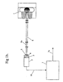
- One of the most effective situations is one in which there is a retroreflective background screen 2 and there is a source of infra-red illumination such as an array of infra-red LEDs 5 located near the optical axis of the camera.
- the viewer 1 is located in front of the screen 2.
- the camera 3 has a lens 4, the optical axis of which is directed towards the viewer 1.
- the infra-red LEDs 5 are located about the lenses 4 and emit light 8 in a direction towards the screen 2 and viewer 1.
- a camera 3 which may be a CCD camera 3.
- the aperture can simply be adjusted so that the exposed areas of the retroreflective screen 2 appear 100% white (saturation).
- the viewer 1 will then appear as a dark silhouette against the white background. It is then a reasonably simple task to locate the top and sides of the viewer's head through a simple thresholding process in software provided within a microprocessor 7 to determine the head co-ordinates 7a.
- FIG. 1(b) A variant on this arrangement which works well in a controlled environment which is free from incandescent lighting.
- This configuration consists of CCD camera 3 fitted with an infra-red pass filter 6 and an array of infra-red LEDs or other infra-red light source 5 located near the camera 3 and facing the viewer 1.
- the characteristic of interest is the high degree of reflectivity of the infra-red light from the viewer's face in comparison to that from the surroundings. It has been found in experiments that even a matt white background located at twice the viewer-camera distance afforded sufficient contrast for the subject's face to be easily discriminated from the background.
- the main difference between the images generated using this approach over that of the retroreflective screen is that in this case the image of the viewer's face will appear bright against a dark background.
- a second approach is to use acoustic range finding from several different locations on the display unit and utilising triangulation to find the position of the viewer's head.
- a system based upon four ultrasonic transducers, one on each corner of the 3D display, would operate as follows. One transducer is used to transmit a pulse, the other three transducers are set to receive the echoes from this pulse. The first pulse that is received (from the closest object) should be from the viewer's nose. By knowing the time delay between the sending of the pulse and when it was received by each sensor, the distance to the object (from each sensor) can be determined and a triangulation method used to locate this point in space.
- This procedure is then repeated by emitting a pulse from each sensor in turn and then maintaining a running average to improve the accuracy of the system. More complex algorithms and different numbers and configurations of transducers could be used to determine multiple points rather than only detecting the closest point.
- acoustic Holography techniques may be used to determine the position of the viewer's head. With sufficient resolution this technology could be used to determine the location of the viewers eyes.
- the shadow screen techniques appear to be one of the simplest and most cost effective of the many techniques available.
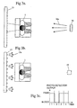
- the shadow screen can be configured in several ways as shown in Figures 3a and 3b.
- a single light source 16 (which may consist of an array of infra-red LEDs) would flood the viewer 1 with a source of coded or direct light 16a.
- An array of photodetectors 15 behind the viewer 1 would then decode the received light into either a "block” or "pass” situation.
- Coded light ie. modulated
- FIG. 3b An alternative configuration of the system is shown in Figure 3b.
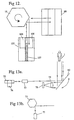
- the screen 17 is composed of light sources 17a and a single detector 18 is employed.
- This configuration is probably less expensive than that shown in Figure 3a because it requires only a single optical detector and amplifier section (which are generally more expensive than infra-red LEDs).
- the light sources could be modulated using either time multiplexing, frequency modulation or other appropriate modulation/coding techniques to allow the detector to discriminate one light source from another and thus to make possible a determination of which light source is being blocked by the viewer.
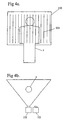
- FIG. 4 An alternative configuration of the system is shown in Figure 4.
- a series of vertical stripes of infra-red light 123 is projected at the viewer 1 and screen by an infra-red light source 121.
- An infra-red detector 122 receives reflections of the lines from the scene and by suitably time coding and modulating the stripes of infra-red light it is possible to determine the position of the viewers head.
- the system may be used without a reflective screen whereby the reflected infra-red stripes from the viewers face may be monitored with a video camera which may view the distortions in the vertical stripes and can determine depth information. These depth contours are then used to determine the position of the head.
- Eye tracking overcomes the problems of estimation encountered with head tracking by following the position of the viewer's eyes directly. This can be achieved by a number of means but of the different approaches the two most practical are:-
- Eye tracking systems based on retroreflectivity are ideally the most rugged and reliable as they are less affected by ambient light level changes and are immune to shadows and other similar optical distractions.
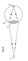
- the retroreflective eye tracking systems are based on primarily on the "cat's eye” principle i.e. as shown in Fig. 5 the characteristic of the eye 20 to reflect light back to its origin. This is due to the arrangement of the lens 22 and retina 21.
- the degree to which the retroreflectivity effect occurs is influenced by the intensity of the incident light, the area of the pupil and therefore the amount of diffuse reflection from the retina 21. This amount of reflection, and thus the effectiveness of the "cat's eye” effect is much greater in animals (such as cats and dogs) than in humans because of different eye physiology.
- it should be possible to achieve a functional system with a simple configuration such as shown in Figure 6 which can be designed to detect the brightest points of the image which should be the viewers eyes.
- the configuration shown in Figure 6 consists of a video camera 25 coupled to a pin hole lens 26. Surrounding the pin hole lens 26 is an array of infra-red LEDs 27. This configuration has been chosen so that the LED light sources 27 are as close to the optical axis of the camera lens 26 as possible in order to maximize the retroreflectivity effect from the viewer's eyes.
- the camera is positioned such that the light from the infra-red LEDs illuminates the viewers face and eyes.
- the video output from the camera 25 contains this image.
- the simplest differential analysis technique that can be employed is to capture one field with the infra-red LED light source switched on and then a second field with the light source switched off. These two images can then be subtracted in the computer and the difference further analysed.
- FIG. 7 A more workable configuration is shown in Figure 7 in which there are two arrays of LEDs 27 and 30 such that only one set is switched on at any time. Both arrays are circular and are concentric around the optical axis of the camera lens 26. Thus when array 27 is lit the camera 25 will receive a combination of direct reflection (from shiny surfaces) diffuse reflection (from matt surfaces) and retroreflection (from the viewer's eyes). When array 30 is lit the Camera will receive only direct reflection and matt reflection. Thus by subtracting the two images it is possible to extract the RETROREFLECTION from the other forms of reflection.
- Figure 8 consists of a pair of cameras 37, 38 in which a front surface mirror 48 splits the image from each lens in half.
- One of the cameras is fitted with a semi circle of infra-red LEDs 47 close to the optical axis of the camera such as shown for camera 37.
- This basic configuration operates as follows:-Camera 37 will receive retroreflection in addition to matt and direct reflection whereas camera 38 will receive only matt and direct reflection. Because Camera 38 is not illuminated along its optical axis it does not receive retroreflections. However unlike the previous example the two images have been captured concurrently and thus are not effected by viewer or camera movement. In this case the video information from both cameras is captured by a digital frame store and analysed by a computer utilising similar techniques as previously described.
- This method of adding polarisers to the light source and detector can be added to any of the above techniques.
- polarisers can be added to any of the above techniques.
- retroreflectivity techniques can be effective in determining the position of the eyes but these techniques may be problematic depending on the application.
- a major problem that has not been covered in the above discussion is the physiological influence of the eye on its retroreflectivity.
- any bright light incident on the eye will cause pupil contraction.
- the bright light may be from the bright images that are projected to each eye or from bright ambient lighting. As the light intensity increases the pupil contracts and the eye's retroreflectivity becomes significantly less detectable.
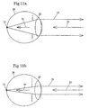
- FIG. 11(a) and (b) The mechanism by which pupil contraction affects the retroreflectivity index of the human eye is shown in Figure 11(a) and (b).
- a large portion of the incident light 33 is allowed into the eye 20.
- This light is then focused by the lens 22 to a point at the retina 21.
- the diffuse reflection from the retina 21 is then re-focused by the lens 22 into a parallel beam of light with intensity 32.
- pupil contraction as shown in Figure 11(b) much less of the incident light 33 is allowed into the eye to form the effective incident light 34 thus the intensity of the light returning to the lens from the focused spot is significantly reduced. Because of this the intensity of the returned light 32 is much lower than in the previous case ( ie. Fig.11(a) ) in addition to having a smaller return beam diameter.
- this system utilised a light source based around a scanned laser beam, and provided the laser beam used is smaller in diameter than the pupil diameter of the viewers eyes, then such a situation would exist.
- Figure 12 illustrates a laser transceiver module 105, a rotating mirror assembly 75 and a rotating or oscillating mirror assembly 80.
- the light beam can be caused to repeatedly scan across the viewers face in a manner similar to a 'Flying Spot Scanner' as used in television technology.
- Alternative techniques may be used to cause the light beam to scan across the viewers face such as a mirror or mirrors mounted upon a voice coil assembly or utilising micro mirror technology (as manufactured by Texas Instruments, USA).
- Laser assembly 105 consists of a modulated laser 107 and one or more optical detectors 106. The best performance can be achieved if the detectors are collimated through the use of lenses and are slightly displaced from the beam axis so that direct reflections from dust particles on the mirrors etc do riot cause the outgoing laser beam to be incorrectly detected as a return beam.
- Benefits can be derived through modulating the laser light source to eliminate the effects of ambient light.
- the serial ( point by point ) nature of the image detector probably PIN or avalanche diode
- the pupil diameter of the viewer may be quite small (perhaps 2mm) then it is considered better to modulate the beam on a pixel by pixel basis rather than using line based modulation as missing alternate scan lines may cause the pupil to be missed or ignored.
- a sine wave or triangular modulation of the laser beam be used as this will then allow conventional synchronous demodulation techniques to be employed effectively at the image decoding phase.
- a problem with the configuration shown in Figure 12 is that by virtue of the displacement between the optical axis of the laser 107 and detector modules 106 it will require that the primary beam deflector 75 be quite large. Alternate configurations for the system shown in Figure 13,14 and 15 overcome this problem by moving the detector optics 78,79 out of the optical path of the primary beam deflector thus allowing a significant reduction in the overall system dimensions.
- the single element detector has been replaced by a line based detector assembly 85, such as a linear CCD array, which would be read out after each scan of the laser beam.
- a conventional full field type scanning device such as a conventional CCD camera 110 through the use of a slightly different optical arrangement as shown in Figure 16. In this configuration the scanning system would scan in two axes utilising a single mirror arrangement 112 such as a two axis voice coil drive or other deflection system.
- FIG. 17 A practical implementation of this point divergence system is shown in Figure 17.
- the optical arrangement consists of a two axis prismatic scanning system followed by a projection lens.
- the return light from the subject is detected by a conventional CCD video camera 127 fitted with a pinhole lens 128.
- a conventional CCD video camera 127 fitted with a pinhole lens 128.
- One of the main advantages of this system over the previous systems is the simplicity of the detection system and the fact that the optical axis of the detector can be brought very close to the optical axis of the outgoing beam without any risk of cross talk between the outgoing beam and the detector return beam. This is possible due to the absence of mirrors and or other optical elements in the combined optical path.
- the system operates as follows. As in the previous systems a laser 120 (fitted with a polariser 121) is used to produce a collimated beam of light which in this case is incident upon a pair of rotating square or multisided prisms 124, 125.
- the prisms are orientated such that their rotational axis are at 90 degrees to each other. Due to the property of refraction, the prisms cause the laser beam to scan a rectangular area such that the emerging beam is always parallel to the beam incident to the prisms. This parallel scanned beam is then run through projection optics as shown. These optics translate the horizontal and vertical displacement into angular displacements (from the optical axis of the lens).
- the resulting scanned beam will converge to a focus point in front of the detection lens 128.
- the beam diameter will be in the order of only several millimetres and thus it becomes possible to place the lens 128 of the detection camera 127 very close to the optical axis of the projection system. This was not possible with any of the previous scanning systems because of the presence of two different points of beam convergence for the horizontal and vertical planes.
- This closeness to the optical axis of the laser beam greatly improves the ratio between retroreflection and normal diffuse reflection ( retroreflection index ) and thus improves the system effectiveness.
- An improvement to the laser techniques can be achieved if the light source is amplitude modulated with a sine wave of known frequency. Since only reflected light from the modulated light beam will be modulated with this known frequency, conventional coherent demodulation techniques can be used to detect the signals representing the retroreflections from the retina at the output of the light detector.
- any of the combinations of the above scanning and detection techniques may be used in the invention to determine the eye position depending on the application.
- the image analysis approach is the most sophisticated of all of the eye tracking systems. As with the retroreflective based system it uses a video camera fitted with an infra-red filter. The infra-red spectrum was chosen because of the reduced influence of skin pigmentation on the degree of reflectivity of light.
- the video camera is connected to a digital frame store and a microprocessor board.
- the microprocessor analyses the video information and identifies the position of firstly the viewer's head and then the viewer's eyes. It does this based on a general understanding of the nature and configuration of facial features and is independent of any specific viewer characteristic.
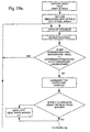
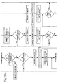
- the analysis takes place in two main stages as shown in Figure 18. Phase A -18(a), (b) and Phase B - 18(c).
- the first stage of analysis is to find the position of the viewer's head. This is important because it allows the search area for the viewer's eyes to be significantly reduced. This has dual advantages of firstly improving the frame rate of the analysis (i.e. speeding up the analysis) and secondly improving the accuracy of the analysis by masking out areas in which erroneous background information is present.
- the first step is to read in a field in low resolution (75 * 70). This field is then subtracted from a background array (of the same resolution). This difference information is then compared on a point by point basis against a threshold value of acceptable deviation. If the difference falls outside of this region then the point is considered "hot” i.e. the foreground in this region is different from the background. If the difference falls inside this region then the point is considered "cold".
- the "hot” points are then used to determine the top, left and right head markers, "cold” points are ignored, i.e. the highest "hot” point encountered is used to set the top-marker, the left-most "hot” point is used to set the left-most marker and the right-most "hot” point is used to set the right-most marker.
- a record is also kept of the total number of "hot” points encountered for each field analysed. This total number of points is compared with a threshold value. For a head position analysis to be considered valid, and the temporary head track markers to be subsequently copied to the working markers there must be at least as many "hot” points as this threshold value. If this situation is not met then the head-track search will be considered “cold", the eye-track search will not commence and the previous eye-positions will be maintained.
- the system has a reliable image of the background (i.e. without the viewer present) for correct processing to be possible.
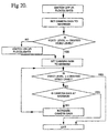
- This is handled by two different sections of the program. The first is the initialise section. This occurs once only during start-up and is outlined in Figure 20. During initialisation the gain of the camera is altered by the micro-processor board until the average video level is within a specified band. This is necessary to guarantee sufficient contrast within the image to allow correct analysis.
- This phase of the analysis determines the position of the viewer's eyes.
- the basic assumption made within this routine is that the viewer's eyes will be darker than the surrounding facial tissue. This is a safe assumption because there seems to be very little reflection of infra-red light from the iris and retina. Even though this situation is present there is of course no guarantee that other parts of the image are not equally dark, for example hair, nostrils, mouth etc.
- the one main distinguishing feature is that the eyes should be dark with a bright surround.
- the first step in the analysis is of course reading the video information from the frame store into the computer. As this information is being used to determine the eye position of the viewer it requires a higher resolution than that necessary for the head tracking section of the program. In this case a resolution of 150 * 140 (horizontal and vertical dots) was used although perhaps a slightly higher resolution on could be utilised to advantage.
- each analysis pixel represents an average of an 8 pixel cluster (4 * 2 cluster).
- This averaging helps to reduce the influence of noise in the video signal and improves the results slightly.
- this feature may be dropped in preference of reducing costs (by reducing the memory requirements of the frame-grabber component in the system).
- the video information read in from the frame grabber in high resolution is from the same video field as the information read in low resolution for the head-tracking phase of the analysis.
- the second step in the analysis is to determine the black-threshold level. This level is calculated from an analysis of the pixels found within the eye-track region (the region which is searched for eye-tracking). In the case of the existing software this level was calculated by searching all of the pixels to find the minimum and maximum levels. The black-level is then assigned as the mid point between these extremes, but other superior processes may be adopted in the future.
- the third step in the analysis is the detection of the dark regions. This is done firstly on a pixel by pixel basis by comparing the video level against the black-threshold level. If the foreground pixel is darker than this level it is considered active, if not, then it is considered inactive and ignored.
- the remaining pixels in the eye track region are analysed and classified as either "active” or “inactive” as discussed earlier.
- the "active" pixels are then tagged as active and placed in an activity array for the region searching routine to work with.
- a region search routine scans the activity array for active pixels. These pixels are then formed into groups using a region searching routine.
- the region search routine (shown simplified in Figure 22) returns a list of information about the objects (regions) that it has found. At the present this information consists of the left-most x coordinate, the right-most x coordinate, the top-most y coordinate, the bottom-most y coordinate and the area of the region in pixels.
- Objects are considered invalid and are ignored if any of the following conditions occur.
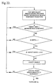
- the filtering section which is shown in Figure 23 is basically hierarchical with objects being ranked by their areas as the first criterion. They are stored into a list from largest to smallest then progressively removed from the list according to further geometric and inter-relational tests.
- the filtering is "adaptive" in nature in so much as it works on several dynamically variable levels of constraints or requirements.
- the filter starts off using the most stringent of the tests, then if no valid eye-pairs are found, reduces the constraints on the tests and re-tests the objects with this new set of requirements. If no valid eye-pairs are found then the test constraints are further reduced and the objects tested again. This pattern continues until a minimum constraint situation is met. If at this point no valid eye-pairs are found then the eye-lock flag is cleared and the previous eye positions are maintained.
- the first stage in this filtering process is to sort the objects from largest to smallest.
- the largest object in the list is then chosen as the "A" object and the "A" object removed from the current list.
- This current list is then copied into a secondary list.
- the first item of this secondary list i.e. the largest
- the object edges are checked to see if they are touching the eye-track window. This is an important test because it is quite common for the eye-track window to intersect the viewer's hairline thus creating a small isolated region which may from time to time get past the trim routine. it is however, not possible to simply ignore all objects that touch the eye-track window because it is quite common for a valid eye-region to do just this. This criterion has the lowest priority and if through its inclusion all object pairs are rejected then the test will re-start without the criterion. It should be noted that only the bottom and sides of the eye track window are tested in this manner. The top of the eye-track window does not need checking because the trim routine starts its checks along this edge and can thus almost guarantee that this top edge is clear after it has executed.
- the next check is one of aspect ratio of the object.
- aspect ratio has already been checked at an earlier stage of the analysis, the threshold aspect ratio in the earlier case was 2:1.
- the aspect ratio is checked against a lower (squarer) value of 3:2 (height to width). If the object has an aspect ratio greater than this value then it is rejected.
- this criterion could not simply be imposed at the earlier test of aspect ratio because it is often the case that the object is cut by the side of the eye-track window and thus appears to be of a higher aspect ratio than it actually is. Imposing this stricter aspect criterion is not a problem at this level because if it causes the rejection of valid eye-regions then the system will automatically drop this test criterion on the next pass through the filter loop.
- eye-lock is considered valid and the associated eye-lock flag is set.
- FIG 23 shows the filter program in straight-line code for clarity. It should be noted that the program may be implemented differently to improve compactness.
- the eye positions are calculated as a relative offset from the head-tracking markers, thus it is possible to lose eye-lock and yet still maintain eye-positions even with viewer-movement as the eye-positions will then be "estimated" from the last known offsets from the head track markers. If however, the head-lock is lost, the eye-lock is automatically lost because the eye track window cannot be determined.
- An auxiliary adaptive function in the eye-tracking section of the program allows the system to change the vertical offset between the top of the head-tracking marker and the top of the eye-tracking region thereby making the system more versatile in the handling of viewers with different hair lengths and styles.
- This routine called “track” uses the relative offset between the centre of the eye-track region and the vertical position of the last valid eye-pair to alter the degree of vertical offset. This adjustment, or “tracking”, can only occur while eye-lock is valid. If eye-lock is lost the eye-track window will slowly return to a centre position.
- stereoscopic systems require the viewer to be positioned a fixed distance away from the display apparatus in order to perceive a 3D image.
- the single camera and light detector systems described above may be modified to utilise two cameras or light detectors such that each receives a slightly different view of the scene. By comparing the difference in position of the viewer in the output of both cameras or light detectors the distance from the viewer to the display apparatus can be calculated and acted upon accordingly.
Applications Claiming Priority (4)
| Application Number | Priority Date | Filing Date | Title |
|---|---|---|---|
| AUPN038994 | 1994-12-13 | ||
| AUPN0038A AUPN003894A0 (en) | 1994-12-13 | 1994-12-13 | Head tracking system for stereoscopic display apparatus |
| AUPN0389/94 | 1994-12-13 | ||
| PCT/AU1995/000843 WO1996018925A1 (en) | 1994-12-13 | 1995-12-13 | Tracking system for stereoscopic display systems |
Publications (3)
| Publication Number | Publication Date |
|---|---|
| EP0797784A1 EP0797784A1 (en) | 1997-10-01 |
| EP0797784A4 EP0797784A4 (en) | 1999-03-24 |
| EP0797784B1 true EP0797784B1 (en) | 2003-07-30 |
Family
ID=3784545
Family Applications (1)
| Application Number | Title | Priority Date | Filing Date |
|---|---|---|---|
| EP95941539A Expired - Lifetime EP0797784B1 (en) | 1994-12-13 | 1995-12-13 | Tracking system for stereoscopic display systems |
Country Status (7)
| Country | Link |
|---|---|
| US (1) | US6163336A (zh) |
| EP (1) | EP0797784B1 (zh) |
| JP (1) | JPH10510686A (zh) |
| CN (1) | CN1175308A (zh) |
| AU (1) | AUPN003894A0 (zh) |
| CA (1) | CA2207793A1 (zh) |
| WO (1) | WO1996018925A1 (zh) |
Cited By (2)
| Publication number | Priority date | Publication date | Assignee | Title |
|---|---|---|---|---|
| DE102009001202B3 (de) * | 2009-02-26 | 2010-09-09 | Seereal Technologies S.A. | Kamerasystem mit Augenfinder-Modulen |
| CN108399613A (zh) * | 2017-12-20 | 2018-08-14 | 上海奕瑞光电子科技股份有限公司 | 一种平板探测器图像空场识别方法 |
Families Citing this family (130)
| Publication number | Priority date | Publication date | Assignee | Title |
|---|---|---|---|---|
| GB2296152B (en) * | 1994-12-13 | 1999-07-07 | Gec Marconi Avionics Holdings | An autostereoscopic display |
| AUPN003894A0 (en) * | 1994-12-13 | 1995-01-12 | Xenotech Research Pty Ltd | Head tracking system for stereoscopic display apparatus |
| GB2306826A (en) * | 1995-10-18 | 1997-05-07 | Sharp Kk | Display, method of calibrating an observer tracking display and observer tracking autostereoscopic 3D display |
| AUPO024696A0 (en) * | 1996-06-04 | 1996-06-27 | Xenotech Research Pty Ltd | Video display system |
| JP3751368B2 (ja) * | 1996-06-28 | 2006-03-01 | 沖電気工業株式会社 | 虹彩認識システムおよび虹彩認識装置 |
| US6108005A (en) * | 1996-08-30 | 2000-08-22 | Space Corporation | Method for producing a synthesized stereoscopic image |
| US6535241B1 (en) * | 1996-11-13 | 2003-03-18 | Fakespace Labs, Inc. | Multi-person stereo display system |
| JPH10268231A (ja) * | 1997-03-26 | 1998-10-09 | Philips Japan Ltd | 立体画像表示装置 |
| GB2324428A (en) * | 1997-04-17 | 1998-10-21 | Sharp Kk | Image tracking; observer tracking stereoscopic display |
| AUPP048097A0 (en) | 1997-11-21 | 1997-12-18 | Xenotech Research Pty Ltd | Eye tracking apparatus |
| AU1890699A (en) * | 1998-01-16 | 1999-08-02 | Nikon Corporation | Exposure method and lithography system, exposure apparatus and method of producing the apparatus, and method of producing device |
| US20010008561A1 (en) | 1999-08-10 | 2001-07-19 | Paul George V. | Real-time object tracking system |
| US7036094B1 (en) | 1998-08-10 | 2006-04-25 | Cybernet Systems Corporation | Behavior recognition system |
| US7121946B2 (en) * | 1998-08-10 | 2006-10-17 | Cybernet Systems Corporation | Real-time head tracking system for computer games and other applications |
| GB2341231A (en) * | 1998-09-05 | 2000-03-08 | Sharp Kk | Face detection in an image |
| US6757422B1 (en) * | 1998-11-12 | 2004-06-29 | Canon Kabushiki Kaisha | Viewpoint position detection apparatus and method, and stereoscopic image display system |
| EP1186148B1 (de) * | 1999-06-18 | 2002-12-11 | Swisscom Mobile AG | Übermittlung und darstellung von videodaten |
| US7050606B2 (en) * | 1999-08-10 | 2006-05-23 | Cybernet Systems Corporation | Tracking and gesture recognition system particularly suited to vehicular control applications |
| US7236622B2 (en) * | 1999-08-25 | 2007-06-26 | Eastman Kodak Company | Method for forming a depth image |
| US7928955B1 (en) * | 2000-03-13 | 2011-04-19 | Intel Corporation | Automatic brightness control for displays |
| US20080024598A1 (en) * | 2000-07-21 | 2008-01-31 | New York University | Autostereoscopic display |
| JP3659144B2 (ja) * | 2000-08-25 | 2005-06-15 | トヨタ自動車株式会社 | 入力画面の制御装置 |
| DE10044032A1 (de) * | 2000-09-06 | 2002-03-14 | Deutsche Telekom Ag | 3-D Sehen |
| US6543899B2 (en) * | 2000-12-05 | 2003-04-08 | Eastman Kodak Company | Auto-stereoscopic viewing system using mounted projection |
| US7111939B2 (en) * | 2001-01-22 | 2006-09-26 | Eastman Kodak Company | Image display system with body position compensation |
| US6752498B2 (en) | 2001-05-14 | 2004-06-22 | Eastman Kodak Company | Adaptive autostereoscopic display system |
| GB0128983D0 (en) * | 2001-12-04 | 2002-01-23 | Koninkl Philips Electronics Nv | Directional image dislay |
| DE10204430A1 (de) | 2002-02-04 | 2003-08-07 | Zeiss Carl | Stereo-Mikroskopieverfahren und Stereo-Mikroskopiesystem |
| EP1479046A4 (en) * | 2002-02-27 | 2007-01-31 | Geo Rae Co Ltd | METHOD AND SYSTEM FOR DISPLAYING A STEREOSCOPIC IMAGE |
| JP4147054B2 (ja) * | 2002-05-17 | 2008-09-10 | オリンパス株式会社 | 立体観察装置 |
| US7907150B2 (en) * | 2003-08-09 | 2011-03-15 | Doubleshot, Inc. | Method of fusion or merging imagery data for improved visual perception using monoscopic and stereographic fusion and retinal decay techniques |
| US20050207486A1 (en) * | 2004-03-18 | 2005-09-22 | Sony Corporation | Three dimensional acquisition and visualization system for personal electronic devices |
| US20050275915A1 (en) | 2004-06-01 | 2005-12-15 | Vesely Michael A | Multi-plane horizontal perspective display |
| US8300043B2 (en) * | 2004-06-24 | 2012-10-30 | Sony Ericsson Mobile Communications AG | Proximity assisted 3D rendering |
| US20060109202A1 (en) * | 2004-11-22 | 2006-05-25 | Alden Ray M | Multiple program and 3D display and 3D camera apparatus and process |
| FR2873457A1 (fr) * | 2004-07-23 | 2006-01-27 | Franck Andre Marie Guigan | Dispositif optique a reseau lenticulaire |
| FR2873459A1 (fr) * | 2004-07-23 | 2006-01-27 | Franck Andre Marie Guigan | Dispositif optique a reseau lenticulaire |
| KR100624431B1 (ko) | 2004-08-03 | 2006-09-19 | 삼성전자주식회사 | 입체영상 관찰을 위한 주시거리 조정 방법 및 그 장치 |
| US9030532B2 (en) * | 2004-08-19 | 2015-05-12 | Microsoft Technology Licensing, Llc | Stereoscopic image display |
| US20060152580A1 (en) * | 2005-01-07 | 2006-07-13 | Synthosys, Llc | Auto-stereoscopic volumetric imaging system and method |
| RU2322771C2 (ru) * | 2005-04-25 | 2008-04-20 | Святослав Иванович АРСЕНИЧ | Стереопроекционная система |
| US20060250391A1 (en) * | 2005-05-09 | 2006-11-09 | Vesely Michael A | Three dimensional horizontal perspective workstation |
| US8717423B2 (en) * | 2005-05-09 | 2014-05-06 | Zspace, Inc. | Modifying perspective of stereoscopic images based on changes in user viewpoint |
| US20070091037A1 (en) * | 2005-10-21 | 2007-04-26 | Yee-Chun Lee | Energy Efficient Compact Display For Mobile Device |
| DE112006003377B4 (de) * | 2005-12-22 | 2014-11-27 | Seereal Technologies S.A. | Verfahren zur multimodalen Darstellung von Bildinhalten auf einer Anzeigeeinrichtung für Videohologramme und multimodale Anzeigeeinrichtung |
| US7679041B2 (en) * | 2006-02-13 | 2010-03-16 | Ge Inspection Technologies, Lp | Electronic imaging device with photosensor arrays |
| US20080159551A1 (en) * | 2006-12-28 | 2008-07-03 | Texas Instruments Incorporated | System and Method for Acoustic Echo Removal (AER) |
| US8077964B2 (en) * | 2007-03-19 | 2011-12-13 | Sony Corporation | Two dimensional/three dimensional digital information acquisition and display device |
| KR101350475B1 (ko) * | 2007-04-12 | 2014-01-15 | 삼성전자주식회사 | 고효율 2차원/3차원 겸용 영상 표시장치 |
| WO2009050632A1 (en) * | 2007-10-16 | 2009-04-23 | Koninklijke Philips Electronics N.V. | Apparatus, systems and methods for production and integration of compact illumination schemes |
| US7938540B2 (en) * | 2008-07-21 | 2011-05-10 | Disney Enterprises, Inc. | Autostereoscopic projection system |
| US20100107184A1 (en) * | 2008-10-23 | 2010-04-29 | Peter Rae Shintani | TV with eye detection |
| CN102265204A (zh) * | 2008-10-27 | 2011-11-30 | 瑞尔D股份有限公司 | 头部追踪增强立体眼镜 |
| US8199186B2 (en) | 2009-03-05 | 2012-06-12 | Microsoft Corporation | Three-dimensional (3D) imaging based on motionparallax |
| US8284234B2 (en) * | 2009-03-20 | 2012-10-09 | Absolute Imaging LLC | Endoscopic imaging using reflection holographic optical element for autostereoscopic 3-D viewing |
| US8314832B2 (en) | 2009-04-01 | 2012-11-20 | Microsoft Corporation | Systems and methods for generating stereoscopic images |
| US11450113B1 (en) | 2009-06-04 | 2022-09-20 | Masoud Vaziri | Method and apparatus for a wearable computer |
| US8872910B1 (en) * | 2009-06-04 | 2014-10-28 | Masoud Vaziri | Method and apparatus for a compact and high resolution eye-view recorder |
| US10064552B1 (en) | 2009-06-04 | 2018-09-04 | Masoud Vaziri | Method and apparatus for a compact and high resolution mind-view communicator |
| US11367164B1 (en) | 2009-06-04 | 2022-06-21 | Masoud Vaziri | Method and apparatus for super resolution imaging and eye tracking devices |
| US7948515B1 (en) * | 2009-06-05 | 2011-05-24 | Hines Stephen P | Mini 3-D camera rig |
| US8867820B2 (en) | 2009-10-07 | 2014-10-21 | Microsoft Corporation | Systems and methods for removing a background of an image |
| US7961910B2 (en) * | 2009-10-07 | 2011-06-14 | Microsoft Corporation | Systems and methods for tracking a model |
| US8564534B2 (en) | 2009-10-07 | 2013-10-22 | Microsoft Corporation | Human tracking system |
| US8963829B2 (en) | 2009-10-07 | 2015-02-24 | Microsoft Corporation | Methods and systems for determining and tracking extremities of a target |
| US9088791B2 (en) * | 2009-11-17 | 2015-07-21 | Eidgenossische Technische Hochschule Zurich | Transparent autostereoscopic image display apparatus and method |
| IT1397294B1 (it) * | 2010-01-07 | 2013-01-04 | 3Dswitch S R L | Dispositivo e metodo per il riconoscimento di occhiali per visione stereoscopica, e relativometodo di controllo della visualizzazione di un flusso video stereoscopico. |
| US8717360B2 (en) | 2010-01-29 | 2014-05-06 | Zspace, Inc. | Presenting a view within a three dimensional scene |
| JP5499854B2 (ja) * | 2010-04-08 | 2014-05-21 | ソニー株式会社 | 頭部装着型ディスプレイにおける光学的位置調整方法 |
| RU2564049C2 (ru) * | 2010-05-21 | 2015-09-27 | Конинклейке Филипс Электроникс Н.В. | Многовидовое устройство формирования изображения |
| US8878773B1 (en) * | 2010-05-24 | 2014-11-04 | Amazon Technologies, Inc. | Determining relative motion as input |
| JP4875762B2 (ja) * | 2010-05-26 | 2012-02-15 | シャープ株式会社 | 画像処理装置、画像表示装置および画像撮像装置 |
| KR101699922B1 (ko) | 2010-08-12 | 2017-01-25 | 삼성전자주식회사 | 하이브리드 사용자 추적 센서를 이용한 디스플레이 시스템 및 방법 |
| CN102004256B (zh) * | 2010-09-09 | 2012-07-04 | 北京航空航天大学 | 基于空间谱全息存储的激光干涉测距系统 |
| CN102045577B (zh) * | 2010-09-27 | 2013-03-27 | 昆山龙腾光电有限公司 | 用于三维立体显示的观察者跟踪系统及三维立体显示系统 |
| US8830329B2 (en) * | 2010-10-07 | 2014-09-09 | Sony Computer Entertainment Inc. | 3-D glasses with camera based head tracking |
| EP2486441B1 (en) * | 2010-10-07 | 2018-02-21 | Sony Interactive Entertainment Inc. | 3-d glasses with camera based head tracking |
| GB2484919A (en) * | 2010-10-25 | 2012-05-02 | Cambridge Silicon Radio | Directional display device arranged to display visual content toward a viewer |
| US20120098931A1 (en) * | 2010-10-26 | 2012-04-26 | Sony Corporation | 3d motion picture adaption system |
| US9354718B2 (en) * | 2010-12-22 | 2016-05-31 | Zspace, Inc. | Tightly coupled interactive stereo display |
| WO2012097503A1 (zh) * | 2011-01-18 | 2012-07-26 | 青岛海信信芯科技有限公司 | 一种立体显示的控制方法及装置 |
| US8786529B1 (en) | 2011-05-18 | 2014-07-22 | Zspace, Inc. | Liquid crystal variable drive voltage |
| US8885882B1 (en) | 2011-07-14 | 2014-11-11 | The Research Foundation For The State University Of New York | Real time eye tracking for human computer interaction |
| US9102269B2 (en) | 2011-08-09 | 2015-08-11 | Continental Automotive Systems, Inc. | Field of view matching video display system |
| US20130093752A1 (en) * | 2011-10-13 | 2013-04-18 | Sharp Laboratories Of America, Inc. | Viewer reactive auto stereoscopic display |
| US20130100243A1 (en) * | 2011-10-20 | 2013-04-25 | Broadcom Corporation | Secure Stereoscopic Display |
| KR101920646B1 (ko) * | 2011-12-15 | 2018-11-22 | 한국전자통신연구원 | 시각인식 기반의 프로그래시브 비디오 스트리밍 장치 및 방법 |
| US20130271575A1 (en) * | 2012-04-11 | 2013-10-17 | Zspace, Inc. | Dynamically Controlling an Imaging Microscopy System |
| CN103581654A (zh) * | 2012-07-30 | 2014-02-12 | 联想(北京)有限公司 | 一种信息处理方法 |
| US9584797B2 (en) | 2012-10-31 | 2017-02-28 | Elwha Llc | Systems and methods to confirm that an autostereoscopic display is accurately aimed |
| KR20140063272A (ko) * | 2012-11-16 | 2014-05-27 | 엘지전자 주식회사 | 영상표시장치, 및 그 동작방법 |
| US9265458B2 (en) | 2012-12-04 | 2016-02-23 | Sync-Think, Inc. | Application of smooth pursuit cognitive testing paradigms to clinical drug development |
| TWI516093B (zh) * | 2012-12-22 | 2016-01-01 | 財團法人工業技術研究院 | 影像互動系統、手指位置的偵測方法、立體顯示系統以及立體顯示器的控制方法 |
| JP2014127999A (ja) * | 2012-12-27 | 2014-07-07 | Toshiba Corp | 顔検出装置 |
| US11004337B2 (en) | 2012-12-28 | 2021-05-11 | Balu Subramanya | Advanced parking management system |
| US20140210646A1 (en) * | 2012-12-28 | 2014-07-31 | Balu Subramanya | Advanced parking and intersection management system |
| US9380976B2 (en) | 2013-03-11 | 2016-07-05 | Sync-Think, Inc. | Optical neuroinformatics |
| US9094576B1 (en) | 2013-03-12 | 2015-07-28 | Amazon Technologies, Inc. | Rendered audiovisual communication |
| CN103248905A (zh) * | 2013-03-22 | 2013-08-14 | 深圳市云立方信息科技有限公司 | 一种模仿全息3d场景的显示装置和视觉显示方法 |
| US10228561B2 (en) | 2013-06-25 | 2019-03-12 | Microsoft Technology Licensing, Llc | Eye-tracking system using a freeform prism and gaze-detection light |
| US9625723B2 (en) | 2013-06-25 | 2017-04-18 | Microsoft Technology Licensing, Llc | Eye-tracking system using a freeform prism |
| CN103402106B (zh) * | 2013-07-25 | 2016-01-06 | 青岛海信电器股份有限公司 | 三维图像显示方法及装置 |
| US9736467B2 (en) * | 2013-08-05 | 2017-08-15 | Samsung Display Co., Ltd. | Apparatus and method for adjusting stereoscopic images in response to head roll |
| TWI508526B (zh) * | 2013-10-01 | 2015-11-11 | Wistron Corp | 產生視角平移影像之方法及其可攜式電子設備 |
| US20150169046A1 (en) * | 2013-12-13 | 2015-06-18 | Honeywell International Inc. | Line scan camera eye tracking system and method |
| US9720506B2 (en) * | 2014-01-14 | 2017-08-01 | Microsoft Technology Licensing, Llc | 3D silhouette sensing system |
| CN103984068B (zh) * | 2014-06-03 | 2016-07-27 | 苏州洛合镭信光电科技有限公司 | Qfn封装的宽带高速传输的并行光收发组件 |
| TWI556624B (zh) * | 2014-07-18 | 2016-11-01 | 友達光電股份有限公司 | 影像顯示方法以及影像顯示裝置 |
| CN104503092B (zh) * | 2014-11-28 | 2018-04-10 | 深圳市魔眼科技有限公司 | 不同角度和距离自适应的三维显示方法及设备 |
| CN104460019B (zh) * | 2014-12-11 | 2017-04-12 | 合肥鑫晟光电科技有限公司 | 三维显示设备以及三维显示方法 |
| US9754506B2 (en) | 2015-03-31 | 2017-09-05 | Cae Inc. | Interactive computer program with virtualized participant |
| US20160292919A1 (en) | 2015-03-31 | 2016-10-06 | Cae Inc. | Modular Infrastructure For An Interactive Computer Program |
| CA2980384C (en) * | 2015-03-31 | 2022-04-05 | Cae Inc. | Multifactor eye position identification in a display system |
| US20170008621A1 (en) * | 2015-07-08 | 2017-01-12 | Honeywell International Inc. | Accurate object detection in free space using controlled light source techniques |
| US10359215B2 (en) * | 2015-08-06 | 2019-07-23 | Edisun Microgrids, Inc. | Heliostat array intensity and polarization tracking |
| CN106325033A (zh) * | 2016-08-22 | 2017-01-11 | 京东方科技集团股份有限公司 | 全息显示装置 |
| CN106292240A (zh) * | 2016-09-05 | 2017-01-04 | 京东方科技集团股份有限公司 | 全息显示装置及其显示方法 |
| CN106599656A (zh) * | 2016-11-28 | 2017-04-26 | 深圳超多维科技有限公司 | 显示方法、装置及电子设备 |
| JP6454368B2 (ja) * | 2017-03-15 | 2019-01-16 | 株式会社Subaru | 車両の表示システム及び車両の表示システムの制御方法 |
| EP3619704A4 (en) * | 2017-05-01 | 2020-11-11 | Pure Depth Inc. | SACCADED SEQUENTIAL FIELD FRAGMENTATION REDUCTION BASED ON HEAD TRACKING |
| US20200371378A1 (en) * | 2017-08-23 | 2020-11-26 | Pcms Holdings, Inc. | Light field image engine method and apparatus for generating projected 3d light fields |
| US11624934B2 (en) | 2017-11-02 | 2023-04-11 | Interdigital Madison Patent Holdings, Sas | Method and system for aperture expansion in light field displays |
| JP2022540350A (ja) | 2019-06-28 | 2022-09-15 | ピーシーエムエス ホールディングス インコーポレイテッド | 調整可能な液晶(lc)ディフューザに基づいたライトフィールド(lf)ディスプレイのための光学的方法およびシステム |
| EP3990966A1 (en) * | 2019-07-01 | 2022-05-04 | PCMS Holdings, Inc. | Method and system for continuous calibration of a 3d display based on beam steering |
| JP2023508342A (ja) * | 2019-12-19 | 2023-03-02 | エーワイイースリーディー・インコーポレイテッド | 立体視画像を見せるための方法およびディスプレイシステム |
| CN112414310A (zh) * | 2020-11-13 | 2021-02-26 | 浙江汉振智能技术有限公司 | 三维激光跟踪测距装置及方法 |
| CN113013781B (zh) * | 2021-02-05 | 2022-04-01 | 安阳一都网络科技有限公司 | 基于图像处理的激光发射及动态校准装置、方法、设备和介质 |
| CN115220240B (zh) * | 2021-04-19 | 2023-11-21 | 幻景启动股份有限公司 | 适应眼睛位置的立体影像数据的产生方法与显示系统 |
| CN113325572B (zh) * | 2021-05-27 | 2023-05-23 | 京东方科技集团股份有限公司 | 可穿戴显示设备及注视点的位置的确定方法 |
| US11800244B1 (en) | 2022-08-13 | 2023-10-24 | Mojtaba Vaziri | Method and apparatus for an imaging device |
Family Cites Families (30)
| Publication number | Priority date | Publication date | Assignee | Title |
|---|---|---|---|---|
| US2727429A (en) * | 1953-11-30 | 1955-12-20 | Will F Jenkins | Apparatus for the production of composite photographic effects |
| GB1563188A (en) * | 1975-10-17 | 1980-03-19 | Perisic Z | Optical method and apparatus for carrying out the method |
| GB2041562B (en) * | 1978-12-21 | 1983-09-01 | Redifon Simulation Ltd | Visual display apparatus |
| GB2041563B (en) * | 1979-01-11 | 1983-08-17 | Redifon Simulation Ltd | Visual display apparatus |
| US4649425A (en) * | 1983-07-25 | 1987-03-10 | Pund Marvin L | Stereoscopic display |
| DE3407686C1 (de) * | 1984-03-02 | 1985-07-11 | Drägerwerk AG, 2400 Lübeck | Messgeraet fuer Gase mittels eines Indikatorbandes |
| JPS6318213A (ja) * | 1986-07-11 | 1988-01-26 | Hamamatsu Photonics Kk | ステレオ画像を用いた距離計測装置 |
| JPS63121387A (ja) * | 1986-11-10 | 1988-05-25 | A T R Tsushin Syst Kenkyusho:Kk | 立体画像表示装置 |
| GB8701288D0 (en) * | 1987-01-21 | 1987-02-25 | Waldern J D | Perception of computer-generated imagery |
| US4987487A (en) * | 1988-08-12 | 1991-01-22 | Nippon Telegraph And Telephone Corporation | Method of stereoscopic images display which compensates electronically for viewer head movement |
| US5086354A (en) * | 1989-02-27 | 1992-02-04 | Bass Robert E | Three dimensional optical viewing system |
| US5223925A (en) * | 1990-10-28 | 1993-06-29 | Tomohiko Hattori | Autostereoscopic system |
| US5024521A (en) * | 1990-11-19 | 1991-06-18 | Larry Zuchowski | Autostereoscopic presentation system |
| GB2259213A (en) * | 1991-08-29 | 1993-03-03 | British Aerospace | Variable resolution view-tracking display |
| US5189452A (en) * | 1991-12-09 | 1993-02-23 | General Electric Company | Real image projection system |
| US5329323A (en) * | 1992-03-25 | 1994-07-12 | Kevin Biles | Apparatus and method for producing 3-dimensional images |
| US5311220A (en) * | 1992-06-10 | 1994-05-10 | Dimension Technologies, Inc. | Autostereoscopic display |
| IL102370A (en) * | 1992-06-30 | 1995-03-30 | Yissum Res Dev Co | Process for modifying particulate solids and particulate solids prepared thereby |
| WO1994006249A1 (en) * | 1992-09-09 | 1994-03-17 | Eichenlaub Jesse B | Stroboscopic illumination system for video displays |
| US5349379A (en) * | 1992-09-09 | 1994-09-20 | Dimension Technologies Inc. | Autostereoscopic display illumination system allowing viewing zones to follow the observer's head |
| US5320538A (en) * | 1992-09-23 | 1994-06-14 | Hughes Training, Inc. | Interactive aircraft training system and method |
| JP3311832B2 (ja) * | 1992-10-14 | 2002-08-05 | テルモ株式会社 | 立体画像表示装置 |
| US5394202A (en) * | 1993-01-14 | 1995-02-28 | Sun Microsystems, Inc. | Method and apparatus for generating high resolution 3D images in a head tracked stereo display system |
| US5712732A (en) * | 1993-03-03 | 1998-01-27 | Street; Graham Stewart Brandon | Autostereoscopic image display adjustable for observer location and distance |
| DE4312918A1 (de) * | 1993-04-14 | 1994-10-20 | Hertz Inst Heinrich | Wiedergabeeinrichtung |
| JPH08511631A (ja) * | 1993-05-04 | 1996-12-03 | ゼノテック リサーチ プロプライエタリー リミテッド | 立体映像表示ユニット |
| JPH08163603A (ja) * | 1994-08-05 | 1996-06-21 | Tomohiko Hattori | 立体映像表示装置 |
| US5483308A (en) * | 1994-08-30 | 1996-01-09 | Youngker; Ray | Apparatus and method for displaying floor, ceiling, and wall coverings |
| AUPN003894A0 (en) * | 1994-12-13 | 1995-01-12 | Xenotech Research Pty Ltd | Head tracking system for stereoscopic display apparatus |
| US5956180A (en) * | 1996-12-31 | 1999-09-21 | Bass; Robert | Optical viewing system for asynchronous overlaid images |
-
1994
- 1994-12-13 AU AUPN0038A patent/AUPN003894A0/en not_active Abandoned
-
1995
- 1995-12-13 CN CN95197588A patent/CN1175308A/zh active Pending
- 1995-12-13 EP EP95941539A patent/EP0797784B1/en not_active Expired - Lifetime
- 1995-12-13 WO PCT/AU1995/000843 patent/WO1996018925A1/en active IP Right Grant
- 1995-12-13 CA CA002207793A patent/CA2207793A1/en not_active Abandoned
- 1995-12-13 US US08/849,777 patent/US6163336A/en not_active Expired - Fee Related
- 1995-12-13 JP JP8517950A patent/JPH10510686A/ja not_active Ceased
Cited By (2)
| Publication number | Priority date | Publication date | Assignee | Title |
|---|---|---|---|---|
| DE102009001202B3 (de) * | 2009-02-26 | 2010-09-09 | Seereal Technologies S.A. | Kamerasystem mit Augenfinder-Modulen |
| CN108399613A (zh) * | 2017-12-20 | 2018-08-14 | 上海奕瑞光电子科技股份有限公司 | 一种平板探测器图像空场识别方法 |
Also Published As
| Publication number | Publication date |
|---|---|
| AUPN003894A0 (en) | 1995-01-12 |
| CN1175308A (zh) | 1998-03-04 |
| EP0797784A4 (en) | 1999-03-24 |
| WO1996018925A1 (en) | 1996-06-20 |
| JPH10510686A (ja) | 1998-10-13 |
| US6163336A (en) | 2000-12-19 |
| CA2207793A1 (en) | 1996-06-20 |
| EP0797784A1 (en) | 1997-10-01 |
Similar Documents
| Publication | Publication Date | Title |
|---|---|---|
| EP0797784B1 (en) | Tracking system for stereoscopic display systems | |
| US6856341B2 (en) | Viewpoint detecting apparatus, viewpoint detecting method, and three-dimensional image display system | |
| US20030012425A1 (en) | Viewpoint position detection apparatus and method, and stereoscopic image display system | |
| CN100429559C (zh) | 虚像显示设备 | |
| US9106902B2 (en) | Depth information detection apparatus and apparatus for obtaining 3-dimensional content using the same | |
| US9477305B2 (en) | Stereoscopic image display apparatus and computer-readable recording medium storing program thereon | |
| CN110914786A (zh) | 用于在外部场景与虚拟图像之间配准的方法和系统 | |
| US11567566B2 (en) | Devices and methods for monitoring gaze | |
| US9002053B2 (en) | Iris recognition systems | |
| US20100259598A1 (en) | Apparatus for detecting three-dimensional distance | |
| US10310369B2 (en) | Stereoscopic reproduction system using transparency | |
| JP2662252B2 (ja) | 立体像表示装置 | |
| AU713400B2 (en) | Tracking system for stereoscopic display systems | |
| AU5010699A (en) | Tracking system for stereoscopic display systems | |
| JP2006267767A (ja) | 画像表示装置 | |
| JP2001056212A (ja) | 位置検出装置およびこれを用いた頭部位置追従型立体表示装置 | |
| JP2011139339A (ja) | 立体画像表示装置 | |
| CN213091888U (zh) | 深度测量系统及电子设备 | |
| CN105049833B (zh) | 一种采用对称可调式背光结构的立体视检查方法和装置 | |
| JP2001095014A (ja) | 位置検出装置およびこれを用いた頭部位置追従型立体表示装置 | |
| US10928894B2 (en) | Eye tracking | |
| JP3578808B2 (ja) | 立体表示装置 | |
| JP2013062560A (ja) | 画像処理装置、画像処理方法、及びプログラム | |
| US20230043439A1 (en) | 3d mapping in 2d scanning display | |
| JP3361205B2 (ja) | 立体画像表示装置 |
Legal Events
| Date | Code | Title | Description |
|---|---|---|---|
| PUAI | Public reference made under article 153(3) epc to a published international application that has entered the european phase |
Free format text: ORIGINAL CODE: 0009012 |
|
| 17P | Request for examination filed |
Effective date: 19970704 |
|
| AK | Designated contracting states |
Kind code of ref document: A1 Designated state(s): DE FR GB IT SE |
|
| A4 | Supplementary search report drawn up and despatched |
Effective date: 19990205 |
|
| AK | Designated contracting states |
Kind code of ref document: A4 Designated state(s): DE FR GB IT SE |
|
| RAP1 | Party data changed (applicant data changed or rights of an application transferred) |
Owner name: DYNAMIC DIGITAL DEPTH RESEARCH PTY. LTD. |
|
| RAP1 | Party data changed (applicant data changed or rights of an application transferred) |
Owner name: DYNAMIC DIGITAL DEPTH RESEARCH PTY. LTD. |
|
| 17Q | First examination report despatched |
Effective date: 20020118 |
|
| GRAH | Despatch of communication of intention to grant a patent |
Free format text: ORIGINAL CODE: EPIDOS IGRA |
|
| GRAH | Despatch of communication of intention to grant a patent |
Free format text: ORIGINAL CODE: EPIDOS IGRA |
|
| GRAA | (expected) grant |
Free format text: ORIGINAL CODE: 0009210 |
|
| AK | Designated contracting states |
Designated state(s): DE FR GB IT SE |
|
| PG25 | Lapsed in a contracting state [announced via postgrant information from national office to epo] |
Ref country code: IT Free format text: LAPSE BECAUSE OF FAILURE TO SUBMIT A TRANSLATION OF THE DESCRIPTION OR TO PAY THE FEE WITHIN THE PRE;WARNING: LAPSES OF ITALIAN PATENTS WITH EFFECTIVE DATE BEFORE 2007 MAY HAVE OCCURRED AT ANY TIME BEFORE 2007. THE CORRECT EFFECTIVE DATE MAY BE DIFFERENT FROM THE ONE RECORDED.SCRIBED TIME-LIMIT Effective date: 20030730 Ref country code: FR Free format text: LAPSE BECAUSE OF NON-PAYMENT OF DUE FEES Effective date: 20030730 |
|
| REG | Reference to a national code |
Ref country code: GB Ref legal event code: FG4D |
|
| REF | Corresponds to: |
Ref document number: 69531411 Country of ref document: DE Date of ref document: 20030904 Kind code of ref document: P |
|
| PG25 | Lapsed in a contracting state [announced via postgrant information from national office to epo] |
Ref country code: SE Free format text: LAPSE BECAUSE OF FAILURE TO SUBMIT A TRANSLATION OF THE DESCRIPTION OR TO PAY THE FEE WITHIN THE PRESCRIBED TIME-LIMIT Effective date: 20031030 |
|
| PG25 | Lapsed in a contracting state [announced via postgrant information from national office to epo] |
Ref country code: DE Free format text: LAPSE BECAUSE OF FAILURE TO SUBMIT A TRANSLATION OF THE DESCRIPTION OR TO PAY THE FEE WITHIN THE PRESCRIBED TIME-LIMIT Effective date: 20031031 |
|
| PG25 | Lapsed in a contracting state [announced via postgrant information from national office to epo] |
Ref country code: GB Free format text: LAPSE BECAUSE OF NON-PAYMENT OF DUE FEES Effective date: 20031213 |
|
| PLBE | No opposition filed within time limit |
Free format text: ORIGINAL CODE: 0009261 |
|
| STAA | Information on the status of an ep patent application or granted ep patent |
Free format text: STATUS: NO OPPOSITION FILED WITHIN TIME LIMIT |
|
| 26N | No opposition filed |
Effective date: 20040504 |
|
| GBPC | Gb: european patent ceased through non-payment of renewal fee |
Effective date: 20031213 |
|
| EN | Fr: translation not filed |