EP0797752B1 - Kälte-verfahren und -vorrichtung - Google Patents
Kälte-verfahren und -vorrichtung Download PDFInfo
- Publication number
- EP0797752B1 EP0797752B1 EP95934182A EP95934182A EP0797752B1 EP 0797752 B1 EP0797752 B1 EP 0797752B1 EP 95934182 A EP95934182 A EP 95934182A EP 95934182 A EP95934182 A EP 95934182A EP 0797752 B1 EP0797752 B1 EP 0797752B1
- Authority
- EP
- European Patent Office
- Prior art keywords
- gas
- container
- adsorbent material
- pressure
- adsorbable
- Prior art date
- Legal status (The legal status is an assumption and is not a legal conclusion. Google has not performed a legal analysis and makes no representation as to the accuracy of the status listed.)
- Expired - Lifetime
Links
Images
Classifications
-
- F—MECHANICAL ENGINEERING; LIGHTING; HEATING; WEAPONS; BLASTING
- F25—REFRIGERATION OR COOLING; COMBINED HEATING AND REFRIGERATION SYSTEMS; HEAT PUMP SYSTEMS; MANUFACTURE OR STORAGE OF ICE; LIQUEFACTION SOLIDIFICATION OF GASES
- F25B—REFRIGERATION MACHINES, PLANTS OR SYSTEMS; COMBINED HEATING AND REFRIGERATION SYSTEMS; HEAT PUMP SYSTEMS
- F25B35/00—Boiler-absorbers, i.e. boilers usable for absorption or adsorption
- F25B35/04—Boiler-absorbers, i.e. boilers usable for absorption or adsorption using a solid as sorbent
-
- F—MECHANICAL ENGINEERING; LIGHTING; HEATING; WEAPONS; BLASTING
- F25—REFRIGERATION OR COOLING; COMBINED HEATING AND REFRIGERATION SYSTEMS; HEAT PUMP SYSTEMS; MANUFACTURE OR STORAGE OF ICE; LIQUEFACTION SOLIDIFICATION OF GASES
- F25B—REFRIGERATION MACHINES, PLANTS OR SYSTEMS; COMBINED HEATING AND REFRIGERATION SYSTEMS; HEAT PUMP SYSTEMS
- F25B17/00—Sorption machines, plants or systems, operating intermittently, e.g. absorption or adsorption type
- F25B17/08—Sorption machines, plants or systems, operating intermittently, e.g. absorption or adsorption type the absorbent or adsorbent being a solid, e.g. salt
-
- F—MECHANICAL ENGINEERING; LIGHTING; HEATING; WEAPONS; BLASTING
- F25—REFRIGERATION OR COOLING; COMBINED HEATING AND REFRIGERATION SYSTEMS; HEAT PUMP SYSTEMS; MANUFACTURE OR STORAGE OF ICE; LIQUEFACTION SOLIDIFICATION OF GASES
- F25B—REFRIGERATION MACHINES, PLANTS OR SYSTEMS; COMBINED HEATING AND REFRIGERATION SYSTEMS; HEAT PUMP SYSTEMS
- F25B9/00—Compression machines, plants or systems, in which the refrigerant is air or other gas of low boiling point
- F25B9/002—Compression machines, plants or systems, in which the refrigerant is air or other gas of low boiling point characterised by the refrigerant
- F25B9/008—Compression machines, plants or systems, in which the refrigerant is air or other gas of low boiling point characterised by the refrigerant the refrigerant being carbon dioxide
-
- F—MECHANICAL ENGINEERING; LIGHTING; HEATING; WEAPONS; BLASTING
- F25—REFRIGERATION OR COOLING; COMBINED HEATING AND REFRIGERATION SYSTEMS; HEAT PUMP SYSTEMS; MANUFACTURE OR STORAGE OF ICE; LIQUEFACTION SOLIDIFICATION OF GASES
- F25D—REFRIGERATORS; COLD ROOMS; ICE-BOXES; COOLING OR FREEZING APPARATUS NOT OTHERWISE PROVIDED FOR
- F25D9/00—Devices not associated with refrigerating machinery and not covered by groups F25D1/00 - F25D7/00; Combinations of devices covered by two or more of the groups F25D1/00 - F25D7/00
-
- F—MECHANICAL ENGINEERING; LIGHTING; HEATING; WEAPONS; BLASTING
- F25—REFRIGERATION OR COOLING; COMBINED HEATING AND REFRIGERATION SYSTEMS; HEAT PUMP SYSTEMS; MANUFACTURE OR STORAGE OF ICE; LIQUEFACTION SOLIDIFICATION OF GASES
- F25D—REFRIGERATORS; COLD ROOMS; ICE-BOXES; COOLING OR FREEZING APPARATUS NOT OTHERWISE PROVIDED FOR
- F25D2400/00—General features of, or devices for refrigerators, cold rooms, ice-boxes, or for cooling or freezing apparatus not covered by any other subclass
- F25D2400/26—Refrigerating devices for cooling wearing apparel, e.g. garments, hats, shoes or gloves
-
- Y—GENERAL TAGGING OF NEW TECHNOLOGICAL DEVELOPMENTS; GENERAL TAGGING OF CROSS-SECTIONAL TECHNOLOGIES SPANNING OVER SEVERAL SECTIONS OF THE IPC; TECHNICAL SUBJECTS COVERED BY FORMER USPC CROSS-REFERENCE ART COLLECTIONS [XRACs] AND DIGESTS
- Y02—TECHNOLOGIES OR APPLICATIONS FOR MITIGATION OR ADAPTATION AGAINST CLIMATE CHANGE
- Y02B—CLIMATE CHANGE MITIGATION TECHNOLOGIES RELATED TO BUILDINGS, e.g. HOUSING, HOUSE APPLIANCES OR RELATED END-USER APPLICATIONS
- Y02B30/00—Energy efficient heating, ventilation or air conditioning [HVAC]
- Y02B30/62—Absorption based systems
Definitions
- the invention relates to a method and a device. refrigerants.
- EP-A-0 523 849 describes a device, based on this principle, consisting of a cylinder containing an adsorbent material and a compressible gas (such as CO 2 ), and a piston actuated by a compressor to compress the gas so to have it adsorbed by the adsorbent material.
- a piston When the piston is retracted, the gas desorbs and produces cold.
- Means are provided for cooling the hot zone and conveying the frigories from the cold zone to an enclosure to be refrigerated.
- This device which requires a compressor to operate the piston, suffers from being heavy and bulky. he clearly not a refrigerant designed to be light and portable.
- Document US-A-1,729,083 describes a process for producing cold by evaporation and adsorption of vapors by an adsorbent material contained in a tank.
- the invention relates to a new production process. cold by desorption of a gas previously adsorbed in an adsorbent material contained in a tank, characterized in that the gas is desorbed under controlled pressure higher than the pressure atmospheric and in that the desorbed gas is discharged to the atmosphere or caught in a trap.
- the desorbed gas is neither reused nor transferred to another enclosure to be recycled later, and this particularity authorizes the production of refrigeration devices which are simple, light and portable.
- controlled pressure we mean a pressure constant or substantially constant or even a pressure variable whose variation is regulated according to a given parameter, in particular of the device temperature implementing said method or article or enclosure cooled by the cold generated by means of a device implementing the present process.
- Desorption of gas is carried out under pressure controlled above atmospheric pressure so to prevent air from entering the tank containing the adsorbent material.
- the present invention also relates to a device refrigerant which is light, portable and simple realization.
- the invention relates to a refrigerant device comprising a reservoir holding the pressure filled with an adsorbent material in which the cold is produced by desorption of a gas previously adsorbed in said adsorbent material, characterized in that that it includes, in addition, an adjustable tare valve whose the passage communicates, on the one hand, with the interior of the tank and, on the other hand, directly with the outside, and means to put said tank temporarily in communication with a pressurized source of gas adsorbable by said adsorbent material.
- said means consist of a quick coupling of the self-sealing type in two parts, one of which is attached to the tank and the other part is attached to the valve, so that the tank can be disconnected from the valve and connected to said pressure source to be filled with gas adsorbable.
- a percussion type refill i.e. type comprising a needle, the channel of which is connected by via a valve or similar to the chamber delimited by the tank and a membrane provided on a source of gas adsorbable under pressure and that one comes pierce with the needle when you want to "recharge” the tank.
- the adsorbable gas is carbon dioxide (CO 2 ) and the outlet of the valve opens directly into the atmosphere.
- the adsorbable gas could be ammonia (NH 3 ), in which case the outlet of the valve would lead to a water trap intended to absorb the desorbed ammonia and to avoid or greatly minimize its release into the atmosphere.
- NH 3 ammonia
- the reservoir of the device of the invention must be capable of holding the pressure of the adsorbable gas introduced.
- the tank can be made of a metal such than steel or a good conductive composite material heat, for example of polymer material loaded with fibers metallic.
- the reservoir has an elongated shape, substantially cylindrical, to provide a large surface heat exchange.
- the orifice is provided inlet of the adsorbable gas at one end of the tank, and we are cleaning up a path for gas by having a small perforated or wire mesh tube in the tank, extending from the adsorbable gas inlet to the opposite end of the tank.
- the adsorbent material can be of any kind.
- preferred absorbent materials are activated carbon fibers with a specific surface of at least 700 m 2 / g, preferably at least 1000 m 2 / g, and an external surface of at least 0 , 2 m 2 / g, such as the fibers sold under the designation AD'ALL by the Japanese company OSAKA GAS Co., Ltd or under the designations KF (or K-Filter) and AF by the Japanese company TOYOBO Co., Ltd , Osaka, Japan, active carbon with a specific surface of at least 700 m 2 / g, preferably at least 1000 m 2 / g, and an external specific surface of at least 0.005 m 2 / g, preferably at least 0.02 m 2 / g, such as the coals sold under the designation PICACTIF, reference TA 60 or TA 90, by the company PICA, 92309 Levallois, France.
- a preferred example of such a good material heat conductor is recompressed expanded graphite. Expanded graphite is available from LE CARBON-LORRAINE.
- the mixture of recompressed expanded graphite and adsorbent material can be achieved by first compressing expanded graphite, for example in a cylinder by means of a piston, then impregnating the porous block with graphite expanded recompressed obtained with a suspension of fines particles of adsorbent material in a liquid medium (water or other liquid) which is removed after impregnation, by example by controlled heating.
- a liquid medium water or other liquid
- Self-sealing quick couplings are articles well-known commercialized, for example by the Company STAUBLI, 74210 Faverges, France, as well as the valves adjustable tare, for example by means of a spring adjustable compression, which can be found, for example, NUPRO COMPANY, Willoughby, Ohio (U.S.A.).
- the operation of the device of the invention is very simple, it is enough, after disconnecting the valve, to connect the tank to a source of adsorbable gas, such as a carbon dioxide cylinder fitted with a regulator, until the adsorbent has adsorbed the amount desired adsorbable gas, which can be determined by simple weighing.
- a source of adsorbable gas such as a carbon dioxide cylinder fitted with a regulator
- the time required for recharging depends on various parameters but one can easily determine a appropriate time once and for all by a simple routine experimentation. Recharge does not ask usually only a few minutes.
- most producers of adsorbent materials provide charts for determining the volume of gas adsorbed for a given couple of pressure and temperature.
- the recharge pressure is only limited by the mechanical strength of the reservoir of this device and by the source of adsorbable gas available. As an indication, in the case of CO 2 as an adsorbable gas, the recharge pressure could range from 2 to 72 bars and more (at an ambient temperature of 30 ° C). The greater the amount of cold that can be produced by a given device, the higher the gas pressure in the tank.
- the valve When you want to produce cold with the device, just set the valve to an opening pressure lower than the internal pressure in the tank so that the desorption of the adsorbed gas occurs and generates refrigerants which cool the tank wall.
- the cold product can be exchanged with air or fluid anyway suitable. For example, we can do pass a stream of air or liquid to cool around the tank using a fan, pump or the like.
- the heat exchanges can be increased, by providing heat exchange means known per se, such as metallic or similar fins around the tank.
- the device of the invention is useful in all areas of application requiring a cold source light and autonomous. We can quote, purely code, refrigerated clothing and refrigerators portable.
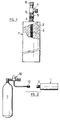
- the refrigerant device of the invention comprises a cylindrical tank 1 made of stainless steel with a length 165 mm, an internal diameter of 30.5 mm and a outer diameter of 33.7 mm, filled with a mixture 2 of 34.7 g of PICACTIF TA 90 activated carbon and 18.7 g of graphite expanded, with an initial density of 0.04, recompressed.
- a small cylinder 3 formed of a fine mesh grid, extending from one end to the other of tank, intended to provide easy access of adsorbable gas to all parts of the adsorbent material.
- An orifice 4 is provided at one of the ends of the cylinder and the female part 5 of a self-sealing quick coupling is welded around this orifice.
- the male part 6 of the quick coupling is on its side welded to a valve 7 whose tare is adjustable by a button 8.
- the male part and the part female connector are shown in position connection.
- the fitting used supplied by the STAUBLI company, included a 5.5 SPM fitting (part female) and an SPM 5.5 nozzle (male part).
- the adjustable tare valve (between 0 and 15 bar), designation 316 L, came from the American company NUPRO.
- Figure 2 schematically illustrates the recharging of the Figure 1 device.
- the reservoir 1 is connected to the pressure reducer 10 of a bottle 11 of adsorbable gas (CO 2 for example) under pressure, by connecting the female part 5, integral with the reservoir 1, to a male part 12 for quick coupling, similar to the male part 6, connected to the regulator 10. It then suffices to open the regulator for recharging to take place. Once the recharge is complete, the regulator is closed, parts 5 and 12 are disconnected, and parts 5 and 6 are reconnected after closing the valve 7.
- CO 2 adsorbable gas
- the device was charged with CO 2 until the internal pressure in the adsorber was 8.8 bar for an outside temperature of 13 ° C.
- the setting (opening pressure) of the valve was set at 1.3 bar.
- the temperatures T 1 and T 2 were measured at two different locations on the wall of the tank, one (T 1 ) located near the end of the tank where the orifice 4 of the tank is located and the other ( T 2 ) located near the other end of the tank 1.
- the device was charged with CO 2 until the internal pressure in the adsorber was 8.2 bars for an ambient temperature of 12 ° C.
- valve calibration was adjusted manually according to the temperature of the wall of so as to maintain the temperature of the wall in the vicinity of 6-7 ° C.
Landscapes
- Engineering & Computer Science (AREA)
- Physics & Mathematics (AREA)
- Mechanical Engineering (AREA)
- Thermal Sciences (AREA)
- General Engineering & Computer Science (AREA)
- Chemical & Material Sciences (AREA)
- Combustion & Propulsion (AREA)
- Chemical Kinetics & Catalysis (AREA)
- Filling Or Discharging Of Gas Storage Vessels (AREA)
- Devices That Are Associated With Refrigeration Equipment (AREA)
- Sorption Type Refrigeration Machines (AREA)
- Separation Of Gases By Adsorption (AREA)
- Cold Air Circulating Systems And Constructional Details In Refrigerators (AREA)
- Solid-Sorbent Or Filter-Aiding Compositions (AREA)
Claims (12)
- Verfahren zur Erzeugung von Kälte durch Desorption eines unter Druck stehenden Gases, das zuvor in einem in einem Behälter enthaltenen adsorbierenden Material adsorbiert wurde, dadurch gekennzeichnet, daß man das Gas unter einem gesteuerten Druck desorbiert, der über dem atmosphärischen Druck liegt, und daß das desorbierte Gas in die Atmosphäre abgelassen oder in einer Falle aufgefangen wird.
- Verfahren nach Anspruch 1, dadurch gekennzeichnet, daß das adsorbierbare Gas Kohlendioxid ist.
- Verfahren nach Anspruch 1 oder 2, dadurch gekennzeichnet, daß das Gas bei einem im wesentlichen konstanten Druck desorbiert wird.
- Verfahren nach Anspruch 1 oder 2, dadurch gekennzeichnet, daß das Gas bei einem veränderlichen Druck desorbiert wird, dessen Änderung in Abhängigkeit von einer gegebenen Temperatur reguliert wird.
- Verfahren nach Anspruch 1, dadurch gekennzeichnet, daß das adsorbierende Material mit einem gut wärmeleitenden Material gemischt wird.
- Verfahren nach einem der Ansprüche 1 bis 5, dadurch gekennzeichnet, daß das adsorbierbare Gas eines der Bestandteile eines Systems von mehreren adsorbierten Substanzen ist.
- Kühlvorrichtung, bestehend aus einem druckfesten Behälter (1), der mit einem adsorbierenden Material (2) gefüllt ist und in dem die Kälte durch Desorption eines zuvor in diesem adsorbierenden Material adsorbierten Gases erzeugt wird, dadurch gekennzeichnet, daß sie außerdem ein Ventil (7) mit einstellbarer Vorspannung aufweist, dessen Durchgang einerseits mit dem Inneren des Behälters und andererseits direkt mit dem Äußeren in Verbindung ist, sowie Mittel (5, 6) zur zeitweiligen Verbindung des Behälters mit einer unter Druck stehenden Quelle (10, 11) für ein von diesem adsorbierenden Material adsorbierbares Gas.
- Vorrichtung nach Anspruch 7, dadurch gekennzeichnet, daß diese Mittel aus einer zweiteiligen selbstschließenden Schnellkupplung bestehen, von der ein Teil am Behälter und der andere Teil am Ventil befestigt ist, so daß der Behälter vom Ventil getrennt und an die unter Druck stehende Quelle angeschlossen werden kann, um mit adsorbierbarem Gas gefüllt zu werden.
- Vorrichtung nach Anspruch 7 oder 8, dadurch gekennzeichnet, daß die Quelle eine Kohlendioxidquelle ist.
- Vorrichtung nach Anspruch 7, 8 oder 9, dadurch gekennzeichnet, daß das adsorbierende Material aus Fasern aus aktiviertem Kohlenstoff und Aktivkohlen ausgewählt ist.
- Vorrichtung nach einem der Ansprüche 7 bis 8, dadurch gekennzeichnet, daß sie außerdem ein kleines perforiertes Rohr oder ein Gitterrohr (3) aufweist, das sich von der an einem Ende des Behälters vorgesehenen Einlaßöffnung für das adsorbierbare Gas bis zum entgegengesetzten Ende des Behälters erstreckt.
- Vorrichtung nach Anspruch 7 oder 10, dadurch gekennzeichnet, daß das adsorbierende Material mit einem gut wärmeleitenden Material gemischt ist.
Applications Claiming Priority (1)
| Application Number | Priority Date | Filing Date | Title |
|---|---|---|---|
| PCT/FR1995/001307 WO1997014004A1 (fr) | 1995-10-06 | 1995-10-06 | Procede et dispositif frigorigenes |
Publications (2)
| Publication Number | Publication Date |
|---|---|
| EP0797752A1 EP0797752A1 (de) | 1997-10-01 |
| EP0797752B1 true EP0797752B1 (de) | 2000-02-09 |
Family
ID=9475842
Family Applications (1)
| Application Number | Title | Priority Date | Filing Date |
|---|---|---|---|
| EP95934182A Expired - Lifetime EP0797752B1 (de) | 1995-10-06 | 1995-10-06 | Kälte-verfahren und -vorrichtung |
Country Status (13)
| Country | Link |
|---|---|
| US (1) | US5842350A (de) |
| EP (1) | EP0797752B1 (de) |
| JP (1) | JP3687978B2 (de) |
| KR (1) | KR100287983B1 (de) |
| AT (1) | ATE189740T1 (de) |
| AU (1) | AU700791B2 (de) |
| CA (1) | CA2233718C (de) |
| DE (1) | DE69515067T2 (de) |
| DK (1) | DK0797752T3 (de) |
| ES (1) | ES2141963T3 (de) |
| GR (1) | GR3032710T3 (de) |
| PT (1) | PT797752E (de) |
| WO (1) | WO1997014004A1 (de) |
Families Citing this family (10)
| Publication number | Priority date | Publication date | Assignee | Title |
|---|---|---|---|---|
| GB9801435D0 (en) * | 1998-01-24 | 1998-03-18 | Bass Plc | Improvements relating to containers |
| US6103280A (en) * | 1997-09-20 | 2000-08-15 | Bass Public Limited Company | Self-cooling containers of beverage and foodstuffs |
| US6427451B2 (en) * | 1999-06-08 | 2002-08-06 | W. L. Gore & Associates (Uk) Ltd. | Material for the controlled vaporization of a liquid cryogen |
| CH710862B1 (de) | 1999-11-26 | 2016-09-15 | Imerys Graphite & Carbon Switzerland Sa | Verfahren zur Herstellung von Graphitpulvern mit erhöhter Schüttdichte. |
| GB0023380D0 (en) * | 2000-09-23 | 2000-11-08 | Sutcliffe Speakman Carbons Ltd | An improved composition and apparatus for transferring heat to or from fluids |
| WO2004043180A1 (en) * | 2002-11-14 | 2004-05-27 | Dorimi S.R.L. | Cooling system for garments |
| KR101524324B1 (ko) * | 2007-06-22 | 2015-06-04 | 인티그리스, 인코포레이티드 | 태양열 흡착식 냉각 시스템용 구성요소 및 그 구성요소 제조 방법 |
| EP2630420B1 (de) | 2010-10-20 | 2014-12-17 | Coldway | Thermochemisches system mit einem modularen anschluss |
| FR2966573A1 (fr) * | 2010-10-20 | 2012-04-27 | Coldway | Systeme thermochimique a connexion modulaire |
| BR112015007926A2 (pt) * | 2012-10-15 | 2017-07-04 | Joseph Company Int Inc | unidade de troca de calor para recipiente autorrefrigerante de bebidas |
Family Cites Families (18)
| Publication number | Priority date | Publication date | Assignee | Title |
|---|---|---|---|---|
| DE442923C (de) * | 1924-03-04 | 1927-04-09 | Senssenbrenner G M B H C | Verfahren zum Betriebe von Absorptionskuehlanlagen in Eisenbahnwagen |
| US1729083A (en) * | 1925-03-11 | 1929-09-24 | Silica Gel Corp | Refrigeration process and apparatus |
| FR744759A (de) * | 1931-11-01 | 1933-04-26 | ||
| US2253907A (en) * | 1936-12-15 | 1941-08-26 | Julius Y Levine | Refrigerating apparatus |
| FR982202A (fr) * | 1949-01-17 | 1951-06-07 | Appareil de réfrigération, à absorption | |
| FR2172754A1 (en) * | 1972-02-21 | 1973-10-05 | Greiner Leonard | Heating and cooling apparatus with absorption chemical - and fluid to be absorbed |
| SE7706357L (sv) * | 1977-05-31 | 1978-12-01 | Brunberg Ernst Ake | Sett vid kylning av ett utrymme samt anordning for genomforande av settet |
| US4126016A (en) * | 1977-07-27 | 1978-11-21 | Leonard Greiner | Vacuum interconnect for heating and cooling unit |
| FR2489488A1 (fr) * | 1980-08-29 | 1982-03-05 | Blaizat Claude | Procede et dispositif de refrigeration |
| US4993239A (en) * | 1987-07-07 | 1991-02-19 | International Thermal Packaging, Inc. | Cooling device with improved waste-heat handling capability |
| AU627295B2 (en) * | 1989-03-08 | 1992-08-20 | Rocky Research | Method and apparatus for achieving high reaction rates in solid-gas reactor systems |
| DE4003107A1 (de) * | 1990-02-02 | 1991-08-08 | Zeolith Tech | Eiserzeuger nach dem sorptionsprinzip |
| US5111668A (en) * | 1990-10-05 | 1992-05-12 | Mainstream Engineering Corp. | Cooling device and method for hazardous materials suits |
| US5165247A (en) * | 1991-02-11 | 1992-11-24 | Rocky Research | Refrigerant recycling system |
| GB9115140D0 (en) * | 1991-07-13 | 1991-08-28 | Boc Group Plc | Improvements in refrigerators |
| FR2708724B1 (fr) * | 1993-07-29 | 1995-10-13 | Boye Sa Manuf Vetements Paul | Production de froid par adsoption/desorption de dioxyde de carbone avec utilisation de fibres de carbone activé ou de charbon actif comme matière adsorbante. |
| FR2719367B1 (fr) * | 1994-04-27 | 1996-06-21 | Boye Sa Manuf Vetements Paul | Procédé et dispositif frigorigènes. |
| GB9513606D0 (en) * | 1995-07-04 | 1995-09-06 | Boc Group Plc | Apparatus for chilling fluids |
-
1995
- 1995-10-06 EP EP95934182A patent/EP0797752B1/de not_active Expired - Lifetime
- 1995-10-06 AU AU36569/95A patent/AU700791B2/en not_active Ceased
- 1995-10-06 DK DK95934182T patent/DK0797752T3/da active
- 1995-10-06 KR KR1019980702540A patent/KR100287983B1/ko not_active Expired - Fee Related
- 1995-10-06 PT PT95934182T patent/PT797752E/pt unknown
- 1995-10-06 US US08/849,379 patent/US5842350A/en not_active Expired - Fee Related
- 1995-10-06 JP JP51475097A patent/JP3687978B2/ja not_active Expired - Fee Related
- 1995-10-06 ES ES95934182T patent/ES2141963T3/es not_active Expired - Lifetime
- 1995-10-06 CA CA002233718A patent/CA2233718C/en not_active Expired - Fee Related
- 1995-10-06 AT AT95934182T patent/ATE189740T1/de not_active IP Right Cessation
- 1995-10-06 WO PCT/FR1995/001307 patent/WO1997014004A1/fr not_active Ceased
- 1995-10-06 DE DE69515067T patent/DE69515067T2/de not_active Expired - Fee Related
-
2000
- 2000-02-18 GR GR20000400409T patent/GR3032710T3/el not_active IP Right Cessation
Also Published As
| Publication number | Publication date |
|---|---|
| GR3032710T3 (en) | 2000-06-30 |
| DE69515067D1 (de) | 2000-03-16 |
| CA2233718A1 (en) | 1997-04-17 |
| EP0797752A1 (de) | 1997-10-01 |
| DK0797752T3 (da) | 2000-05-15 |
| AU700791B2 (en) | 1999-01-14 |
| JPH11513476A (ja) | 1999-11-16 |
| DE69515067T2 (de) | 2002-03-14 |
| CA2233718C (en) | 2005-12-06 |
| WO1997014004A1 (fr) | 1997-04-17 |
| ES2141963T3 (es) | 2000-04-01 |
| US5842350A (en) | 1998-12-01 |
| JP3687978B2 (ja) | 2005-08-24 |
| KR19990064061A (ko) | 1999-07-26 |
| PT797752E (pt) | 2000-06-30 |
| ATE189740T1 (de) | 2000-02-15 |
| AU3656995A (en) | 1997-04-30 |
| KR100287983B1 (ko) | 2001-05-02 |
Similar Documents
| Publication | Publication Date | Title |
|---|---|---|
| EP0797752B1 (de) | Kälte-verfahren und -vorrichtung | |
| EP0109361A1 (de) | Schubregler | |
| FR2719367A1 (fr) | Procédé et dispositif frigorigènes. | |
| CA1110860A (fr) | Appareil a glacer ou givrer ou embuer les recipients ou corps creux, notamment les verres | |
| FR2470321A1 (fr) | Vanne | |
| CA2679351A1 (fr) | Dispositif et procede de refroidissement de boissons | |
| FR2672960A1 (fr) | Accouplement pour canalisations ou tuyaux isoles sous vide notamment pour remplissage d'hydrogene liquide dans des reservoirs de vehicule. | |
| EP0608176A1 (de) | Gerät zum Verteilen von Nebel | |
| CA1197107A (fr) | Dispositif de regulation d'un refrigerateur a effet joule-thomson | |
| FR2586793A1 (fr) | Procede et appareil de refrigeration magnetique | |
| FR3104671A1 (fr) | Dispositif de distribution de carburant gazeux | |
| FR2888124A1 (fr) | Extincteur a brouillard de liquide et son utilisation | |
| FR2558735A1 (fr) | Cryopiege | |
| WO1999032818A1 (fr) | Valve monostable | |
| EP0478421B1 (de) | Dichtungsvorrichtung mit eine Flüssigkeitsdichtung | |
| WO2020074795A1 (fr) | Dispositif de séparation de liquide et de gaz et appareil thermodynamique equipé d'un tel dispositif | |
| FR2487056A1 (fr) | Procede permettant de refroidir ou de rechauffer un liquide contenu dans une citerne mobile et equipement destine a mettre en oeuvre un tel procede | |
| EP2411747A1 (de) | Vorrichtung zum schnellen kühlen von getränken | |
| FR2780143A1 (fr) | Boucle de fluide refrigerant amelioree pour installation de climatisation de vehicule | |
| FR3149366A1 (fr) | Dispositif de chauffage thermodynamique | |
| FR2747402A1 (fr) | Four a diffusion | |
| FR2894854A1 (fr) | Chambre de melange et dispositif de pulverisation comportant une telle chambre | |
| EP4589144A1 (de) | Vorrichtung und verfahren zur fluidverdichtung | |
| FR2906877A1 (fr) | Organe de detente adapte pour un fluide refrigerant a base d'un melange comprenant du 1,1,1,2-tetrafluoropropene ("hfo-1234yf") et du trifluoroiodomethane ("cf31" | |
| EP0691901A1 (de) | Verfahren und vorrichtung zum schneiden mittels eines tiefsttemperatur - flüssigkeitsstrahles |
Legal Events
| Date | Code | Title | Description |
|---|---|---|---|
| PUAI | Public reference made under article 153(3) epc to a published international application that has entered the european phase |
Free format text: ORIGINAL CODE: 0009012 |
|
| 17P | Request for examination filed |
Effective date: 19970701 |
|
| AK | Designated contracting states |
Kind code of ref document: A1 Designated state(s): AT BE CH DE DK ES GB GR IE IT LI LU MC NL PT SE |
|
| GRAG | Despatch of communication of intention to grant |
Free format text: ORIGINAL CODE: EPIDOS AGRA |
|
| 17Q | First examination report despatched |
Effective date: 19981028 |
|
| GRAG | Despatch of communication of intention to grant |
Free format text: ORIGINAL CODE: EPIDOS AGRA |
|
| GRAG | Despatch of communication of intention to grant |
Free format text: ORIGINAL CODE: EPIDOS AGRA |
|
| GRAH | Despatch of communication of intention to grant a patent |
Free format text: ORIGINAL CODE: EPIDOS IGRA |
|
| GRAH | Despatch of communication of intention to grant a patent |
Free format text: ORIGINAL CODE: EPIDOS IGRA |
|
| RAP1 | Party data changed (applicant data changed or rights of an application transferred) |
Owner name: MANUFACTURE DE VETEMENTS PAUL BOYE S.A. |
|
| GRAA | (expected) grant |
Free format text: ORIGINAL CODE: 0009210 |
|
| AK | Designated contracting states |
Kind code of ref document: B1 Designated state(s): AT BE CH DE DK ES GB GR IE IT LI LU MC NL PT SE |
|
| REF | Corresponds to: |
Ref document number: 189740 Country of ref document: AT Date of ref document: 20000215 Kind code of ref document: T |
|
| REG | Reference to a national code |
Ref country code: CH Ref legal event code: NV Representative=s name: KIRKER & CIE SA Ref country code: CH Ref legal event code: EP |
|
| REF | Corresponds to: |
Ref document number: 69515067 Country of ref document: DE Date of ref document: 20000316 |
|
| REG | Reference to a national code |
Ref country code: ES Ref legal event code: FG2A Ref document number: 2141963 Country of ref document: ES Kind code of ref document: T3 |
|
| ITF | It: translation for a ep patent filed | ||
| GBT | Gb: translation of ep patent filed (gb section 77(6)(a)/1977) |
Effective date: 20000323 |
|
| REG | Reference to a national code |
Ref country code: IE Ref legal event code: FG4D Free format text: FRENCH |
|
| REG | Reference to a national code |
Ref country code: DK Ref legal event code: T3 |
|
| REG | Reference to a national code |
Ref country code: PT Ref legal event code: SC4A Free format text: AVAILABILITY OF NATIONAL TRANSLATION Effective date: 20000407 |
|
| EN | Fr: translation not filed | ||
| EN4 | Fr: notification of non filing translation in an earlier bopi is erroneous | ||
| PLBE | No opposition filed within time limit |
Free format text: ORIGINAL CODE: 0009261 |
|
| 26N | No opposition filed | ||
| REG | Reference to a national code |
Ref country code: GB Ref legal event code: IF02 |
|
| PGFP | Annual fee paid to national office [announced via postgrant information from national office to epo] |
Ref country code: AT Payment date: 20050913 Year of fee payment: 11 |
|
| PGFP | Annual fee paid to national office [announced via postgrant information from national office to epo] |
Ref country code: NL Payment date: 20050915 Year of fee payment: 11 Ref country code: IE Payment date: 20050915 Year of fee payment: 11 |
|
| PGFP | Annual fee paid to national office [announced via postgrant information from national office to epo] |
Ref country code: SE Payment date: 20050916 Year of fee payment: 11 |
|
| PGFP | Annual fee paid to national office [announced via postgrant information from national office to epo] |
Ref country code: MC Payment date: 20050919 Year of fee payment: 11 |
|
| PGFP | Annual fee paid to national office [announced via postgrant information from national office to epo] |
Ref country code: DK Payment date: 20050920 Year of fee payment: 11 |
|
| PGFP | Annual fee paid to national office [announced via postgrant information from national office to epo] |
Ref country code: LU Payment date: 20050923 Year of fee payment: 11 Ref country code: GB Payment date: 20050923 Year of fee payment: 11 |
|
| PGFP | Annual fee paid to national office [announced via postgrant information from national office to epo] |
Ref country code: GR Payment date: 20050927 Year of fee payment: 11 |
|
| PGFP | Annual fee paid to national office [announced via postgrant information from national office to epo] |
Ref country code: PT Payment date: 20051006 Year of fee payment: 11 |
|
| PGFP | Annual fee paid to national office [announced via postgrant information from national office to epo] |
Ref country code: DE Payment date: 20051007 Year of fee payment: 11 |
|
| PGFP | Annual fee paid to national office [announced via postgrant information from national office to epo] |
Ref country code: ES Payment date: 20051013 Year of fee payment: 11 Ref country code: CH Payment date: 20051013 Year of fee payment: 11 |
|
| PGFP | Annual fee paid to national office [announced via postgrant information from national office to epo] |
Ref country code: BE Payment date: 20051031 Year of fee payment: 11 |
|
| PG25 | Lapsed in a contracting state [announced via postgrant information from national office to epo] |
Ref country code: IE Free format text: LAPSE BECAUSE OF NON-PAYMENT OF DUE FEES Effective date: 20061006 Ref country code: AT Free format text: LAPSE BECAUSE OF NON-PAYMENT OF DUE FEES Effective date: 20061006 |
|
| PG25 | Lapsed in a contracting state [announced via postgrant information from national office to epo] |
Ref country code: SE Free format text: LAPSE BECAUSE OF NON-PAYMENT OF DUE FEES Effective date: 20061007 |
|
| PG25 | Lapsed in a contracting state [announced via postgrant information from national office to epo] |
Ref country code: MC Free format text: LAPSE BECAUSE OF NON-PAYMENT OF DUE FEES Effective date: 20061031 Ref country code: LI Free format text: LAPSE BECAUSE OF NON-PAYMENT OF DUE FEES Effective date: 20061031 Ref country code: DK Free format text: LAPSE BECAUSE OF NON-PAYMENT OF DUE FEES Effective date: 20061031 Ref country code: CH Free format text: LAPSE BECAUSE OF NON-PAYMENT OF DUE FEES Effective date: 20061031 |
|
| PGFP | Annual fee paid to national office [announced via postgrant information from national office to epo] |
Ref country code: IT Payment date: 20061031 Year of fee payment: 12 |
|
| PG25 | Lapsed in a contracting state [announced via postgrant information from national office to epo] |
Ref country code: PT Free format text: LAPSE BECAUSE OF NON-PAYMENT OF DUE FEES Effective date: 20070409 |
|
| REG | Reference to a national code |
Ref country code: PT Ref legal event code: MM4A Free format text: LAPSE DUE TO NON-PAYMENT OF FEES Effective date: 20070409 |
|
| PG25 | Lapsed in a contracting state [announced via postgrant information from national office to epo] |
Ref country code: NL Free format text: LAPSE BECAUSE OF NON-PAYMENT OF DUE FEES Effective date: 20070501 Ref country code: DE Free format text: LAPSE BECAUSE OF NON-PAYMENT OF DUE FEES Effective date: 20070501 |
|
| REG | Reference to a national code |
Ref country code: CH Ref legal event code: PL |
|
| EUG | Se: european patent has lapsed | ||
| GBPC | Gb: european patent ceased through non-payment of renewal fee |
Effective date: 20061006 |
|
| NLV4 | Nl: lapsed or anulled due to non-payment of the annual fee |
Effective date: 20070501 |
|
| REG | Reference to a national code |
Ref country code: IE Ref legal event code: MM4A |
|
| PG25 | Lapsed in a contracting state [announced via postgrant information from national office to epo] |
Ref country code: GB Free format text: LAPSE BECAUSE OF NON-PAYMENT OF DUE FEES Effective date: 20061006 |
|
| BERE | Be: lapsed |
Owner name: MANUFACTURE DE VETEMENTS PAUL *BOYE S.A. Effective date: 20061031 |
|
| REG | Reference to a national code |
Ref country code: ES Ref legal event code: FD2A Effective date: 20061007 |
|
| PG25 | Lapsed in a contracting state [announced via postgrant information from national office to epo] |
Ref country code: ES Free format text: LAPSE BECAUSE OF NON-PAYMENT OF DUE FEES Effective date: 20061007 |
|
| PG25 | Lapsed in a contracting state [announced via postgrant information from national office to epo] |
Ref country code: LU Free format text: LAPSE BECAUSE OF NON-PAYMENT OF DUE FEES Effective date: 20061006 |
|
| PG25 | Lapsed in a contracting state [announced via postgrant information from national office to epo] |
Ref country code: GR Free format text: LAPSE BECAUSE OF NON-PAYMENT OF DUE FEES Effective date: 20070503 |
|
| PG25 | Lapsed in a contracting state [announced via postgrant information from national office to epo] |
Ref country code: IT Free format text: LAPSE BECAUSE OF NON-PAYMENT OF DUE FEES Effective date: 20071006 Ref country code: BE Free format text: LAPSE BECAUSE OF FAILURE TO SUBMIT A TRANSLATION OF THE DESCRIPTION OR TO PAY THE FEE WITHIN THE PRESCRIBED TIME-LIMIT Effective date: 20061031 |