EP0797171B1 - Méthode et appareil de traitement d'image - Google Patents
Méthode et appareil de traitement d'image Download PDFInfo
- Publication number
- EP0797171B1 EP0797171B1 EP97301798A EP97301798A EP0797171B1 EP 0797171 B1 EP0797171 B1 EP 0797171B1 EP 97301798 A EP97301798 A EP 97301798A EP 97301798 A EP97301798 A EP 97301798A EP 0797171 B1 EP0797171 B1 EP 0797171B1
- Authority
- EP
- European Patent Office
- Prior art keywords
- image
- viewpoint position
- line
- data
- viewpoint
- Prior art date
- Legal status (The legal status is an assumption and is not a legal conclusion. Google has not performed a legal analysis and makes no representation as to the accuracy of the status listed.)
- Expired - Lifetime
Links
Images


Classifications
-
- G—PHYSICS
- G06—COMPUTING; CALCULATING OR COUNTING
- G06T—IMAGE DATA PROCESSING OR GENERATION, IN GENERAL
- G06T15/00—3D [Three Dimensional] image rendering
- G06T15/10—Geometric effects
Definitions
- the present invention relates to image processing to generate and output an image at a viewpoint position for an observer on the basis of a plurality of input images at different viewpoints.
- the three-dimensional shape or the like of an object is temporarily reconstructed using, e.g., stereoscopic distance measurements, and an image observed from the new viewpoint position is generated using the reconstructed shape.
- the object has a simple shape, its shape may be reconstructed by calculating corresponding points by, e.g., stereoscopic distance measurements but it is nearly impossible for natural objects such as trees having complex shapes to attain such reconstruction. Therefore, the method of calculating the three-dimensional shape and generating an image at a new viewpoint position based on the calculated shape cannot be used for such natural objects.
- a Viewpoint Dependent Stereoscopic Display Using Interpolation of Multi-Viewpoint Images discloses a method of autostereoscopic display which can show viewpoint dependent images according to viewer's movement.
- This display system consists of a computer, a head tracking device, and a binocular stereoscopic display.
- interpolation and reconstruction of multi-viewpoint images provide a viewer, with unlimited number of images according to his/her smooth movement.
- the present invention provides an image processing apparatus as set out in claim 1.
- the present invention also provides an image processing apparatus as set out in claim 5.
- the present invention also provides an image processing method as set out in claim 9.
- the present invention also provides an image processing method as set out in claim 12.
- the present invention also provides a computer program product as set out in claim 15.
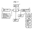
- Fig. 1 is a block diagram showing the arrangement of an image processing apparatus of the first background example, and showing the arrangement of the overall system of the apparatus of this background example.
- an image input unit 11 inputs multi-viewpoint images obtained by taking images of an object from a plurality of viewpoint positions.
- the image input unit 11 may comprise a plurality of image sensing systems or may obtain multi-viewpoint images by moving an image sensing system.
- a central processing unit (CPU) 13 comprises a microprocessor for executing various kinds of processing (to be described later) in accordance with the processing procedures pre-stored in a memory unit 14, which comprises a ROM, hard disk, or the like for storing programs and data for controlling the CPU 13.
- a memory medium reader 15 reads programs and data stored in an FD (floppy disk), HD (hard disk), CD-ROM, ROM, magnetic tape, optical disk, and the like.
- An input unit 16 inputs commands and data to the CPU 13.
- a display unit 17 serves as a monitor for displaying various kinds of information and associated information during or after the processing of the CPU 13.
- a viewpoint position and direction of line of sight detector 12 detects the viewpoint position and the direction of line of sight of the observer.
- the viewpoint position and direction of line of sight detector may comprise a known one.
- Fig. 2 is a flow chart showing the basic processing of the image processing apparatus of the first background example. This processing is executed by the CPU 13.
- the CPU 13 executes processing in accordance with the processing procedures (programs) stored in the memory unit 14.
- the image input unit 11 inputs multi-viewpoint images taken at multi-viewpoint positions arranged in line, and the viewpoint positions of the image input unit 11 at which these multi-viewpoint images are taken are detected and read, in step S21.
- these multi-viewpoint images and their viewpoint position information are stored in the memory unit 14 in correspondence with each other.
- step S23 and the subsequent steps the processing for reading out the multi-viewpoint image data and the viewpoint position data of the observer upon taking these images and reconstructing an image observed from an arbitrary viewpoint position is executed.
- step S23 the viewpoint position and direction of line of sight detector 12 detects the viewpoint position and the direction of line of sight of the observer who observes the screen of the display unit 17 as a monitor.
- step S24 multi-viewpoint image data are read out from the memory unit 14 on the basis of the detected viewpoint position information.
- step S25 an image to be observed from the viewpoint position is reconstructed using the readout multi-viewpoint image data.
- step S26 the reconstructed image observed from the arbitrary viewpoint position is displayed on the display unit 17.
- stereoscopic viewing can be attained using a lenticular display or the like even when the observer changes his or her viewpoint position.
- the above-mentioned program may be stored in a memory medium such as an HD (hard disk), FD (floppy disk), CD-ROM, ROM, magnetic tape, or the like, may be read out by the memory medium reader 15, and may be stored in the memory unit 14.
- a memory medium such as an HD (hard disk), FD (floppy disk), CD-ROM, ROM, magnetic tape, or the like
- step S25 in the flow chart in Fig. 2 will be explained in detail below.
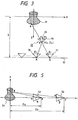
- Fig. 3 shows the principle of reconstructing an image from an arbitrary viewpoint position using multi-viewpoint images input by the image input unit 11 of the image processing apparatus according to the first background example.
- Fig. 3 illustrates an object 31, a line 32 with projection viewpoints, which line connects the image sensing positions of a plurality of input images (phototaking positions of a camera), a virtual camera 33 set at an arbitrary observation position P (x', z'), an image sensing plane 34 of an image sensing element (CCD) of the virtual camera 33 set at the position P (x', z'), and an image 35 at the observation position P (x', z') formed on the virtual image sensing plane 34, i.e., at the viewpoint position.
- a line 32 with projection viewpoints which line connects the image sensing positions of a plurality of input images (phototaking positions of a camera)
- a virtual camera 33 set at an arbitrary observation position P (x', z')
- an image sensing plane 34 of an image sensing element (CCD) of the virtual camera 33 set at the position P (x', z')
- an image 35 at the observation position P (x', z') formed on the virtual
- the image sensing plane 34 cf the virtual camera 33 is imaginarily illustrated on the object side with respect to the observation position for the sake of easy understanding since the screen upon observing the object 31 at the observation position P is assumed. However, in practice, if the observation position P is assumed to be the center of the camera, the image sensing plane is present on the side opposite to the object with respect to the observation position P.
- Fig. 3 also illustrates an image 36 at a z-observation position on the actual line 32 with projection viewpoints, i.e., a viewpoint position R, and an image 37 at a viewpoint position Q on the line 32 with projection viewpoints.
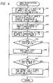
- step S25 in the flow chart in Fig. 2 will be described below with reference to Fig. 3 above and the flow chart in Fig. 4.
- i represents the pixel, in the horizontal direction, on the screen
- j represents the line in the vertical direction.
- step S41 a target line j is set at the head line of an image P, and a target pixel i is set at the pixel at the left end of the line j.
- step S42 the position of an image Q in the line 32 with projection viewpoints corresponding to the i-th pixel of the line j of an image P is calculated.
- This position can be calculated as follows. Assume that a certain point A is imaged at a pixel position Pi of the virtual camera at the viewpoint position P. Also, assume that Q represents the intersection between a line connecting the positions A and P, and the line 32 with projection viewpoints.
- the object imaged at the pixel position Pi is equivalent to that imaged at a pixel position Qi of the image taken at the viewpoint position Q.
- the X-coordinate x of the viewpoint position Q can be expressed by equation (1) below.
- the central pixel position of the scan line is assumed to be the Oth pixel.
- x x' + i•d•(g - z')/f
- d the pixel pitch of the virtual image sensing plate 34 of the virtual camera 33
- f the focal length
- g the distance from the origin to the line 32 with projection viewpoints.
- the object imaged at a pixel position Pj of the virtual camera at the viewpoint position P is equivalent to that imaged at a pixel position Rj of an image at a viewpoint position R stored in the memory unit 14.
- step S43 the line number of the image Q corresponding to the line j of the image P is calculated. The method of calculating the line number of the image Q will be described below with reference to Fig. 5.
- Fig. 5 shows the principle of correcting distortion of the image reconstructed by the processing in step S25 in the image processing apparatus of the first background example.
- Fig. 5 illustrates an object 51, an image 52 to be reconstructed at an arbitrary viewpoint position P, and an image 53 at a viewpoint position S on the line 32 with projection viewpoints.
- a given point B in the object 51 will be examined. Assume that the point B is close to the Y-axis, the Z-coordinate values Pz and Sz of the image 52 to be reconstructed at the viewpoint position P and the image 53 at the viewpoint position S on the line 32 with projection viewpoints are sufficiently large, or the Z-coordinate value Pz of the image 52 to be reconstructed at the viewpoint position P is nearly equal to the Z-coordinate value Sz of the image 53 at the viewpoint position S on the line 32 with projection viewpoints. In this case, light rays coming from the point B are recorded on the m-th line in the image 52 to be reconstructed at the viewpoint position P, and the n-th line in the image 53 at the viewpoint position S on the line 32 with projection viewpoints.
- step S44 the value of the i-th pixel of the line n of the image Q is copied to the i-th pixel of the line j of the image P.
- step S45 image distortion upon reconstructing the image at the viewpoint position, which is not on the line 32 with projection viewpoints can be suppressed to some extent.
- step S45 the flow advances to step S45 to check if processing for all the pixels in the target line j is complete.
- step S45 the flow advances to step S47; otherwise, the flow advances to step S46.
- step S46 the target pixel i is moved to the right neighboring pixel, and the flow returns to step S42.
- step S47 it is checked if the processing for all the lines in the image P is complete. If YES in step S47, this subroutine ends and returns to step S26 in the flow chart in Fig. 2; otherwise, the target line j is moved to the next line and the target pixel i is set at the left end of the line j in step S48. Thereafter, the flow returns to step S42.
- the first background example has a limitation that the viewpoint positions of input multi-viewpoint images must be arranged in line. A method that can remove this limitation will be explained below.
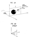
- an image that can be viewed from a viewpoint position P falling within a range z ⁇ 0 in the three-dimensional space is equivalent to an image obtained by sampling only light rays that pass P from the set of light rays that pass through the reference plane 61 (see Fig. 7).
- each light ray is expressed by a position (x, y) where it passes through the reference plane 61, angles ⁇ and ⁇ the light ray makes with the X- and Y-axes, time t at which the light ray passes through the plane, and a color (r, g, b) of the light ray.
- the object is assumed to be a still object and to have no parallax in the Y-axis direction since the computation volume and data volume become huge if all these data are used.
- a linear path is calculated based on images obtained at a large number of viewpoint positions, and it is assumed that the x-u plane is filled with these paths at high density.
- an image at a viewpoint position Q falling within the range z ⁇ 0 can be obtained by calculating the paths of light rays that pass the position Q on the x-u plane and acquiring the colors of light rays already recorded on the paths, as shown in Fig. 10.
- processing is attained by mapping multi-viewpoint images on the x-u plane, an image can be reconstructed even when the viewpoint positions of input images are not arranged in line.
- processing is performed in units of scan lines as in the first background example. That is, the first line of an image at a given viewpoint position to be generated is generated using the first lines of input multi-viewpoint images, and the j-th line of the image at the viewpoint position to be generated is generated using the j-th lines of input multi-viewpoint images.
- the first line of an image at a given viewpoint position to be generated is generated using the first lines of input multi-viewpoint images
- the j-th line of the image at the viewpoint position to be generated is generated using the j-th lines of input multi-viewpoint images.
- the correspondences between points on the paths and the input multi-viewpoint images are checked. From the distance Sz from the phototaking position of the image to the reference plane and the distance Pz from the position of the image to be generated to the reference plate, a corresponding line is calculated in accordance with equation (5) above, and the image is generated using the calculated line.
- N represents the number of lines of the image
- m represents the position of the target line
- n represents the line position in the corresponding image. If n assumes a value which is nonexistent, the value of the image to be generated is set to be a predetermined value.
- the line position in a required multi-viewpoint image is calculated in correspondence with the position of the image to be generated and the position of a multi-viewpoint image that includes light rays required for generating the image, and the calculated line is used, thus suppressing distortion of the generated image.
- the position of a scan line required for generating the image is calculated on the basis of the viewpoint position of the observer and the viewpoint position of an input image required for generating the image, and is used in generating the image. In this manner, a distortion-free image can be generated.
- a stereoscopic image can be reconstructed using images corresponding to the right and left viewpoints using a plurality of pieces of image information taken at multiple viewpoints, and an image processing apparatus with a broad application range can be realized.
- An image observed from an arbitrary viewpoint position is generated from a plurality of pieces of image information taken at multiple viewpoint positions, and distortion caused upon generating an image can be eliminated, thus obtaining a natural image.
- An image with a view from an arbitrary viewpoint position can be easily generated from a plurality of pieces of image information taken at multiple viewpoint positions, and various kinds of image processing can be performed without increasing the calculation scale and required memory capacity.
- the viewpoint position range that allows observation is limited to the range z ⁇ 0 and, hence, the observation range within which movement of the viewpoint position is allowed is narrow.
- the three-dimensional space is expressed by a single x-u space, if ⁇ is nearly equal to ⁇ 90° (or if the reference plane and light rays that pass through the reference plane are nearly parallel to each other), tan ⁇ diverges, and an infinitely broad x-u space, i.e., a huge data volume, is required.
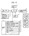
- Fig. 11 is a block diagram showing the image processing apparatus according to the first embodiment of the present invention.
- a memory unit 14 stores the number 14b of reference planes, a viewpoint position 14c, a direction 14d of line of sight, an image size 14e, an angle 14f of view, an image parameter 14g, an image 14h, and the like in addition to a program 14a for controlling a CPU 13.
- Fig. 12 is an explanatory view of the method of acquiring multi-viewpoint images in an image input unit 11 of the image processing apparatus of the first embodiment.
- Fig. 12 illustrates an object 121 to be phototaken, a rotary table 122 which rotates while placing the object 121 thereon, so as to take images of the object 121 from its surrounding positions, and a CCD camera 123 used for taking images of the object 121.
- Multi-viewpoint images are taken by the CCD camera 123 while rotating the object 121 placed on the rotary table 122.
- the multi-viewpoint images taken by the CCD camera 123 are stored in the memory unit 14.
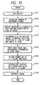
- Fig. 13 is a flow chart showing the flow of the processing of the image processing apparatus of the first embodiment.
- step S131 the work area, variables to be used, and the like in the memory unit 14 are initialized in step S131.
- step S132 the number of reference planes of the light space and their layout are determined.
- predetermined values may be used or an operator may input these values from an input unit 16 at the beginning of the processing.
- the number of reference planes may be set in correspondence with the limited region.
- the present invention is not limited to the above-mentioned method.
- n of reference planes can be any integer that satisfies n > 1.
- Arranging the reference planes radially is to arrange the reference planes, so that all the reference planes cross on a single line (the Y-axis in this case) which passes through an object, the angles adjacent reference planes make equal each other, and one of the reference plane makes an angle ⁇ /2 (where ⁇ is the angle adjacent reference planes make) with the Z-axis. Then, the angles the reference planes arranged in this manner make with light rays which pass through the reference planes are checked, and light rays are recorded in a light space corresponding to the reference plane that makes an angle closest to right angles.
- a case will be exemplified wherein four radially arranged reference planes are used. In Fig.
- a first reference plane 141 corresponds to a light space which records the paths of light rays which come from the object 121 and have angles falling within the range 0° ⁇ ⁇ ⁇ 90°.
- a second reference plane 142 corresponds to a light space which records the paths of light rays which come from the object 121 and have angles falling within the range 90° ⁇ ⁇ ⁇ 180°.
- a third reference plane 143 corresponds to a light space which records the paths of light rays which come from the object 121 and have angles falling within the range 180° ⁇ ⁇ ⁇ 270°.
- a fourth reference plane 144 corresponds to a light space which records the paths of light rays which come from the object 121 and have angles falling within the range 270° ⁇ ⁇ ⁇ 360°.
- the viewpoint position and direction of line of sight are detected by the viewpoint position and direction of line of sight detector 12 in step S133.
- the viewpoint position and direction of line of sight detector 12 is used.
- the present invention is not limited to this specific means, and another means for inputting a desired image (the viewpoint position and direction of line of sight) of the operator may be used.
- step S134 the size and angle of view of the image to be generated are determined. These values may be input by the operator using the input unit 16 or values pre-stored in the memory unit 14 may be used. Alternatively, these values may be determined in correspondence with the resolution of the display unit 17 or the processing performance of the CPU 13, and the present invention is not limited to the above specific means.
- step S135 multi-viewpoint data stored in the memory unit 14 and parameters (the direction ⁇ of the optical axis, the angle ⁇ of view, the number N of pixels, in the scan line direction, of the CCD, the number M of lines, and the phototaking position (x, z)) upon taking images are extracted.
- the direction ⁇ of light rays that pass the lens center of the camera and the individual pixels of the CCD are calculated, and one of the four reference planes in which the corresponding light ray is to be recorded is determined based on the values ⁇ .
- equations (6) and (7) the colors of light rays, the numbers of original multi-viewpoint images corresponding to the light rays, and the pixel numbers are recorded in the x-u space corresponding to the determined reference plane.
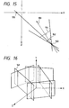
- Fig. 15 illustrates an optical axis 151 of a camera, an angle 152 of view of the camera, a lens center 153 of the camera, a CCD surface 154 of the camera, and an intersection 155 between a line connecting the i-th pixel on the CCD surface 154 and the lens center 153, and the X-axis.
- step S136 after step S135 will be described in detail below with reference to Fig. 15.
- (x, z) is the position of the lens center 153 of the camera
- ⁇ is the direction of the optical axis 151 of the camera
- ⁇ is the angle 152 of view of the camera
- N is the number of pixels on the CCD surface 154 of the camera, as the phototaking conditions of a given one among multi-viewpoint images.
- numbers are assigned to the individual pixels on the CCD surface 154 of the camera, as shown in Fig. 15.
- a reference plane from which a light ray, that connects the i-th pixel (-N/2 ⁇ i ⁇ N/2) on the first line of the CCD surface 154 of the camera and the lens center 153 of the camera, comes is determined.
- the position of the lens center 153 of the camera is rotated 225°, and 225° are subtracted from the direction ⁇ of the light ray.
- the first, second, and fourth planes 141, 142, and 144 are subjected to the same processing (the angles to be rotated and subtracted are respectively 45°, 135°, and 315°), and equations (6) and (7) can be applied.
- the angles to be rotated and subtracted are calculated by (cl + c2)/2 if cl ⁇ ⁇ ⁇ c2.
- the above-mentioned processing is performed for light rays that pass all the pixels falling within the range -N/2 ⁇ i ⁇ N/2, and the image number of the corresponding multi-viewpoint image and the pixel position (pixel number) in the first line of the image are recorded in the corresponding x-u space. Furthermore, such processing is repeated for all the input multi-viewpoint images. With this processing, all the light rays calculated from the input multi-viewpoint images can be recorded in the four x-u spaces. In this embodiment, the processing is performed for only the first line of each multi-viewpoint image, and is not performed for the remaining lines.
- step S137 a portion with an undecided value on each x-u space is calculated by interpolation.
- This processing may be attained by a method of detecting the nearest neighboring value or a method of detecting corresponding points on the x-u space to obtain the path of the corresponding points, and performing interpolation based on the obtained path. Also, other interpolation methods may be used.
- step S138 an image is generated in accordance with the viewpoint position and direction of line of sight of the observer, thus ending a series of processing operations.
- Image generation in step S138 will be described in more detail below.
- the first embodiment is substantially the same as the first background example, except that the viewpoint position S is not on the line 32 with projection viewpoints but is present in multi-viewpoint images obtained from the image input unit 11.
- equations (2), (3), and (4) above are obtained, and from equations (2), (3), and (4), equation (5) above is obtained.
- the value of the m-th scan line of the image 52 to be reconstructed at the viewpoint position P is equivalent to that of the n-th scan line, given by equation (5), of the image 53 at the viewpoint position S in the multi-viewpoint images obtained from the image input unit 11.
- the pixel in the input images can be uniquely determined.
- the color of the determined pixel is assigned to that of the virtual camera image corresponding to the above-mentioned light ray. If no uniquely determined pixel is present, the closest light ray of those recorded on the x-u space may be used instead or a predetermined value may be assigned.
- the viewpoint position and direction of line of sight detector 12 may comprise any means that can detect the viewpoint position and direction of line of sight.
- the display unit 17 may use a stereoscopic display unit which allows binocular stereoscopic viewing of, e.g., the lenticular method, a spectacle method, or the like, and images corresponding to the right and left eye positions of the observer are generated in step S138, thus coping with the movement of the viewpoint position of the observer.
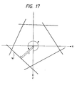
- Fig. 16 shows a plurality of reference planes, which are arranged to cover an object in an image processing apparatus according to the second embodiment.
- a reference plane a 161 is one of those arranged to surround the object.
- Fig. 17 is a top view of Fig. 16.
- ⁇ represents the angle the perpendicular dropped from the Y-axis to the reference plane a 161 makes with the Z-axis
- r represents the distance between the reference plane a 161 and the Y-axis.
- the distance between the Y-axis and the camera after rotation and translation is used as the distance from the Y-axis to the camera used upon calculating the line number.
- a point in a real space defines a linear path as in step S137.
- a line is drawn on the x-u space, and the colors of light rays present on this line are checked. If these light rays have similar colors, the line can be considered as the path of one point in the real space, and the average value of these colors is assigned to a position, where no light ray is present, on the line.
- This processing is performed while assuming every lines until the entire region on the x-u space are assigned with values (colors).
- the quality of an image generated can be improved as compared to a case wherein the color of a neighboring light ray is used.
- images taken at a plurality of viewpoint positions are input from the image input unit 11.
- images may be input from a memory medium such as a database, CD-ROM, or the like to the memory unit 14 via the memory medium reader 15.
- multi-viewpoint images are converted into light space data corresponding to a plurality of reference planes
- a region which cannot be expressed by a single reference plane can be expressed. Since a plurality of reference planes are used, the angle each reference plane makes with a light ray that passes through the plane becomes close to right angles. For this reason, the area of the x-u space corresponding to each reference plane can be small, and consequently, the data volume to be held can be reduced.
- Embodiments of the invention may comprise a system constituted by a plurality of devices or an apparatus consisting of a single device.
- An embodiment may also comprise a memory medium storing a program for the system or apparatus such that, by reading out the program from the memory medium to the system or apparatus, the system or apparatus operates in accordance with the predetermined method.
Claims (15)
- Appareil de traitement d'images comportant :un moyen (13, 14) de conversion de données d'images destiné à recevoir des données de pixels d'images pour plusieurs images d'entrée d'un objet prises dans des positions de points de vue différents en même temps que des données définissant les positions des points de vue et à convertir les données de pixels d'images en données de rayons lumineux définissant des rayons lumineux dans un espace à trois dimensions ;un moyen d'enregistrement (13, 14) destiné à enregistrer des données obtenues en projetant les rayons lumineux sur plusieurs plans de référence (141-144 ; 161), le moyen d'enregistrement étant agencé pour enregistrer les données pour chaque rayon lumineux respectif en projetant le rayon lumineux sur un plan de référence qui est sélectionné parmi les multiples plans de référence ;un moyen (12) à instruction de position de point de vue pour ordonner une position de point de vue ;un moyen de sélection (13, 14) destiné à sélectionner des données à partir des données enregistrées par ledit moyen d'enregistrement sur la base de la position de point de vue ordonnée par ledit moyen à instruction de position de point de vue ;un moyen (13, 14) de génération d'image destiné à générer des données d'image pour une image dans la position de point de vue ordonné par ledit moyen à instruction de position de point de vue sur la base des données sélectionnées par ledit moyen de sélection ; etun moyen de sortie (13, 14) destiné à délivrer en sortie les données d'image générées par ledit moyen de génération d'image vers un moyen d'affichage (17) pour l'affichage de l'image.
- Appareil selon la revendication 1, dans lequel ledit moyen (13, 14) de génération d'image peut être mis en oeuvre pour déterminer une ligne de balayage dans une image d'entrée conformément à la position de point de vue ordonnée par ledit moyen (12) à instruction de position de point de vue, et pour générer des données d'image pour l'image dans la position de point de vue ordonnée par ledit moyen à instruction de position de point de vue sur la base des données d'image sur la ligne de balayage déterminée.
- Appareil selon la revendication 1 ou la revendication 2, dans lequel ledit moyen (13, 14) de génération d'image peut être mis en oeuvre pour générer des données d'image pour une image stéréoscopique correspondant à la position de point de vue ordonnée par ledit moyen (12) à instruction de position de point de vue.
- Appareil selon l'une quelconque des revendications précédentes, dans lequel ledit moyen (12) à instruction de position de point de vue peut être mis en oeuvre pour déterminer la position de point de vue et une direction de ligne de visée d'un observateur.
- Appareil de traitement d'images comportant :un moyen (11, 15, 16) d'entrée d'images de points de vue multiples pour l'entrée de plusieurs images ayant différentes positions de points de vue en tant que données d'images de points de vue multiples ;un moyen (13, 14) de conversion d'images destiné à convertir les données d'images de points de vue multiples appliquées en entrée en rayons lumineux qui se déplacent dans un espace à trois dimensions ;un moyen (13, 14) d'enregistrement de rayons lumineux destiné à enregistrer les rayons lumineux convertis en tant que données d'espace de lumière en référence à plusieurs plans (141-144 ; 161) dans un espace à trois dimensions, le moyen d'enregistrement de rayons lumineux étant agencé pour enregistrer des données d'espace de lumière pour chaque rayon respectif en référence au plan, parmi les multiples plans de référence, qui forme un angle le plus proche d'un angle droit avec le rayon lumineux ;un moyen (12) d'entrée de position de point de vue et de direction de ligne de visée pour l'entrée d'une position de point de vue et d'une direction de ligne de visée d'une image devant être générée ;un moyen (13, 14) de calcul d'image destiné à générer des données d'image pour les pixels de l'image devant être générée en calculant des positions de ligne de balayage et de pixels pour l'image demandée et en déterminant des valeurs pour les pixels sur la base des données d'espace de lumière enregistrées.
- Appareil selon la revendication 5, dans lequel les multiples plans de référence (141-144) sont agencés radialement de façon que les plans de référence se croisent entre eux sur une première ligne passant par un objet, que des angles que des plans adjacents font soient égaux entre eux et que l'un des plans de référence fasse un angle égal à la moitié de l'angle que font des plans de référence adjacents avec une seconde ligne qui s'étend depuis la première ligne dans une direction d'une position de point de vue initiale et coupe perpendiculairement la première ligne.
- Appareil selon la revendication 6, dans lequel l'appareil peut être mis en oeuvre pour faire tourner des rayons lumineux passant par le plan de référence sur un angle de rotation à la suite d'une rotation du plan de référence pour se conformer à un plan qui contient la première ligne et qui croise perpendiculairement la seconde ligne et, dans cet état, pour enregistrer les rayons lumineux dans l'espace de lumière correspondant au plan de référence en utilisant les positions de passage des rayons lumineux tournés du plan croisant perpendiculairement la seconde ligne et les directions des rayons lumineux à ce moment.
- Appareil selon la revendication 5, dans lequel les multiples plans (161) sont agencés de façon à entourer au moins une partie d'un objet.
- Procédé de traitement d'images comprenant :une étape (S135) de conversion de données d'images destinée à recevoir des données de pixels d'images pour plusieurs images d'entrée d'un objet prises dans des positions de points de vue différentes en même temps que des données définissant les positions de points de vue et à convertir les données de pixels d'images en données de rayons lumineux définissant des rayons lumineux dans un espace à trois dimensions ;une étape d'enregistrement (S135, S136, S137) consistant à enregistrer des données obtenues en projetant les rayons lumineux sur plusieurs plans de référence (141-144 ; 161), les données pour chaque rayon lumineux respectif étant enregistrées en projetant le rayon lumineux sur un plan de référence qui est sélectionné parmi les multiples plans de référence ;une étape (S133, S134) de détermination de position de point de vue consistant à déterminer une position de point de vue ;une étape de sélection (S138) consistant à sélectionner des données à partir des données enregistrées dans l'étape d'enregistrement sur la base de la position de point de vue déterminée dans l'étape de détermination de position de point de vue ;une étape (S138) de génération d'image consistant à générer des données d'image pour une image dans la position de point de vue déterminée dans l'étape de détermination de position de point de vue sur la base des données sélectionnées dans l'étape de sélection ; etune étape de sortie (S138) consistant à délivrer en sortie les données d'image générées dans l'étape de génération d'image vers un moyen d'affichage pour afficher l'image.
- Procédé selon la revendication 9, dans lequel l'étape (S138) de génération d'image comprend l'étape consistant à déterminer une ligne de balayage dans une image d'entrée conformément à la position de point de vue déterminée dans l'étape de détermination de position de point de vue, et à générer des données d'image pour l'image dans la position de point de vue déterminée dans l'étape de détermination de position de point de vue sur la base des données d'image sur la ligne de balayage déterminée.
- Procédé selon la revendication 9 ou la revendication 10, dans lequel l'étape (S138) de génération d'image comprend l'étape consistant à générer des données d'image pour une image stéréoscopique correspondant à la position de point de vue déterminée dans l'étape de détermination de position de point de vue.
- Procédé de traitement d'images comprenant :l'étape (S135) d'entrée d'images de points de vue multiples consistant à entrer plusieurs images ayant différentes positions de points de vue en tant que données d'images de points de vue multiples ;l'étape (S135) de conversion d'image consistant à convertir les données d'image de points de vue multiples appliquées en entrée en rayons lumineux qui se déplacent dans un espace à trois dimensions ;l'étape (S135, S136, S137) d'enregistrement de rayons lumineux consistant à enregistrer les rayons lumineux convertis en tant que données d'espace de lumière en référence à plusieurs plans (141-144 ; 161) dans l'espace à trois dimensions de façon que les données d'espace de lumière pour chaque rayon respectif soient enregistrées en référence au plan, parmi les multiples plans de références, qui forme un angle le plus proche d'un angle droit avec le rayon lumineux ;l'étape (S133, S134) d'entrée de position de point de vue et de direction de ligne de visée consistant à l'application en entrée d'une position de point de vue et d'une direction de ligne de visée d'une image devant être générée ;l'étape (S138) de calcul d'image consistant à générer des données d'image pour les pixels de l'image devant être générée en calculant des positions de ligne de balayage et de pixels pour l'image demandée et en déterminant des valeurs pour les pixels sur la base des données d'espace de lumière enregistrées.
- Procédé selon la revendication 12, dans lequel les multiples plans de référence (141-144) sont agencés radialement de manière que les plans de référence se croisent mutuellement sur une première ligne passant par un objet, que les angles que des plans adjacents font soient égaux entre eux et que l'un des plans de référence fasse un angle égal à la moitié de l'angle que des plans de référence adjacents font avec une seconde ligne qui s'étend depuis la première ligne dans une direction d'une position de point de vue initiale et coupe perpendiculairement la première ligne.
- Procédé selon la revendication 13, dans lequel les rayons lumineux passant par le plan de référence sont tournés d'un angle de rotation sous l'effet d'une rotation du plan de référence pour se conformer à un plan qui contient la première ligne et qui croise perpendicuairement la seconde ligne et, dans cet état, les rayons lumineux sont enregistrés dans l'espace de lumière correspondant au plan de référence en utilisant les positions de passage des rayons lumineux tournés du plan croisant perpendiculairement la seconde ligne et les directions des rayons lumineux à ce moment.
- Produit à programme d'ordinateur, comportant un support portant des instructions pour la programmation d'un appareil de traitement programmable afin qu'il puisse devenir apte à exécuter un procédé tel que défini dans au moins l'une des revendications 9 à 14.
Applications Claiming Priority (6)
| Application Number | Priority Date | Filing Date | Title |
|---|---|---|---|
| JP6624596 | 1996-03-22 | ||
| JP6624596A JPH09261537A (ja) | 1996-03-22 | 1996-03-22 | 画像処理装置及び画像処理方法 |
| JP66245/96 | 1996-03-22 | ||
| JP179078/96 | 1996-07-09 | ||
| JP17907896A JPH1027264A (ja) | 1996-07-09 | 1996-07-09 | 画像処理装置及び画像処理方法 |
| JP17907896 | 1996-07-09 |
Publications (3)
| Publication Number | Publication Date |
|---|---|
| EP0797171A2 EP0797171A2 (fr) | 1997-09-24 |
| EP0797171A3 EP0797171A3 (fr) | 1998-10-07 |
| EP0797171B1 true EP0797171B1 (fr) | 2005-11-30 |
Family
ID=26407416
Family Applications (1)
| Application Number | Title | Priority Date | Filing Date |
|---|---|---|---|
| EP97301798A Expired - Lifetime EP0797171B1 (fr) | 1996-03-22 | 1997-03-18 | Méthode et appareil de traitement d'image |
Country Status (3)
| Country | Link |
|---|---|
| US (1) | US6445807B1 (fr) |
| EP (1) | EP0797171B1 (fr) |
| DE (1) | DE69734747T2 (fr) |
Families Citing this family (27)
| Publication number | Priority date | Publication date | Assignee | Title |
|---|---|---|---|---|
| US6704042B2 (en) * | 1998-12-10 | 2004-03-09 | Canon Kabushiki Kaisha | Video processing apparatus, control method therefor, and storage medium |
| US6906708B1 (en) * | 1999-03-26 | 2005-06-14 | Canon Kabushiki Kaisha | Image processing method and apparatus, and storage medium |
| US6674922B1 (en) * | 1999-03-26 | 2004-01-06 | Canon Kabushiki Kaisha | Image processing method, image processing apparatus, and storage medium |
| JP2001008232A (ja) * | 1999-06-25 | 2001-01-12 | Matsushita Electric Ind Co Ltd | 全方位映像出力方法と装置 |
| US7035453B2 (en) * | 2000-03-24 | 2006-04-25 | Reality Commerce Corporation | Method and apparatus for parallel multi-view point video capturing and compression |
| US20030052899A1 (en) * | 2000-08-16 | 2003-03-20 | Diana Walczak | Dynamic spatial warp |
| US6999080B1 (en) * | 2000-11-30 | 2006-02-14 | Microsoft Corporation | System, method, and computer program product for general environment mapping |
| TW492558U (en) * | 2001-01-18 | 2002-06-21 | Chitai Technology Co Ltd | Passive three-dimensional taking picture control apparatus |
| JP4211292B2 (ja) * | 2002-06-03 | 2009-01-21 | ソニー株式会社 | 画像処理装置および画像処理方法、プログラム並びにプログラム記録媒体 |
| JP4115188B2 (ja) * | 2002-07-19 | 2008-07-09 | キヤノン株式会社 | 仮想空間描画表示装置 |
| US20040222987A1 (en) * | 2003-05-08 | 2004-11-11 | Chang Nelson Liang An | Multiframe image processing |
| JP2005050037A (ja) * | 2003-07-31 | 2005-02-24 | Canon Inc | 画像処理方法および装置 |
| JP4262013B2 (ja) * | 2003-07-31 | 2009-05-13 | キヤノン株式会社 | 画像処理方法および画像生成装置 |
| JP3879732B2 (ja) * | 2003-11-27 | 2007-02-14 | コニカミノルタホールディングス株式会社 | 物体検出装置、物体検知方法、およびコンピュータプログラム |
| US7542050B2 (en) * | 2004-03-03 | 2009-06-02 | Virtual Iris Studios, Inc. | System for delivering and enabling interactivity with images |
| US7502036B2 (en) * | 2004-03-03 | 2009-03-10 | Virtual Iris Studios, Inc. | System for delivering and enabling interactivity with images |
| BRPI0507131A2 (pt) * | 2004-03-03 | 2011-05-17 | Virtual Iris Studios Inc | sistema para entrega e habilitação de interatividade com imagens |
| JP3935499B2 (ja) * | 2004-07-26 | 2007-06-20 | 松下電器産業株式会社 | 画像処理方法、画像処理装置および画像処理プログラム |
| JP4481280B2 (ja) * | 2006-08-30 | 2010-06-16 | 富士フイルム株式会社 | 画像処理装置、及び画像処理方法 |
| WO2009013744A2 (fr) * | 2007-07-23 | 2009-01-29 | Humaneyes Technologies Ltd. | Dddispositifs d'affichage à vues multiples et leurs procédés de fabrication |
| US20090087013A1 (en) * | 2007-09-28 | 2009-04-02 | Zoom Information Systems (The Mainz Group Ll) | Ray mapping |
| JP5249114B2 (ja) * | 2009-04-03 | 2013-07-31 | Kddi株式会社 | 画像生成装置、方法及びプログラム |
| US20110001791A1 (en) * | 2009-07-02 | 2011-01-06 | Emaze Imaging Techonolgies Ltd. | Method and system for generating and displaying a three-dimensional model of physical objects |
| US8704879B1 (en) | 2010-08-31 | 2014-04-22 | Nintendo Co., Ltd. | Eye tracking enabling 3D viewing on conventional 2D display |
| KR101763938B1 (ko) * | 2010-11-03 | 2017-08-01 | 삼성전자주식회사 | 위치정보 기반의 영상데이터의 처리 방법 및 장치 |
| KR102608466B1 (ko) * | 2016-11-22 | 2023-12-01 | 삼성전자주식회사 | 영상 처리 방법 및 영상 처리 장치 |
| CN113079364A (zh) * | 2021-03-24 | 2021-07-06 | 纵深视觉科技(南京)有限责任公司 | 一种静态对象的立体显示方法、装置、介质及电子设备 |
Family Cites Families (10)
| Publication number | Priority date | Publication date | Assignee | Title |
|---|---|---|---|---|
| JPH0769972B2 (ja) * | 1987-07-16 | 1995-07-31 | インタ−ナショナル・ビジネス・マシ−ンズ・コ−ポレ−ション | 画像生成方法 |
| US5073819A (en) * | 1990-04-05 | 1991-12-17 | Computer Scaled Video Surveys, Inc. | Computer assisted video surveying and method thereof |
| CA2040273C (fr) * | 1990-04-13 | 1995-07-18 | Kazu Horiuchi | Systeme d'affichage d'images |
| US5613048A (en) * | 1993-08-03 | 1997-03-18 | Apple Computer, Inc. | Three-dimensional image synthesis using view interpolation |
| US5420788A (en) * | 1993-08-09 | 1995-05-30 | General Electric Company | Method for processing data in 2D and 3D computed X-ray tomography |
| JPH0877356A (ja) * | 1994-09-09 | 1996-03-22 | Fujitsu Ltd | 三次元多眼画像の処理方法及び処理装置 |
| GB9424273D0 (en) * | 1994-12-01 | 1995-01-18 | Wrigley Adrian M T | Improvements in and relating to image constrcution |
| US5703961A (en) * | 1994-12-29 | 1997-12-30 | Worldscape L.L.C. | Image transformation and synthesis methods |
| US5796386A (en) * | 1995-01-23 | 1998-08-18 | International Business Machines Corporation | Precise calibration procedure for sensor-based view point control system |
| US6009188A (en) * | 1996-02-16 | 1999-12-28 | Microsoft Corporation | Method and system for digital plenoptic imaging |
-
1997
- 1997-03-18 DE DE69734747T patent/DE69734747T2/de not_active Expired - Lifetime
- 1997-03-18 US US08/819,093 patent/US6445807B1/en not_active Expired - Lifetime
- 1997-03-18 EP EP97301798A patent/EP0797171B1/fr not_active Expired - Lifetime
Non-Patent Citations (1)
| Title |
|---|
| CHEN S E: "QuickTime VR-an image-based approach to virtual environment navigation", PROCEEDINGS OF SIGGRAPH 1995, 6 August 1995 (1995-08-06) - 11 August 1995 (1995-08-11), Los Angeles, CA, USA, pages 29 - 38 * |
Also Published As
| Publication number | Publication date |
|---|---|
| EP0797171A3 (fr) | 1998-10-07 |
| US6445807B1 (en) | 2002-09-03 |
| DE69734747D1 (de) | 2006-01-05 |
| DE69734747T2 (de) | 2006-07-27 |
| EP0797171A2 (fr) | 1997-09-24 |
Similar Documents
| Publication | Publication Date | Title |
|---|---|---|
| EP0797171B1 (fr) | Méthode et appareil de traitement d'image | |
| US6191808B1 (en) | Image processing method with viewpoint compensation and apparatus therefor | |
| JP4947593B2 (ja) | 局所領域分割による自由視点画像の生成装置およびプログラム | |
| KR100967826B1 (ko) | 화상처리장치 및 방법, 프로그램 및 프로그램 기록매체,및 데이터구조 및 데이터 기록매체 | |
| US6791598B1 (en) | Methods and apparatus for information capture and steroscopic display of panoramic images | |
| JP2874710B2 (ja) | 三次元位置計測装置 | |
| Luo et al. | Parallax360: Stereoscopic 360 scene representation for head-motion parallax | |
| JP4065488B2 (ja) | 3次元画像生成装置、3次元画像生成方法及び記憶媒体 | |
| US20020164067A1 (en) | Nearest neighbor edge selection from feature tracking | |
| US6486877B1 (en) | Method and apparatus for creating virtual environment, and record medium having recorded thereon computer readable program for creating virtual environment | |
| WO2000036564A9 (fr) | Creation de modele tridimensionnel a partir d'images bidimensionnelles | |
| JP6683307B2 (ja) | 多数のカメラを用いた最適の球形映像獲得方法 | |
| Lin et al. | On the number of samples needed in light field rendering with constant-depth assumption | |
| US20120154548A1 (en) | Left/right image generation for 360-degree stereoscopic video | |
| WO2009093136A2 (fr) | Capture d'image et génération de film cinématographique | |
| US20120154519A1 (en) | Chassis assembly for 360-degree stereoscopic video capture | |
| US6795090B2 (en) | Method and system for panoramic image morphing | |
| Smith et al. | Cultural heritage omni-stereo panoramas for immersive cultural analytics—from the Nile to the Hijaz | |
| WO2008034942A1 (fr) | Procédé et appareil de formation d'images stéréoscopiques panoramiques | |
| US6256035B1 (en) | Image processing method and apparatus | |
| JP4778569B2 (ja) | ステレオ画像処理装置、ステレオ画像処理方法及びステレオ画像処理プログラム | |
| JP2004258775A (ja) | 光線空間データ処理方法、空間データ処理装置 | |
| JPH09138850A (ja) | 表面形状再構成装置 | |
| JPH09237346A (ja) | 部分立体モデルの合成方法及び完全立体モデルの作成方法 | |
| Maimone et al. | A taxonomy for stereo computer vision experiments |
Legal Events
| Date | Code | Title | Description |
|---|---|---|---|
| PUAI | Public reference made under article 153(3) epc to a published international application that has entered the european phase |
Free format text: ORIGINAL CODE: 0009012 |
|
| AK | Designated contracting states |
Kind code of ref document: A2 Designated state(s): DE FR GB IT NL |
|
| PUAL | Search report despatched |
Free format text: ORIGINAL CODE: 0009013 |
|
| AK | Designated contracting states |
Kind code of ref document: A3 Designated state(s): DE FR GB IT NL |
|
| 17P | Request for examination filed |
Effective date: 19990222 |
|
| 17Q | First examination report despatched |
Effective date: 20010628 |
|
| GRAP | Despatch of communication of intention to grant a patent |
Free format text: ORIGINAL CODE: EPIDOSNIGR1 |
|
| GRAS | Grant fee paid |
Free format text: ORIGINAL CODE: EPIDOSNIGR3 |
|
| GRAA | (expected) grant |
Free format text: ORIGINAL CODE: 0009210 |
|
| AK | Designated contracting states |
Kind code of ref document: B1 Designated state(s): DE FR GB IT NL |
|
| PG25 | Lapsed in a contracting state [announced via postgrant information from national office to epo] |
Ref country code: NL Free format text: LAPSE BECAUSE OF FAILURE TO SUBMIT A TRANSLATION OF THE DESCRIPTION OR TO PAY THE FEE WITHIN THE PRESCRIBED TIME-LIMIT Effective date: 20051130 Ref country code: IT Free format text: LAPSE BECAUSE OF FAILURE TO SUBMIT A TRANSLATION OF THE DESCRIPTION OR TO PAY THE FEE WITHIN THE PRESCRIBED TIME-LIMIT;WARNING: LAPSES OF ITALIAN PATENTS WITH EFFECTIVE DATE BEFORE 2007 MAY HAVE OCCURRED AT ANY TIME BEFORE 2007. THE CORRECT EFFECTIVE DATE MAY BE DIFFERENT FROM THE ONE RECORDED. Effective date: 20051130 |
|
| REG | Reference to a national code |
Ref country code: GB Ref legal event code: FG4D |
|
| REF | Corresponds to: |
Ref document number: 69734747 Country of ref document: DE Date of ref document: 20060105 Kind code of ref document: P |
|
| NLV1 | Nl: lapsed or annulled due to failure to fulfill the requirements of art. 29p and 29m of the patents act | ||
| ET | Fr: translation filed | ||
| PLBE | No opposition filed within time limit |
Free format text: ORIGINAL CODE: 0009261 |
|
| STAA | Information on the status of an ep patent application or granted ep patent |
Free format text: STATUS: NO OPPOSITION FILED WITHIN TIME LIMIT |
|
| 26N | No opposition filed |
Effective date: 20060831 |
|
| PGFP | Annual fee paid to national office [announced via postgrant information from national office to epo] |
Ref country code: DE Payment date: 20140331 Year of fee payment: 18 |
|
| PGFP | Annual fee paid to national office [announced via postgrant information from national office to epo] |
Ref country code: GB Payment date: 20140318 Year of fee payment: 18 |
|
| PGFP | Annual fee paid to national office [announced via postgrant information from national office to epo] |
Ref country code: FR Payment date: 20140326 Year of fee payment: 18 |
|
| REG | Reference to a national code |
Ref country code: DE Ref legal event code: R119 Ref document number: 69734747 Country of ref document: DE |
|
| GBPC | Gb: european patent ceased through non-payment of renewal fee |
Effective date: 20150318 |
|
| REG | Reference to a national code |
Ref country code: FR Ref legal event code: ST Effective date: 20151130 |
|
| PG25 | Lapsed in a contracting state [announced via postgrant information from national office to epo] |
Ref country code: GB Free format text: LAPSE BECAUSE OF NON-PAYMENT OF DUE FEES Effective date: 20150318 Ref country code: DE Free format text: LAPSE BECAUSE OF NON-PAYMENT OF DUE FEES Effective date: 20151001 |
|
| PG25 | Lapsed in a contracting state [announced via postgrant information from national office to epo] |
Ref country code: FR Free format text: LAPSE BECAUSE OF NON-PAYMENT OF DUE FEES Effective date: 20150331 |