EP0797086B1 - Système d'équilibrage d'un pneu de véhicule - Google Patents
Système d'équilibrage d'un pneu de véhicule Download PDFInfo
- Publication number
- EP0797086B1 EP0797086B1 EP97104749A EP97104749A EP0797086B1 EP 0797086 B1 EP0797086 B1 EP 0797086B1 EP 97104749 A EP97104749 A EP 97104749A EP 97104749 A EP97104749 A EP 97104749A EP 0797086 B1 EP0797086 B1 EP 0797086B1
- Authority
- EP
- European Patent Office
- Prior art keywords
- wheel
- vehicle wheel
- balancing
- weights
- motor vehicle
- Prior art date
- Legal status (The legal status is an assumption and is not a legal conclusion. Google has not performed a legal analysis and makes no representation as to the accuracy of the status listed.)
- Expired - Lifetime
Links
- 239000000853 adhesive Substances 0.000 description 11
- 230000001070 adhesive effect Effects 0.000 description 11
- 238000000034 method Methods 0.000 description 2
- 238000004026 adhesive bonding Methods 0.000 description 1
- 238000010276 construction Methods 0.000 description 1
- 230000000007 visual effect Effects 0.000 description 1
Images

Classifications
-
- G—PHYSICS
- G01—MEASURING; TESTING
- G01M—TESTING STATIC OR DYNAMIC BALANCE OF MACHINES OR STRUCTURES; TESTING OF STRUCTURES OR APPARATUS, NOT OTHERWISE PROVIDED FOR
- G01M1/00—Testing static or dynamic balance of machines or structures
- G01M1/30—Compensating imbalance
- G01M1/32—Compensating imbalance by adding material to the body to be tested, e.g. by correcting-weights
- G01M1/326—Compensating imbalance by adding material to the body to be tested, e.g. by correcting-weights the body being a vehicle wheel
Definitions
- the invention relates to a system for "industrial balancing" in particular larger Series of motor vehicle wheels, which detects an imbalance in two levels of the wheel and by attaching at least one balance weight in each of the two planes is compensated, consisting of at least one balancing machine for the determination and Marking the imbalance and a device with a holder which is connected to the balancing machine via a conveyor line and in the respective motor vehicle wheel after determination and marking of the imbalances to Attach a balance weight in a vertical position is positionable.
- the invention further relates to a method for balancing a Motor vehicle wheel.
- Such systems for industrial balancing of motor vehicle wheels are e.g. out the German patent DE1084494, long known and exist usually from a balancing machine for determining and marking the imbalances and a device with a holder in which the motor vehicle wheel for fastening is positioned by balancing weights in a vertical position, wherein the Balancing machine and the device be connected to each other by a conveyor line can.
- the device for fixing the Balance weights designed differently.
- German Offenlegungsschrift DE-OS2321437 discloses a device for Balancing of imbalance bodies, in particular vehicle wheels known. These Device comprises a rotatable clamping shaft, which at several bearing points, on which transducers are provided on. The imbalance is in one vertical position of the clamping shaft determined in two balancing planes and balanced. The clamping shaft is between a horizontal and a vertical Position designed swiveling. The horizontal position of the clamping shaft becomes the used simple and safe clamping of the wheel. It will be exclusively Impact weights to compensate for the respective imbalance in the horizontal position used.
- European patent application EP0557240A2 describes a device for the Balancing wheels, which one from a horizontal to a vertical position having pivotable receiving axis.
- the receiving axle is for attachment and brought to release the respective wheels in the horizontal position.
- the measuring process for the determination and Marking the imbalance of the wheel made.
- US Pat. No. 2,201,982 discloses an assembly / disassembly and a Imbalance compensation device for wheels.
- the assembly / disassembly and the Determination and marking of the imbalance of the respective wheels is in the horizontal position of the receiving axis of the device and the axis of rotation of the Rades performed.
- the invention has for its object to provide a system for balancing a Vehicle wheel to create, with the in a particularly simple way also Vehicle wheels can be balanced, in which all marketable Balance weights should be sorted or used in any combination.
- the characterizing features of claim 1 is in a system of The aforementioned type, the object achieved in that the holder of the device can be pivoted by 90 °, so that the motor vehicle wheel located in the holder for Fixing a balance weight of able also in a horizontal position is pivotable.
- the basic idea of the invention lies in the fact that the motor vehicle wheel after the Determining the imbalance in a balancing machine is supplied to a device, in the motor vehicle wheel can be positioned both vertically and horizontally, both Positionings are "equal". Thus one becomes independent of the used balancing weights.
- the inventive system is particularly versatile and balancing weights of any kind both individually as well as in any combination with each other are usable.
- Another advantage the invention is to be seen in that the device for fixing the Compensating two devices combined and thus much more compact is as a "series connection" of the two devices, so that the entire System occupies little space. Due to the compact construction of the device it is possible that the operator during the attachment of the balance weights always the same working position can take. Finally, existing devices mostly converted in a simple manner to the device according to the invention become.
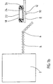
- Fig. 1 shows a schematic representation of a system for balancing a Motor vehicle wheel from the side, consisting of a balancing machine 2, a Conveyor 4 and a known wheel well B in the balancing machine 2 are the imbalances of a motor vehicle wheel measured in two planes and those bodies marked on the vehicle wheel on which balance weights are to be attached.
- balancing machines 2 are known from the prior art, so that they are here will not be described in detail.
- the motor vehicle wheel 14 is placed on a conveyor line 4, the wheel outer surface 20 of the motor vehicle wheel 14 points away from the conveyor track 4 (See Figure la, note that the motor vehicle wheel 14 is shown in cross-section).
- the motor vehicle wheel 14 By driving the conveyor rollers 6, the motor vehicle wheel 14 in the direction of Wheel well 8 transported.
- the vehicle wheel 14 falls into the wheel well 8, that it assumes a vertical position in the holder 12 of the wheel well 8, wherein the Radaull Structure 20 of the vehicle wheel 14 facing away from the balancing machine 2.
- This vertical position is, for example, a first by an operator Balance weight in the first plane formed by the wheel outer surface 20, between the tire 16 and the rim 18 of the vehicle wheel 14 taken or stapled.
- Fig. 1a it can be seen that an operator, the outer wheel surface 20 and the Wheel inner surface 22 in the vertical position of the vehicle wheel 14 for mounting of balancing weights is particularly well accessible (in particular is a wrapping very precise and fast possible.) Often, however, it is provided, at least one adhesive weight in the rim bowl 24 of the rim 18 of the Vehicle wheel 14 to install, ie in a plane that between the outer wheel surface 20 and the inner wheel surface 22 and thus in the "interior" of the Vehicle wheel 14 is located. This plane is shown in the vertical position of FIG Vehicle wheel 14 difficult to access and accurate positioning of Adhesive weights is virtually impossible (also note here that the motor vehicle wheel 14 is shown in cross-section and therefore Fig. 1a is deceiving; in reality he sees Operator only the tire 16 in front of him and could only from the left side without view in the Grab rim bowl 24 to position an adhesive weight there).
- the holder 12 of the wheel well 8 about the axis 10 - preferably by a mechanical drive - pivoted by 90 ', so that the Holder 12 of the wheel well 8 assumes the position shown in FIG. 1b and the Vehicle wheel 14 is transferred to a horizontal position, wherein the Radinnen Chemistry 22nd pointing away from the wheel well 8.
- the Radinnen Chemistry 22nd pointing away from the wheel well 8.
- this horizontal position is the Rim bowl 24 of the rim 18 of the vehicle wheel 14 visible to an operator and accessible so that an adhesive weight in an exact position in the rim 24th can be attached.
- the vehicle wheel 14 After attachment of the balance weights on the motor vehicle wheel 14 in the wheel well 8 the vehicle wheel 14 is pivoted back into the trough and then into known way from the wheel well 8 "ejected" and further processed.
Landscapes
- Physics & Mathematics (AREA)
- General Physics & Mathematics (AREA)
- Testing Of Balance (AREA)
Claims (1)
- Système d'équilibrage industriel notamment pour grandes séries de roues de véhicules automobiles, dans lesquelles un déséquilibre dans deux plans est détecté et est compensé par la fixation d'au moins un poids d'équilibrage dans chacun des deux plans, se composant d'au moins une machine d'équilibrage pour détecter et marquer le déséquilibre et d'un dispositif comprenant un support, qui est connecté à la machine d'équilibrage par le biais d'une ligne de transport et dans lequel la roue de véhicule automobile respective, après la détection et le marquage du déséquilibre, peut être positionnée dans une position verticale pour la fixation d'un poids d'équilibrage, le support (12) du dispositif (8) pouvant pivoter de 90° de sorte que la roue du véhicule automobile (14) se trouvant dans le support (12) puisse être aussi pivotée de la position verticale dans une position horizontale pour la fixation d'un autre poids d'équilibrage.
Applications Claiming Priority (2)
| Application Number | Priority Date | Filing Date | Title |
|---|---|---|---|
| DE19611574A DE19611574C1 (de) | 1996-03-23 | 1996-03-23 | System zum industriellen Auswuchten insbesondere größerer Serien von Kraftfahrzeugrädern |
| DE19611574 | 1996-03-23 |
Publications (3)
| Publication Number | Publication Date |
|---|---|
| EP0797086A2 EP0797086A2 (fr) | 1997-09-24 |
| EP0797086A3 EP0797086A3 (fr) | 1998-12-09 |
| EP0797086B1 true EP0797086B1 (fr) | 2005-11-02 |
Family
ID=7789236
Family Applications (1)
| Application Number | Title | Priority Date | Filing Date |
|---|---|---|---|
| EP97104749A Expired - Lifetime EP0797086B1 (fr) | 1996-03-23 | 1997-03-20 | Système d'équilibrage d'un pneu de véhicule |
Country Status (3)
| Country | Link |
|---|---|
| EP (1) | EP0797086B1 (fr) |
| AT (1) | ATE308742T1 (fr) |
| DE (2) | DE19611574C1 (fr) |
Families Citing this family (8)
| Publication number | Priority date | Publication date | Assignee | Title |
|---|---|---|---|---|
| DE19927307C2 (de) * | 1999-06-15 | 2001-05-17 | Haweka Gmbh | Auswuchtvorrichtung |
| DE19961828B4 (de) * | 1999-12-21 | 2004-12-16 | Hofmann Maschinen- Und Anlagenbau Gmbh | Verfahren zum Anbringen von Unwuchtausgleichsgewichten an einem Fahrzeugrad und Vorrichtung zur Durchführung des Verfahrens |
| DE10000683A1 (de) * | 2000-01-10 | 2001-07-12 | Schenck Rotec Gmbh | Vorrichtung zum Auswuchten eines Fahrzeugrades |
| DE10245519A1 (de) | 2002-09-27 | 2004-04-08 | Schenck Rotec Gmbh | Unwuchtausgleichsstation für Fahrzeugräder |
| US20050229702A1 (en) * | 2004-04-14 | 2005-10-20 | Illinois Tool Works, Inc. | Tire weight applying apparatus |
| US7448267B2 (en) | 2004-04-14 | 2008-11-11 | Micro-Poise Measurement Systems, Llc | Tire balancing apparatus |
| CN100559140C (zh) * | 2004-04-14 | 2009-11-11 | 伊利诺斯器械工程公司 | 配重施加设备 |
| DE102007024753B4 (de) * | 2007-05-26 | 2009-05-07 | Bayerische Motoren Werke Aktiengesellschaft | Verfahren zum Prüfen fehlerhaft montierter Fahrzeugreifen |
Family Cites Families (4)
| Publication number | Priority date | Publication date | Assignee | Title |
|---|---|---|---|---|
| US2201982A (en) * | 1935-07-13 | 1940-05-28 | Wintercorn Andrew F | Combination tire changer and wheel balancer and tool therefor |
| DE1698628B2 (de) * | 1968-02-21 | 1973-02-08 | Maschinenfabrik Dionys Hofmann Gmbh, 7477 Onstmettingen | Vorrichtung zum automatischen auswuchten von kraftfahrzeugraedern in zwei ausgleichsebenen |
| ES2113516T3 (es) * | 1992-02-20 | 1998-05-01 | Interbalco Ag | Aparato para el equilibrado de ruedas. |
| DE4229865C2 (de) * | 1992-09-07 | 1994-12-22 | Hofmann Werkstatt Technik | Verfahren zum Ausgleichen der Unwucht eines Kraftfahrzeugrades und Vorrichtung zur Durchführung des Verfahrens |
-
1996
- 1996-03-23 DE DE19611574A patent/DE19611574C1/de not_active Expired - Fee Related
-
1997
- 1997-03-20 EP EP97104749A patent/EP0797086B1/fr not_active Expired - Lifetime
- 1997-03-20 DE DE59712463T patent/DE59712463D1/de not_active Expired - Lifetime
- 1997-03-20 AT AT97104749T patent/ATE308742T1/de not_active IP Right Cessation
Also Published As
| Publication number | Publication date |
|---|---|
| EP0797086A3 (fr) | 1998-12-09 |
| DE19611574C1 (de) | 1997-05-07 |
| EP0797086A2 (fr) | 1997-09-24 |
| ATE308742T1 (de) | 2005-11-15 |
| DE59712463D1 (de) | 2005-12-08 |
Similar Documents
| Publication | Publication Date | Title |
|---|---|---|
| EP0247350B1 (fr) | Procédé et dispositif pour optimiser l'équilibrage d'une roue de véhicule | |
| DE4143624C2 (de) | Auswuchtmaschine für Kraftfahrzeugräder | |
| DE3115609A1 (de) | Verfahren und vorrichtung zum kennzeichnen von unwuchten an einem rotationskoerper, insbesondere kraftfahrzeugrad" | |
| DE60204315T2 (de) | Verfahren und Vorrichtung zur Bestimmung der geometrischen Daten eines auf einer Welle drehbar montierten Kraftfahrzeugrades | |
| DE4415931C2 (de) | Verfahren zum Ausgleich einer Unwucht an einem Kraftfahrzeugrad und Vorrichtung zur Durchführung des Verfahrens | |
| EP0797086B1 (fr) | Système d'équilibrage d'un pneu de véhicule | |
| DE4240787A1 (de) | Verfahren und Vorrichtung zum dynamischen Auswuchten eines Rotors | |
| EP0650042B1 (fr) | Procédé et dispositif de maintien en position d'une roue de véhicule serrée sur un axe de mesure d'une machine d'équilibrage | |
| DE10035340A1 (de) | Verfahren und Vorrichtung zum dynamischen Auswuchten einer Welle | |
| DE10316767A1 (de) | Unwuchtmeßeinrichtung und Verfahren zur Unwuchtmessung | |
| DE102004004299A1 (de) | Bildgebendes Tomographie-Gerät | |
| DE69415494T2 (de) | Verfahren und vorrichtung für die verwendung von messmethoden zur bestimmung der rollreibung und des haftungsgrenzwertes | |
| DE102004004298B4 (de) | Verfahren zur Kompensation einer Unwucht bei einem bildgebenden Tomographie-Gerät | |
| EP0278037B1 (fr) | Machine pour centrer l'équilibrage de corps en rotation | |
| DE69413622T2 (de) | Verfahren zur Unwuchtkorrektur von einem auf einer Felge montierten Reifen | |
| DE102017117035A1 (de) | Prüfrad zur Verwendung in einer Reifenprüfmaschine | |
| DE102022207743A1 (de) | Unwuchtmesseinrichtung, Bearbeitungseinrichtung, sowie Verfahren zur Bearbeitung eines Werkstücks | |
| DE69108437T2 (de) | An einer Felge montierter Reifen und Verfahren zur Unwuchtkorrektur. | |
| DE3714470A1 (de) | Verfahren und einrichtung zum ueberwachen von schwingungserregern in fahrwerkkomponenten bei kraftfahrzeugen waehrend des fahrbetriebs | |
| DE102004004300B4 (de) | Bildgebendes Tomographie-Gerät mit Auswuchtvorrichtung | |
| DE2701876A1 (de) | Vorrichtung zum auswuchten von rotoren, insbesondere fahrzeugraedern | |
| DE102004004301B4 (de) | Bildgebendes Tomographie-Gerät mit Ausgleichsringen zur Kompensation einer Unwucht | |
| DE10105939A1 (de) | Verfahren und Vorrichtung zum Kalibrieren einer Unwuchtmesseinrichtung | |
| EP1519177B1 (fr) | Procédé de calibrage un appareil d'equilibrage des pneus et machine d'équilibrage de pneus | |
| DE102007063025A1 (de) | Verfahren und Vorrichtung zur optimierten Fertigung von Fahrzeugrädern |
Legal Events
| Date | Code | Title | Description |
|---|---|---|---|
| PUAI | Public reference made under article 153(3) epc to a published international application that has entered the european phase |
Free format text: ORIGINAL CODE: 0009012 |
|
| AK | Designated contracting states |
Kind code of ref document: A2 Designated state(s): AT BE CH DE DK ES FR GB IE IT LI LU NL PT SE |
|
| PUAL | Search report despatched |
Free format text: ORIGINAL CODE: 0009013 |
|
| AK | Designated contracting states |
Kind code of ref document: A3 Designated state(s): AT BE CH DE DK ES FR GB IE IT LI LU NL PT SE |
|
| 17P | Request for examination filed |
Effective date: 19990609 |
|
| 17Q | First examination report despatched |
Effective date: 20030317 |
|
| APBN | Date of receipt of notice of appeal recorded |
Free format text: ORIGINAL CODE: EPIDOSNNOA2E |
|
| APBR | Date of receipt of statement of grounds of appeal recorded |
Free format text: ORIGINAL CODE: EPIDOSNNOA3E |
|
| APBV | Interlocutory revision of appeal recorded |
Free format text: ORIGINAL CODE: EPIDOSNIRAPE |
|
| GRAP | Despatch of communication of intention to grant a patent |
Free format text: ORIGINAL CODE: EPIDOSNIGR1 |
|
| GRAS | Grant fee paid |
Free format text: ORIGINAL CODE: EPIDOSNIGR3 |
|
| GRAA | (expected) grant |
Free format text: ORIGINAL CODE: 0009210 |
|
| AK | Designated contracting states |
Kind code of ref document: B1 Designated state(s): AT BE CH DE DK ES FR GB IE IT LI LU NL PT SE |
|
| PG25 | Lapsed in a contracting state [announced via postgrant information from national office to epo] |
Ref country code: NL Free format text: LAPSE BECAUSE OF FAILURE TO SUBMIT A TRANSLATION OF THE DESCRIPTION OR TO PAY THE FEE WITHIN THE PRESCRIBED TIME-LIMIT Effective date: 20051102 Ref country code: IT Free format text: LAPSE BECAUSE OF FAILURE TO SUBMIT A TRANSLATION OF THE DESCRIPTION OR TO PAY THE FEE WITHIN THE PRE;WARNING: LAPSES OF ITALIAN PATENTS WITH EFFECTIVE DATE BEFORE 2007 MAY HAVE OCCURRED AT ANY TIME BEFORE 2007. THE CORRECT EFFECTIVE DATE MAY BE DIFFERENT FROM THE ONE RECORDED.SCRIBED TIME-LIMIT Effective date: 20051102 Ref country code: IE Free format text: LAPSE BECAUSE OF FAILURE TO SUBMIT A TRANSLATION OF THE DESCRIPTION OR TO PAY THE FEE WITHIN THE PRESCRIBED TIME-LIMIT Effective date: 20051102 Ref country code: GB Free format text: LAPSE BECAUSE OF FAILURE TO SUBMIT A TRANSLATION OF THE DESCRIPTION OR TO PAY THE FEE WITHIN THE PRESCRIBED TIME-LIMIT Effective date: 20051102 |
|
| REG | Reference to a national code |
Ref country code: GB Ref legal event code: FG4D Free format text: NOT ENGLISH |
|
| REG | Reference to a national code |
Ref country code: CH Ref legal event code: EP |
|
| REF | Corresponds to: |
Ref document number: 59712463 Country of ref document: DE Date of ref document: 20051208 Kind code of ref document: P |
|
| PG25 | Lapsed in a contracting state [announced via postgrant information from national office to epo] |
Ref country code: SE Free format text: LAPSE BECAUSE OF FAILURE TO SUBMIT A TRANSLATION OF THE DESCRIPTION OR TO PAY THE FEE WITHIN THE PRESCRIBED TIME-LIMIT Effective date: 20060202 Ref country code: DK Free format text: LAPSE BECAUSE OF FAILURE TO SUBMIT A TRANSLATION OF THE DESCRIPTION OR TO PAY THE FEE WITHIN THE PRESCRIBED TIME-LIMIT Effective date: 20060202 |
|
| PG25 | Lapsed in a contracting state [announced via postgrant information from national office to epo] |
Ref country code: ES Free format text: LAPSE BECAUSE OF FAILURE TO SUBMIT A TRANSLATION OF THE DESCRIPTION OR TO PAY THE FEE WITHIN THE PRESCRIBED TIME-LIMIT Effective date: 20060213 |
|
| PG25 | Lapsed in a contracting state [announced via postgrant information from national office to epo] |
Ref country code: AT Free format text: LAPSE BECAUSE OF NON-PAYMENT OF DUE FEES Effective date: 20060320 |
|
| PG25 | Lapsed in a contracting state [announced via postgrant information from national office to epo] |
Ref country code: LU Free format text: LAPSE BECAUSE OF NON-PAYMENT OF DUE FEES Effective date: 20060331 Ref country code: LI Free format text: LAPSE BECAUSE OF NON-PAYMENT OF DUE FEES Effective date: 20060331 Ref country code: CH Free format text: LAPSE BECAUSE OF NON-PAYMENT OF DUE FEES Effective date: 20060331 Ref country code: BE Free format text: LAPSE BECAUSE OF NON-PAYMENT OF DUE FEES Effective date: 20060331 |
|
| PG25 | Lapsed in a contracting state [announced via postgrant information from national office to epo] |
Ref country code: PT Free format text: LAPSE BECAUSE OF FAILURE TO SUBMIT A TRANSLATION OF THE DESCRIPTION OR TO PAY THE FEE WITHIN THE PRESCRIBED TIME-LIMIT Effective date: 20060403 |
|
| NLV1 | Nl: lapsed or annulled due to failure to fulfill the requirements of art. 29p and 29m of the patents act | ||
| GBV | Gb: ep patent (uk) treated as always having been void in accordance with gb section 77(7)/1977 [no translation filed] |
Effective date: 20051102 |
|
| REG | Reference to a national code |
Ref country code: IE Ref legal event code: FD4D |
|
| PLBE | No opposition filed within time limit |
Free format text: ORIGINAL CODE: 0009261 |
|
| STAA | Information on the status of an ep patent application or granted ep patent |
Free format text: STATUS: NO OPPOSITION FILED WITHIN TIME LIMIT |
|
| 26N | No opposition filed |
Effective date: 20060803 |
|
| REG | Reference to a national code |
Ref country code: CH Ref legal event code: PL |
|
| EN | Fr: translation not filed | ||
| PG25 | Lapsed in a contracting state [announced via postgrant information from national office to epo] |
Ref country code: FR Free format text: LAPSE BECAUSE OF FAILURE TO SUBMIT A TRANSLATION OF THE DESCRIPTION OR TO PAY THE FEE WITHIN THE PRESCRIBED TIME-LIMIT Effective date: 20061222 |
|
| BERE | Be: lapsed |
Owner name: CONTINENTAL A.G. Effective date: 20060331 |
|
| PG25 | Lapsed in a contracting state [announced via postgrant information from national office to epo] |
Ref country code: FR Free format text: LAPSE BECAUSE OF FAILURE TO SUBMIT A TRANSLATION OF THE DESCRIPTION OR TO PAY THE FEE WITHIN THE PRESCRIBED TIME-LIMIT Effective date: 20051102 |
|
| PGFP | Annual fee paid to national office [announced via postgrant information from national office to epo] |
Ref country code: DE Payment date: 20120314 Year of fee payment: 16 |
|
| REG | Reference to a national code |
Ref country code: DE Ref legal event code: R119 Ref document number: 59712463 Country of ref document: DE Effective date: 20131001 |
|
| PG25 | Lapsed in a contracting state [announced via postgrant information from national office to epo] |
Ref country code: DE Free format text: LAPSE BECAUSE OF NON-PAYMENT OF DUE FEES Effective date: 20131001 |