EP0796995A2 - Compresseur - Google Patents
Compresseur Download PDFInfo
- Publication number
- EP0796995A2 EP0796995A2 EP97109425A EP97109425A EP0796995A2 EP 0796995 A2 EP0796995 A2 EP 0796995A2 EP 97109425 A EP97109425 A EP 97109425A EP 97109425 A EP97109425 A EP 97109425A EP 0796995 A2 EP0796995 A2 EP 0796995A2
- Authority
- EP
- European Patent Office
- Prior art keywords
- piston
- spring
- compressor
- springs
- axis
- Prior art date
- Legal status (The legal status is an assumption and is not a legal conclusion. Google has not performed a legal analysis and makes no representation as to the accuracy of the status listed.)
- Granted
Links
- 230000006835 compression Effects 0.000 claims description 8
- 238000007906 compression Methods 0.000 claims description 8
- 230000002441 reversible effect Effects 0.000 claims description 6
- 230000000694 effects Effects 0.000 description 16
- 239000000463 material Substances 0.000 description 10
- 239000004033 plastic Substances 0.000 description 6
- 229920003023 plastic Polymers 0.000 description 6
- 238000003475 lamination Methods 0.000 description 4
- 238000004891 communication Methods 0.000 description 3
- 238000011065 in-situ storage Methods 0.000 description 3
- 238000010276 construction Methods 0.000 description 2
- 239000000835 fiber Substances 0.000 description 2
- 230000001050 lubricating effect Effects 0.000 description 2
- 238000012986 modification Methods 0.000 description 2
- 230000004048 modification Effects 0.000 description 2
- 230000003014 reinforcing effect Effects 0.000 description 2
- 229920000265 Polyparaphenylene Polymers 0.000 description 1
- UCKMPCXJQFINFW-UHFFFAOYSA-N Sulphide Chemical compound [S-2] UCKMPCXJQFINFW-UHFFFAOYSA-N 0.000 description 1
- 239000004411 aluminium Substances 0.000 description 1
- 229910052782 aluminium Inorganic materials 0.000 description 1
- XAGFODPZIPBFFR-UHFFFAOYSA-N aluminium Chemical compound [Al] XAGFODPZIPBFFR-UHFFFAOYSA-N 0.000 description 1
- 238000002048 anodisation reaction Methods 0.000 description 1
- 238000007743 anodising Methods 0.000 description 1
- 238000013459 approach Methods 0.000 description 1
- 230000002457 bidirectional effect Effects 0.000 description 1
- 230000008602 contraction Effects 0.000 description 1
- 238000001816 cooling Methods 0.000 description 1
- 239000012777 electrically insulating material Substances 0.000 description 1
- 238000002474 experimental method Methods 0.000 description 1
- 229920002457 flexible plastic Polymers 0.000 description 1
- 239000002783 friction material Substances 0.000 description 1
- 238000009499 grossing Methods 0.000 description 1
- 230000005764 inhibitory process Effects 0.000 description 1
- 238000002955 isolation Methods 0.000 description 1
- 238000005461 lubrication Methods 0.000 description 1
- 238000003754 machining Methods 0.000 description 1
- 238000012423 maintenance Methods 0.000 description 1
- 238000004519 manufacturing process Methods 0.000 description 1
- XXYTXQGCRQLRHA-UHFFFAOYSA-N metahexamide Chemical compound C1=C(N)C(C)=CC=C1S(=O)(=O)NC(=O)NC1CCCCC1 XXYTXQGCRQLRHA-UHFFFAOYSA-N 0.000 description 1
- 229960005125 metahexamide Drugs 0.000 description 1
- 229910052751 metal Inorganic materials 0.000 description 1
- 239000002184 metal Substances 0.000 description 1
- 238000000034 method Methods 0.000 description 1
- 238000000465 moulding Methods 0.000 description 1
- 238000006386 neutralization reaction Methods 0.000 description 1
- 230000002093 peripheral effect Effects 0.000 description 1
- -1 polyphenylene Polymers 0.000 description 1
- 238000005086 pumping Methods 0.000 description 1
- 238000007789 sealing Methods 0.000 description 1
- 125000006850 spacer group Chemical group 0.000 description 1
Images


Classifications
-
- F—MECHANICAL ENGINEERING; LIGHTING; HEATING; WEAPONS; BLASTING
- F04—POSITIVE - DISPLACEMENT MACHINES FOR LIQUIDS; PUMPS FOR LIQUIDS OR ELASTIC FLUIDS
- F04B—POSITIVE-DISPLACEMENT MACHINES FOR LIQUIDS; PUMPS
- F04B35/00—Piston pumps specially adapted for elastic fluids and characterised by the driving means to their working members, or by combination with, or adaptation to, specific driving engines or motors, not otherwise provided for
- F04B35/04—Piston pumps specially adapted for elastic fluids and characterised by the driving means to their working members, or by combination with, or adaptation to, specific driving engines or motors, not otherwise provided for the means being electric
- F04B35/045—Piston pumps specially adapted for elastic fluids and characterised by the driving means to their working members, or by combination with, or adaptation to, specific driving engines or motors, not otherwise provided for the means being electric using solenoids
-
- F—MECHANICAL ENGINEERING; LIGHTING; HEATING; WEAPONS; BLASTING
- F04—POSITIVE - DISPLACEMENT MACHINES FOR LIQUIDS; PUMPS FOR LIQUIDS OR ELASTIC FLUIDS
- F04B—POSITIVE-DISPLACEMENT MACHINES FOR LIQUIDS; PUMPS
- F04B35/00—Piston pumps specially adapted for elastic fluids and characterised by the driving means to their working members, or by combination with, or adaptation to, specific driving engines or motors, not otherwise provided for
- F04B35/04—Piston pumps specially adapted for elastic fluids and characterised by the driving means to their working members, or by combination with, or adaptation to, specific driving engines or motors, not otherwise provided for the means being electric
-
- F—MECHANICAL ENGINEERING; LIGHTING; HEATING; WEAPONS; BLASTING
- F04—POSITIVE - DISPLACEMENT MACHINES FOR LIQUIDS; PUMPS FOR LIQUIDS OR ELASTIC FLUIDS
- F04B—POSITIVE-DISPLACEMENT MACHINES FOR LIQUIDS; PUMPS
- F04B39/00—Component parts, details, or accessories, of pumps or pumping systems specially adapted for elastic fluids, not otherwise provided for in, or of interest apart from, groups F04B25/00 - F04B37/00
- F04B39/0005—Component parts, details, or accessories, of pumps or pumping systems specially adapted for elastic fluids, not otherwise provided for in, or of interest apart from, groups F04B25/00 - F04B37/00 adaptations of pistons
-
- F—MECHANICAL ENGINEERING; LIGHTING; HEATING; WEAPONS; BLASTING
- F04—POSITIVE - DISPLACEMENT MACHINES FOR LIQUIDS; PUMPS FOR LIQUIDS OR ELASTIC FLUIDS
- F04B—POSITIVE-DISPLACEMENT MACHINES FOR LIQUIDS; PUMPS
- F04B39/00—Component parts, details, or accessories, of pumps or pumping systems specially adapted for elastic fluids, not otherwise provided for in, or of interest apart from, groups F04B25/00 - F04B37/00
- F04B39/0027—Pulsation and noise damping means
- F04B39/0055—Pulsation and noise damping means with a special shape of fluid passage, e.g. bends, throttles, diameter changes, pipes
- F04B39/0061—Pulsation and noise damping means with a special shape of fluid passage, e.g. bends, throttles, diameter changes, pipes using muffler volumes
-
- F—MECHANICAL ENGINEERING; LIGHTING; HEATING; WEAPONS; BLASTING
- F04—POSITIVE - DISPLACEMENT MACHINES FOR LIQUIDS; PUMPS FOR LIQUIDS OR ELASTIC FLUIDS
- F04B—POSITIVE-DISPLACEMENT MACHINES FOR LIQUIDS; PUMPS
- F04B39/00—Component parts, details, or accessories, of pumps or pumping systems specially adapted for elastic fluids, not otherwise provided for in, or of interest apart from, groups F04B25/00 - F04B37/00
- F04B39/04—Measures to avoid lubricant contaminating the pumped fluid
- F04B39/041—Measures to avoid lubricant contaminating the pumped fluid sealing for a reciprocating rod
- F04B39/042—Measures to avoid lubricant contaminating the pumped fluid sealing for a reciprocating rod sealing being provided on the piston
-
- F—MECHANICAL ENGINEERING; LIGHTING; HEATING; WEAPONS; BLASTING
- F04—POSITIVE - DISPLACEMENT MACHINES FOR LIQUIDS; PUMPS FOR LIQUIDS OR ELASTIC FLUIDS
- F04B—POSITIVE-DISPLACEMENT MACHINES FOR LIQUIDS; PUMPS
- F04B39/00—Component parts, details, or accessories, of pumps or pumping systems specially adapted for elastic fluids, not otherwise provided for in, or of interest apart from, groups F04B25/00 - F04B37/00
- F04B39/10—Adaptations or arrangements of distribution members
- F04B39/1073—Adaptations or arrangements of distribution members the members being reed valves
-
- F—MECHANICAL ENGINEERING; LIGHTING; HEATING; WEAPONS; BLASTING
- F16—ENGINEERING ELEMENTS AND UNITS; GENERAL MEASURES FOR PRODUCING AND MAINTAINING EFFECTIVE FUNCTIONING OF MACHINES OR INSTALLATIONS; THERMAL INSULATION IN GENERAL
- F16J—PISTONS; CYLINDERS; SEALINGS
- F16J1/00—Pistons; Trunk pistons; Plungers
- F16J1/10—Connection to driving members
- F16J1/24—Connection to driving members designed to give the piston some rotary movement about its axis
-
- F—MECHANICAL ENGINEERING; LIGHTING; HEATING; WEAPONS; BLASTING
- F05—INDEXING SCHEMES RELATING TO ENGINES OR PUMPS IN VARIOUS SUBCLASSES OF CLASSES F01-F04
- F05C—INDEXING SCHEME RELATING TO MATERIALS, MATERIAL PROPERTIES OR MATERIAL CHARACTERISTICS FOR MACHINES, ENGINES OR PUMPS OTHER THAN NON-POSITIVE-DISPLACEMENT MACHINES OR ENGINES
- F05C2225/00—Synthetic polymers, e.g. plastics; Rubber
- F05C2225/08—Thermoplastics
-
- F—MECHANICAL ENGINEERING; LIGHTING; HEATING; WEAPONS; BLASTING
- F05—INDEXING SCHEMES RELATING TO ENGINES OR PUMPS IN VARIOUS SUBCLASSES OF CLASSES F01-F04
- F05C—INDEXING SCHEME RELATING TO MATERIALS, MATERIAL PROPERTIES OR MATERIAL CHARACTERISTICS FOR MACHINES, ENGINES OR PUMPS OTHER THAN NON-POSITIVE-DISPLACEMENT MACHINES OR ENGINES
- F05C2251/00—Material properties
Definitions
- This invention relates to electromagnetic reciprocating compressors or pumps, particularly compressors for pumping gas such as air.
- Such devices can also act as vacuum pumps, but the term “compressor” will be used generally in this specification and claims for convenience.
- Such compressors which may pump relatively large amounts of air with little compression, have an axially reciprocating piston carrying an armature which is moved through a magnetic field generated by one or more coils.
- the return stroke of the piston is typically caused by a compression spring.
- Such compressors are required to operate without lubrication and with as little maintenance as possible, for long periods. Their typical rate of operation is the mains frequency, e.g. 50Hz or 60Hz. Consequently, the compressor must be designed so that wear caused by the moving piston is minimized, so as to avoid the creation of leakage paths which lead to inefficiency.
- Another problem is noise, particularly where the compressor is to be used in a quiet environment such as a hospital. Noise may arise as a result of wear of the piston or a surface which it contacts, or from contact of the piston with the cylinder head.
- the simplest and most reliable form of return spring for the piston in such an electromagnetic linear compressor is a helical coil spring, applied at one end to the movable piston and at its other end to a fixed abutment.
- a coil spring cannot be fully constrained laterally, because of its radial expansion and contraction during compression and relaxation. Due to asymmetry in the spring, or in its mounting, it tends to deflect from a truly axial position, thus applying lateral force to the piston, which may result in uneven wear. Also, the compression of a coil spring causes a torsional force to be applied between its ends.
- the aim is firstly to cause the piston gradually to rotate during the reciprocating movements of the piston, as a result of the torsional forces of the spring, and secondly, due to the mounting of the spring retainer, to prevent the coil spring from flexing away from its central axis and exerting radial biassing forces on the piston. It is not clear from these disclosures how the use of a low-friction or substantially friction-free mounting of one end of the coil spring will result in a gradual rotation of the piston in a consistent unidirectional manner. It seems more probable that the effect will be a small reciprocating rotation of the piston about its axis, which will not solve the problem of uneven wear. This is discussed more below.
- an electromagnetic linear compressor having a linearly reciprocating piston biassed in one direction by a spring system comprising two helical coil springs acting in series to bias the piston and a rotational bearing permitting relative rotation of the two springs about their axis, transmitting thrust between the two springs.
- the coiling senses of the two springs are opposite. In this way the rotational effects due to the torsional forces exerted by the springs can be mainly or entirely cancelled. It may also be that the tendency of the spring system to deflect axially is reduced or eliminated by employing springs of opposite coiling senses.
- the two springs have substantially the same spring constant and substantially the same number of turns.
- the rotational bearing between the springs may be a ball bearing, or may have low-friction bearing surfaces, e.g. provided by freely rotatable washers of low-friction material.
- an electromagnetic linear compressor having a piston moved reciprocatingly along an axis and means exerting a unidirectional rotational force to rotate the piston about said axis gradually, during operation.
- this means for applying unidirectional rotational force is other than the coil spring or springs.
- the means for exerting unidirectional rotational force acts by a turbine effect, for example, at least one surface of the piston is arranged in relation to the flow of gas being compressed by the compressor, so that the gas flow exerts the rotational force.
- a surface may be a fin or fins on the piston, or an angled aperture or apertures in the piston head.
- a magnetic arrangement can be conceived, to achieve the desired unidirectional rotational effect.
- the gradual rotation of the piston by the means providing unidirectional rotational force is rendered easier, since any inhibition of the rotation of the piston due to uneven lateral forces or uneven forces in a rotational bearing are avoided, due to the reduction or neutralization of rotational forces exerted by the spring system.
- the gradual unidirectional rotation of the piston improves the piston life by changing the piston attitude relative to deflectional forces applied by the spring or by the electromagnetic drive. The result is the minimization of uneven wear.
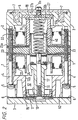
- the compressor shown in the drawings has a body composed of a main body 1 of square exterior cross-section transverse to the axis and a rear body 2 secured together by bolts 4 (Fig. 2) with washers 5.
- the bodies 1,2 are ribbed for cooling and strength.
- a cylinder head 3 is secured by bolts 3a (Fig. 6) in threaded holes 3b to the main body 1, with a one-piece sealing head gasket 6 of thin flexible plastics material, in this instance Melanex TM, interposed between them.
- the rear body 2 has an annular recess housing a filter 7 for the air passing through the compressor, covered by an end plate 8 secured to the rear body by nut and bolt 8a or similar.
- Axially reciprocatingly movable within the compressor is a piston 10 with a piston head 11 located within a cylinder 12 in the body 1 and a rear guide piston 13 slidably located in a piston guide 14 mounted in the main body 1 as described below.
- the piston head 11 has its peripherally outermost surface provided by an in situ moulded continuous band 15 of plastics material, to minimize leakage of air past the piston.
- the piston 10 Within the main body 1 are electromagnetic drive coils 22 (Fig. 2) and between the main body 1 and the rear body 2 there is a stator 23 composed of a conventional stack of magnetically permeable laminations.
- the piston 10 carries an armature 24 which is driven linearly by the coils 22 and the stator 23, in a known manner, so that the piston 10 is reciprocatingly driven by the linear motor thus constituted in one direction and by the restoring force of a spring arrangement 20 described below in the other direction.
- the reciprocation frequency is in accordance with the frequency of the applied AC voltage. The details of this driving arrangement need not be described further since it is well known.
- Fig. 1 shows that the cylinder surface 12a of the cylinder 12 is extended continuously rearwardly as inner surfaces 25a of two rearwardly projecting arms 25 of the body 1, these arms projecting through the stator 23.
- the inner surfaces 25a of these arms 25 are thus part-cylindrical surfaces of the same diameter as the cylinder surface 12a, and are formed in the same machining operation as the cylinder surface 12a, so as to have a very high degree of concentricity and coaxiality with the cylinder surface 12a.
- a typical forming process for these cylindrical surfaces 12a,25a is first a boring operation of the body part 1, followed by anodizing of the surfaces 12a,25a, and then by a highly accurate honing of the surfaces 12a,25a in a single honing operation by reference to a common axis.
- the rear ends of the surfaces 25a form registration surfaces for the exterior peripheral cylindrical surface 14a of the piston guide 14.
- This exterior cylindrical surface 14a of the guide 14 is also highly accurately machined so as to form an accurate register fit within the surfaces 25a, thus locating the piston guide 14 with a high degree of concentricity with the cylinder surface 12a.
- the axial location of the piston guide 14, in abutment with the stator 23 is achieved in this embodiment by a resilient rubber compression body 27 and a spring support 19 to be described below located between the piston guide 14 and an opposed end wall 27a of the rear body 2. Electrical isolation of the piston guide 14 from the main body 1 is achieved by the anodization of the mutually contacting surfaces 14a, 25a of these parts.
- the endmost one 23a of the laminations of the stator 23, which is abutted by the piston guide 14, is not a metal lamination but is a sheet of an electrically insulating material, such as a plastics material, in order to electrically isolate the piston guide 14 from the stator 23.
- the abutment of the piston guide 14 with this endmost lamination of the stator axially locates the piston guide 14.
- the piston guide 14 is thus resiliently clamped against the rigid stator 23 by the end wall 27a, through the resilient body 27.
- the piston head 11 has an in situ moulded continuous band 15 of low-friction plastics material acting as a piston ring.
- the guide piston 13 also has around its periphery an in situ moulded continuous band 13a of plastics material acting as a slide surface for the guide piston 13 on the piston guide 14.
- the low-friction plastics material used for the bands 13a, 15 in this embodiment of the invention is injected moulded to a thickness of about 1 mm.
- the material used is PPS (polyphenylene sulphide) blended with a percentage of a lubricating medium and a percentage of reinforcing fibre. This is machined after moulding to achieve highly accurate concentricity with the piston head or guide piston.
- PPS polyphenylene sulphide
- This is machined after moulding to achieve highly accurate concentricity with the piston head or guide piston.
- a particular advantage of this material is that it has almost the same coefficient of thermal expansion as aluminium, of which the piston head 11 and the guide piston 13 are conveniently made.
- the difference of coefficient of thermal expansion between the piston head or guide piston and the material of the piston ring bands 13a,15 is preferably less than 2 x 10 -6 /K.
- the piston 10 is in several parts, secured together by a bolt 16.
- the bolt 16 passes through the guide piston 13 and the armature 24 and is screwthreadedly engaged in a spacer part 17.
- the piston head 11 is also tightly screwthreadedly attached to the bolt 16.
- a nut 70 is secured on the bolt 16 to hold the flap 31 in place.
- Fig. 3 shows an air inlet passage 50 in the rear body part 2 having in it a flow-control valve body 51, which is screwthreadedly engaged with a screwthread 52 in the wall of the passage 50 and is thus adjustable in position along this screwthread 52.
- An air passage 53 allows the air to pass through the valve body 51, and the flow of air into the compressor is controlled by the positioning of a conical leading end 54 of the valve body 51 relative to an opposed shoulder 50a of the passage 50.
- a spring 55 acts on the valve body 51 to prevent its accidental rotation due for example to vibration.
- the passage 50 leads to the outside surface of the filter 7. Air passing through the filter 7 goes into a small gap 56 (Fig. 1) between the end plate 8 and the rear body 2, and then via passages 57 in the rear body 2 to inside the compressor, where it flows over the coils 22 to cool them in order to reach the back face of the piston head 11. This tortuous inlet path for the air helps to reduce-noise emitted by the compressor.
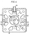
- Fig. 4 shows that the piston head 11 has four apertures 30 (not shown in Figs. 1 and 2) through it, which are covered at the head face of the piston head 11 by the flexible flap 31 (Fig. 1) to form a conventional flap valve, for admission of air from within the body of the compressor to the cylinder space in front of the piston on the reverse stroke of the piston.
- These apertures 30 in the piston head 11 are angled with respect to the axis of the piston.
- the axis of each aperture 30 is preferably about 30° to the axis of the compressor. A suitable range for this angle is 10° to 45°.
- stepped holes i.e. holes having portions circumferentially stepped around the piston axis
- the compression spring arrangement 20 shown in Figs. 1 and 2 this has two helical springs 20a and 20b, of mutually opposite helical coiling sense, arranged in series with a rotational bearing 40 mounted between their mutually opposed ends.
- the bearing 40 is supported only by the springs 20a, 20b and consists of a body 41 having axially projecting spigots 43 which radially locate the ends of the springs 20a, 20b.
- the spigots 43 are low-friction washers 42 on which the ends of the springs 20a, 20b bear. These washers are freely rotatable about the axis of the bearing 40 and are made of moulded PPS containing a lubricating medium and reinforcing fibre.
- the outer ends of the springs 20a and 20b are received respectively on an axial projection 19a on the spring support 19 and axial projection 44 of the guide piston 13.
- the rotational bearing 40 is freely movable radially and axially, so that it provides no constraint against any flexing of the spring system. It allows free relative rotational movement of the inner ends of the springs 20a and 20b, so that no net rotational force is applied by the springs to the piston 10.
- the opposite coiling senses of the two springs 20a and 20b tend to mean that their torsional forces are cancelled. Because they are relatively short, their tendency to deflect from the axis is small, and the free rotation of one end of each of them also reduces this tendency to deflect.
- the spring support 19 is radially located relative to the piston guide 14 by a shoulder 19b which makes a register fit with the rear end of the piston guide 14.
- Fig. 1 shows a mounting bracket 60 of the compressor and electrical leads 61, these parts being omitted from the other drawings, for simplicity.
- Figs. 1, 2 and 4 show that the cylinder body 1 has in it at its forward end face eight deep recesses 62 which are arranged in pairs, the two members of each pair being joined in each case by one of four shallower recesses 63 in the body end face. One of these shallower recesses 63 is in communication with the outlet 64 of the compressor.
- the cylinder head 3 has four recesses 65 in its face opposing the main body 1. The recesses 65 have sloping or bevelled rear faces 66 (two of these recesses can be seen in Fig. 6).
- Each of these recesses 65 is of a size so as to provide communication between two adjacent non-communicating deep recesses 62 of the main body 1.
- This gallery has a tortuous shape, which reduces noise emerging from the compressor.
- the volume of the gallery also provides a smoothing effect, reducing the pressure pulsing effect of the rapidly moving piston of the compressor.
- the gallery just described communicates with the interior of the cylinder 12 via a passage 67 opening in a side wall of the cylinder 12 and terminating at an outlet end 68 in the end face of the body 1, at a location corresponding to one of the recesses 65 of the cylinder head 3.
- the head gasket 6 lying between the cylinder head 3 and the main body 1, which seals around the head end of the cylinder 12, has four inwardly directed integral flap portions 69 one of which covers the outlet end 68 of the passage 67 thus forming a flap valve permitting flow of the compressed air out of the cylinder 12 but preventing reverse flow into the cylinder through the passage 67.
- This flap portion 69 moves within the recess 65 of the cylinder head 3 between its closed and open positions, and the length of its travel between these positions is determined by the angle of the bevel rear face 66 of the recess 65.
- the gasket 6 can be mounted in any one of four different positions angularly spaced by 90°, in each of which one of the integral flap portions 69 constitutes the flap valve controlling the flow of air in the passage 67.
- the cylinder head 3 can also be secured to the body 1 in any one of four positions, also angularly spaced by 90°.
- the four different recesses 65 of the cylinder head 3 have respectively different bevel angles of the bevelled rear faces 66. Consequently, the characteristic of the flap valve arrangement at the outlet of the passage 67 is different for each of the four positions of the cylinder head, because the travel of the valve member 69 is different and also the volume of the recess 65 is different in each case.
- the cylinder head 3 is reversible so that either of its main faces can face towards the main body 1 of the compressor.
- it has four of the recesses 65 on each of its two main faces and it also has two different central recesses 71, so that the effective volume of the cylinder 12 at its head end is different, depending on which of the two reverse positions of the cylinder head 3 is chosen. This again allows some adjustment of the characteristics of the compressor.
- Fig. 7 also shows different bevel angles of the rear faces of the recesses 65.
Landscapes
- Engineering & Computer Science (AREA)
- General Engineering & Computer Science (AREA)
- Mechanical Engineering (AREA)
- Chemical & Material Sciences (AREA)
- Combustion & Propulsion (AREA)
- Compressor (AREA)
- Compressors, Vaccum Pumps And Other Relevant Systems (AREA)
- Reciprocating, Oscillating Or Vibrating Motors (AREA)
- Electromagnetic Pumps, Or The Like (AREA)
Applications Claiming Priority (3)
| Application Number | Priority Date | Filing Date | Title |
|---|---|---|---|
| GB9311385 | 1993-06-02 | ||
| GB939311385A GB9311385D0 (en) | 1993-06-02 | 1993-06-02 | Compressor |
| EP94916346A EP0704023B1 (fr) | 1993-06-02 | 1994-06-02 | Compresseur |
Related Parent Applications (2)
| Application Number | Title | Priority Date | Filing Date |
|---|---|---|---|
| EP94916346A Division EP0704023B1 (fr) | 1993-06-02 | 1994-06-02 | Compresseur |
| EP94916346.3 Division | 1994-12-08 |
Publications (3)
| Publication Number | Publication Date |
|---|---|
| EP0796995A2 true EP0796995A2 (fr) | 1997-09-24 |
| EP0796995A3 EP0796995A3 (fr) | 1997-10-01 |
| EP0796995B1 EP0796995B1 (fr) | 1998-08-26 |
Family
ID=10736510
Family Applications (4)
| Application Number | Title | Priority Date | Filing Date |
|---|---|---|---|
| EP97100165A Expired - Lifetime EP0770779B1 (fr) | 1993-06-02 | 1994-06-02 | Compresseur |
| EP94916348A Expired - Lifetime EP0706613B1 (fr) | 1993-06-02 | 1994-06-02 | Compresseur |
| EP94916346A Expired - Lifetime EP0704023B1 (fr) | 1993-06-02 | 1994-06-02 | Compresseur |
| EP97109425A Expired - Lifetime EP0796995B1 (fr) | 1993-06-02 | 1994-06-02 | Compresseur |
Family Applications Before (3)
| Application Number | Title | Priority Date | Filing Date |
|---|---|---|---|
| EP97100165A Expired - Lifetime EP0770779B1 (fr) | 1993-06-02 | 1994-06-02 | Compresseur |
| EP94916348A Expired - Lifetime EP0706613B1 (fr) | 1993-06-02 | 1994-06-02 | Compresseur |
| EP94916346A Expired - Lifetime EP0704023B1 (fr) | 1993-06-02 | 1994-06-02 | Compresseur |
Country Status (9)
| Country | Link |
|---|---|
| US (3) | US5597294A (fr) |
| EP (4) | EP0770779B1 (fr) |
| JP (2) | JPH08510526A (fr) |
| AT (4) | ATE171515T1 (fr) |
| AU (3) | AU6803894A (fr) |
| DE (4) | DE69413038T2 (fr) |
| DK (1) | DK0706613T3 (fr) |
| GB (2) | GB9311385D0 (fr) |
| WO (3) | WO1994028308A1 (fr) |
Families Citing this family (32)
| Publication number | Priority date | Publication date | Assignee | Title |
|---|---|---|---|---|
| GB9311385D0 (en) * | 1993-06-02 | 1993-07-21 | Contech Int Ltd | Compressor |
| GB9424790D0 (en) * | 1994-12-08 | 1995-02-08 | Pegasus Airwave Ltd | Compressor |
| KR100224186B1 (ko) * | 1996-01-16 | 1999-10-15 | 윤종용 | 선형 압축기 |
| EP0864750A4 (fr) * | 1996-07-09 | 1999-06-09 | Sanyo Electric Co | Compresseur lineaire |
| GB2312835B (en) | 1996-12-18 | 1998-08-12 | Pegasus Airwave Ltd | Patient supports and methods of operating them |
| US6273688B1 (en) * | 1998-10-13 | 2001-08-14 | Matsushita Electric Industrial Co., Ltd. | Linear compressor |
| US6129527A (en) * | 1999-04-16 | 2000-10-10 | Litton Systems, Inc. | Electrically operated linear motor with integrated flexure spring and circuit for use in reciprocating compressor |
| JP2001227461A (ja) * | 2000-02-14 | 2001-08-24 | Matsushita Electric Ind Co Ltd | リニア圧縮機 |
| GB0005825D0 (en) * | 2000-03-11 | 2000-05-03 | Archfact Ltd | Compressor spring locator |
| TW504546B (en) * | 2000-10-17 | 2002-10-01 | Fisher & Amp Paykel Ltd | A linear compressor |
| GB0117834D0 (en) * | 2001-07-21 | 2001-09-12 | Archfact Ltd | Gasket |
| KR100548270B1 (ko) * | 2003-04-18 | 2006-02-02 | 엘지전자 주식회사 | 왕복동식 압축기의 고정자 체결 구조 |
| NZ526361A (en) * | 2003-05-30 | 2006-02-24 | Fisher & Paykel Appliances Ltd | Compressor improvements |
| US7777600B2 (en) * | 2004-05-20 | 2010-08-17 | Powerpath Technologies Llc | Eddy current inductive drive electromechanical liner actuator and switching arrangement |
| WO2006049510A2 (fr) * | 2004-11-02 | 2006-05-11 | Fisher & Paykel Appliances Limited | Compresseur lineaire |
| JP4520834B2 (ja) * | 2004-11-26 | 2010-08-11 | 日東工器株式会社 | 電磁往復動流体装置 |
| WO2009120670A1 (fr) * | 2008-03-26 | 2009-10-01 | Pollack Robert W | Systèmes et procédés pour énergiser et distribuer des fluides |
| DE102004062300A1 (de) * | 2004-12-23 | 2006-07-13 | BSH Bosch und Siemens Hausgeräte GmbH | Linearverdichter |
| JP4272178B2 (ja) | 2005-03-28 | 2009-06-03 | 日東工器株式会社 | 電磁往復動流体装置 |
| DE102009001315A1 (de) | 2009-03-04 | 2010-09-09 | Robert Bosch Gmbh | Kolbenpumpe |
| US9856866B2 (en) | 2011-01-28 | 2018-01-02 | Wabtec Holding Corp. | Oil-free air compressor for rail vehicles |
| BRPI1103647A2 (pt) * | 2011-07-07 | 2013-07-02 | Whirlpool Sa | disposiÇço entre componentes de compressor linear |
| BRPI1103447A2 (pt) * | 2011-07-19 | 2013-07-09 | Whirlpool Sa | feixe de molas para compressor e compressor provido de feixe de molas |
| BRPI1104172A2 (pt) * | 2011-08-31 | 2015-10-13 | Whirlpool Sa | compressor linear baseado em mecanismo oscilatório ressonante |
| CN104329238B (zh) * | 2013-07-22 | 2018-01-09 | 青岛海尔智能技术研发有限公司 | 直线压缩机及直线压缩机的活塞 |
| US9322401B2 (en) * | 2014-02-10 | 2016-04-26 | General Electric Company | Linear compressor |
| US9518572B2 (en) * | 2014-02-10 | 2016-12-13 | Haier Us Appliance Solutions, Inc. | Linear compressor |
| US9506460B2 (en) * | 2014-02-10 | 2016-11-29 | Haier Us Appliance Solutions, Inc. | Linear compressor |
| US9429150B2 (en) * | 2014-02-10 | 2016-08-30 | Haier US Appliances Solutions, Inc. | Linear compressor |
| JP6353771B2 (ja) * | 2014-11-25 | 2018-07-04 | 株式会社日立製作所 | リニアモータ及びリニアモータを搭載した圧縮機 |
| KR102238339B1 (ko) * | 2016-05-03 | 2021-04-09 | 엘지전자 주식회사 | 리니어 압축기 |
| DE102022213390A1 (de) * | 2022-12-09 | 2024-06-20 | Mahle International Gmbh | Kolben |
Citations (5)
| Publication number | Priority date | Publication date | Assignee | Title |
|---|---|---|---|---|
| FR1013829A (fr) * | 1950-03-04 | 1952-08-05 | Piston rotatif à gorge | |
| JPS57176343A (en) * | 1981-04-21 | 1982-10-29 | Isao Matsui | Piston |
| US4357915A (en) * | 1980-11-12 | 1982-11-09 | Monsour James R | Propeller and piston combination for internal combustion engines |
| EP0223288A1 (fr) * | 1985-11-06 | 1987-05-27 | Koninklijke Philips Electronics N.V. | Dispositif comprenant un piston alternatif et rotatif à effet hydrodynamique |
| US5100304A (en) * | 1990-05-09 | 1992-03-31 | Nitto Kohki Co., Ltd. | Solenoid-operated reciprocating pump |
Family Cites Families (23)
| Publication number | Priority date | Publication date | Assignee | Title |
|---|---|---|---|---|
| AT194870B (de) * | 1955-12-07 | 1958-01-25 | Licentia Gmbh | Elektromagnetischer Schwingkompressor vorzugsweise für Kältemaschinen |
| SE355215B (fr) * | 1971-03-17 | 1973-04-09 | Atlas Copco Ab | |
| DE2122939A1 (de) * | 1971-05-10 | 1972-11-23 | Mikuni Jukogyo K.K., Osaka (Japan) | Schmiermittelfreier Kolben mit Kolbenring für einen Gaskompressor |
| FR2158583A6 (fr) * | 1971-08-31 | 1973-06-15 | Barthalon Maurice | |
| CH549896A (de) * | 1972-09-22 | 1974-05-31 | Landis & Gyr Ag | Schwinganker - kolbenpumpe. |
| JPS51116411A (en) * | 1975-04-04 | 1976-10-13 | Man Design Kk | An enclosed-type electromagnetic-starting compressor electromagnetic-s tarting compressor |
| LU73529A1 (fr) * | 1975-10-06 | 1977-07-15 | ||
| US4090816A (en) * | 1975-10-14 | 1978-05-23 | Man Design Co., Ltd. | Electromagnetic fluid operating apparatus |
| US4067093A (en) * | 1976-05-24 | 1978-01-10 | Dynamic Seals Incorporated | Piston assembly and method for manufacturing |
| US4261689A (en) * | 1979-02-08 | 1981-04-14 | Man Design Co., Ltd. | Electro-magnetic fluid pump |
| JPS57149657A (en) * | 1981-03-12 | 1982-09-16 | Sumitomo Bakelite Co Ltd | High precison piston and its manufacturing method |
| JPS5987285A (ja) * | 1982-11-12 | 1984-05-19 | Man Design Kk | 電磁往復動圧縮機 |
| SU1460406A1 (ru) * | 1985-01-04 | 1989-02-23 | Омский политехнический институт | Электромагнитный компрессор |
| JPH0633768B2 (ja) | 1985-03-11 | 1994-05-02 | 日東工器株式会社 | 電磁往復動式ポンプ |
| WO1987003342A1 (fr) * | 1985-11-21 | 1987-06-04 | Industria De Motores Anauger Ltda. | Pompe vibratoire |
| US4721440A (en) * | 1987-02-13 | 1988-01-26 | Mechanical Technology Incorporated | Linear gas compressor |
| JPH0219598Y2 (fr) * | 1987-05-30 | 1990-05-30 | ||
| JPH059508Y2 (fr) * | 1987-06-17 | 1993-03-09 | ||
| US4966533A (en) * | 1987-07-14 | 1990-10-30 | Kabushiki Kaisha Nagano Keiki Seisakusho | Vacuum pump with rotational sliding piston support |
| US4776776A (en) * | 1987-08-24 | 1988-10-11 | The Devilbiss Company | Small pump valve plate assembly |
| JPH03253776A (ja) * | 1990-03-05 | 1991-11-12 | Nitto Kohki Co Ltd | 電磁往復動ポンプ |
| JPH04121477U (ja) * | 1991-04-16 | 1992-10-29 | サンデン株式会社 | フリーピストン型コンプレツサー |
| GB9311385D0 (en) * | 1993-06-02 | 1993-07-21 | Contech Int Ltd | Compressor |
-
1993
- 1993-06-02 GB GB939311385A patent/GB9311385D0/en active Pending
-
1994
- 1994-06-02 DE DE69413038T patent/DE69413038T2/de not_active Expired - Fee Related
- 1994-06-02 AT AT97100165T patent/ATE171515T1/de not_active IP Right Cessation
- 1994-06-02 WO PCT/GB1994/001195 patent/WO1994028308A1/fr active IP Right Grant
- 1994-06-02 JP JP7500429A patent/JPH08510526A/ja active Pending
- 1994-06-02 AU AU68038/94A patent/AU6803894A/en not_active Abandoned
- 1994-06-02 EP EP97100165A patent/EP0770779B1/fr not_active Expired - Lifetime
- 1994-06-02 AT AT94916346T patent/ATE170598T1/de not_active IP Right Cessation
- 1994-06-02 US US08/556,901 patent/US5597294A/en not_active Expired - Fee Related
- 1994-06-02 DK DK94916348.9T patent/DK0706613T3/da active
- 1994-06-02 JP JP7500431A patent/JPH08510527A/ja active Pending
- 1994-06-02 AT AT94916348T patent/ATE157430T1/de not_active IP Right Cessation
- 1994-06-02 WO PCT/GB1994/001193 patent/WO1994028306A1/fr active IP Right Grant
- 1994-06-02 DE DE69412869T patent/DE69412869T2/de not_active Expired - Fee Related
- 1994-06-02 AU AU68039/94A patent/AU6803994A/en not_active Abandoned
- 1994-06-02 DE DE69405239T patent/DE69405239T2/de not_active Expired - Fee Related
- 1994-06-02 EP EP94916348A patent/EP0706613B1/fr not_active Expired - Lifetime
- 1994-06-02 US US08/556,903 patent/US5603612A/en not_active Expired - Fee Related
- 1994-06-02 GB GB9524175A patent/GB2294297B/en not_active Expired - Fee Related
- 1994-06-02 EP EP94916346A patent/EP0704023B1/fr not_active Expired - Lifetime
- 1994-06-02 WO PCT/GB1994/001194 patent/WO1994028307A1/fr active Application Filing
- 1994-06-02 EP EP97109425A patent/EP0796995B1/fr not_active Expired - Lifetime
- 1994-06-02 AU AU68040/94A patent/AU6804094A/en not_active Abandoned
- 1994-06-02 AT AT97109425T patent/ATE170263T1/de not_active IP Right Cessation
- 1994-06-02 DE DE69413565T patent/DE69413565T2/de not_active Expired - Fee Related
-
1997
- 1997-01-29 US US08/790,486 patent/US5727932A/en not_active Expired - Fee Related
Patent Citations (5)
| Publication number | Priority date | Publication date | Assignee | Title |
|---|---|---|---|---|
| FR1013829A (fr) * | 1950-03-04 | 1952-08-05 | Piston rotatif à gorge | |
| US4357915A (en) * | 1980-11-12 | 1982-11-09 | Monsour James R | Propeller and piston combination for internal combustion engines |
| JPS57176343A (en) * | 1981-04-21 | 1982-10-29 | Isao Matsui | Piston |
| EP0223288A1 (fr) * | 1985-11-06 | 1987-05-27 | Koninklijke Philips Electronics N.V. | Dispositif comprenant un piston alternatif et rotatif à effet hydrodynamique |
| US5100304A (en) * | 1990-05-09 | 1992-03-31 | Nitto Kohki Co., Ltd. | Solenoid-operated reciprocating pump |
Non-Patent Citations (1)
| Title |
|---|
| PATENT ABSTRACTS OF JAPAN vol. 7, no. 24 (M-189) [1169] , 29 January 1983 & JP 57 176343 A (ISAO MATSUI), 29 October 1982, * |
Also Published As
Similar Documents
| Publication | Publication Date | Title |
|---|---|---|
| EP0704023B1 (fr) | Compresseur | |
| KR101305404B1 (ko) | 막 펌프 | |
| US20070041856A1 (en) | Linear compressor | |
| CN108343776B (zh) | 电动阀以及冷冻循环系统 | |
| CA2268343A1 (fr) | Pompe a piston et procede permettant de reduire les bouchons de vapeur | |
| US5395218A (en) | Fluid pump apparatus | |
| EP0796395B1 (fr) | Compresseur | |
| GB2303886A (en) | Electromagnetic reciprocating compressor | |
| US5564908A (en) | Fluid pump having magnetic drive | |
| US11808256B2 (en) | Compressor including discharge plenum | |
| GB2303887A (en) | Electromagnetic reciprocating compressor | |
| EP1266140B1 (fr) | Pied de positionnement d'un ressort de compresseur | |
| EP0167274A2 (fr) | Pompe | |
| JP3331489B2 (ja) | 対向ピストン形圧縮機 | |
| US20070041854A1 (en) | Linear compressor, particularly refrigerant compressor | |
| EP0479443A1 (fr) | Compresseurs pour appareil de réfrigération | |
| KR20210120657A (ko) | 리니어 모터 및 이를 구비하는 리니어 압축기 | |
| KR100273440B1 (ko) | 리니어 압축기 | |
| US20050118043A1 (en) | Unit utilizing current to control reciprocation for pushing fluids | |
| KR101265132B1 (ko) | 왕복동식 압축기 | |
| EP1726827B1 (fr) | Pompe électromagnétique | |
| KR100216197B1 (ko) | 마그네트식 다이아프램 펌프 | |
| CN116591927A (zh) | 一种双级线性压缩机 | |
| JPH03263558A (ja) | フリーピストン式膨脹エンジン |
Legal Events
| Date | Code | Title | Description |
|---|---|---|---|
| PUAI | Public reference made under article 153(3) epc to a published international application that has entered the european phase |
Free format text: ORIGINAL CODE: 0009012 |
|
| PUAL | Search report despatched |
Free format text: ORIGINAL CODE: 0009013 |
|
| 17P | Request for examination filed |
Effective date: 19970702 |
|
| AC | Divisional application: reference to earlier application |
Ref document number: 704023 Country of ref document: EP |
|
| AK | Designated contracting states |
Kind code of ref document: A2 Designated state(s): AT BE DE DK ES FR IE IT NL SE |
|
| AK | Designated contracting states |
Kind code of ref document: A3 Designated state(s): AT BE DE DK ES FR IE IT NL SE |
|
| GRAG | Despatch of communication of intention to grant |
Free format text: ORIGINAL CODE: EPIDOS AGRA |
|
| 17Q | First examination report despatched |
Effective date: 19971031 |
|
| GRAG | Despatch of communication of intention to grant |
Free format text: ORIGINAL CODE: EPIDOS AGRA |
|
| GRAH | Despatch of communication of intention to grant a patent |
Free format text: ORIGINAL CODE: EPIDOS IGRA |
|
| GRAH | Despatch of communication of intention to grant a patent |
Free format text: ORIGINAL CODE: EPIDOS IGRA |
|
| GRAA | (expected) grant |
Free format text: ORIGINAL CODE: 0009210 |
|
| AC | Divisional application: reference to earlier application |
Ref document number: 704023 Country of ref document: EP |
|
| AK | Designated contracting states |
Kind code of ref document: B1 Designated state(s): AT BE DE DK ES FR IE IT NL SE |
|
| PG25 | Lapsed in a contracting state [announced via postgrant information from national office to epo] |
Ref country code: NL Free format text: LAPSE BECAUSE OF FAILURE TO SUBMIT A TRANSLATION OF THE DESCRIPTION OR TO PAY THE FEE WITHIN THE PRESCRIBED TIME-LIMIT Effective date: 19980826 Ref country code: IT Free format text: LAPSE BECAUSE OF FAILURE TO SUBMIT A TRANSLATION OF THE DESCRIPTION OR TO PAY THE FEE WITHIN THE PRESCRIBED TIME-LIMIT;WARNING: LAPSES OF ITALIAN PATENTS WITH EFFECTIVE DATE BEFORE 2007 MAY HAVE OCCURRED AT ANY TIME BEFORE 2007. THE CORRECT EFFECTIVE DATE MAY BE DIFFERENT FROM THE ONE RECORDED. Effective date: 19980826 Ref country code: FR Free format text: LAPSE BECAUSE OF FAILURE TO SUBMIT A TRANSLATION OF THE DESCRIPTION OR TO PAY THE FEE WITHIN THE PRESCRIBED TIME-LIMIT Effective date: 19980826 Ref country code: ES Free format text: THE PATENT HAS BEEN ANNULLED BY A DECISION OF A NATIONAL AUTHORITY Effective date: 19980826 |
|
| REF | Corresponds to: |
Ref document number: 170263 Country of ref document: AT Date of ref document: 19980915 Kind code of ref document: T |
|
| REF | Corresponds to: |
Ref document number: 69412869 Country of ref document: DE Date of ref document: 19981001 |
|
| REG | Reference to a national code |
Ref country code: IE Ref legal event code: FG4D |
|
| PG25 | Lapsed in a contracting state [announced via postgrant information from national office to epo] |
Ref country code: DK Free format text: LAPSE BECAUSE OF FAILURE TO SUBMIT A TRANSLATION OF THE DESCRIPTION OR TO PAY THE FEE WITHIN THE PRESCRIBED TIME-LIMIT Effective date: 19981126 |
|
| EN | Fr: translation not filed | ||
| NLV1 | Nl: lapsed or annulled due to failure to fulfill the requirements of art. 29p and 29m of the patents act | ||
| PLBE | No opposition filed within time limit |
Free format text: ORIGINAL CODE: 0009261 |
|
| STAA | Information on the status of an ep patent application or granted ep patent |
Free format text: STATUS: NO OPPOSITION FILED WITHIN TIME LIMIT |
|
| 26N | No opposition filed | ||
| PGFP | Annual fee paid to national office [announced via postgrant information from national office to epo] |
Ref country code: SE Payment date: 20020625 Year of fee payment: 9 Ref country code: IE Payment date: 20020625 Year of fee payment: 9 Ref country code: AT Payment date: 20020625 Year of fee payment: 9 |
|
| PGFP | Annual fee paid to national office [announced via postgrant information from national office to epo] |
Ref country code: BE Payment date: 20020626 Year of fee payment: 9 |
|
| PGFP | Annual fee paid to national office [announced via postgrant information from national office to epo] |
Ref country code: DE Payment date: 20020629 Year of fee payment: 9 |
|
| PG25 | Lapsed in a contracting state [announced via postgrant information from national office to epo] |
Ref country code: IE Free format text: LAPSE BECAUSE OF NON-PAYMENT OF DUE FEES Effective date: 20030602 Ref country code: AT Free format text: LAPSE BECAUSE OF NON-PAYMENT OF DUE FEES Effective date: 20030602 |
|
| PG25 | Lapsed in a contracting state [announced via postgrant information from national office to epo] |
Ref country code: SE Free format text: LAPSE BECAUSE OF NON-PAYMENT OF DUE FEES Effective date: 20030603 |
|
| PG25 | Lapsed in a contracting state [announced via postgrant information from national office to epo] |
Ref country code: BE Free format text: LAPSE BECAUSE OF NON-PAYMENT OF DUE FEES Effective date: 20030630 |
|
| BERE | Be: lapsed |
Owner name: *PEGASUS AIRWAVE LTD Effective date: 20030630 |
|
| PG25 | Lapsed in a contracting state [announced via postgrant information from national office to epo] |
Ref country code: DE Free format text: LAPSE BECAUSE OF NON-PAYMENT OF DUE FEES Effective date: 20040101 |
|
| EUG | Se: european patent has lapsed | ||
| REG | Reference to a national code |
Ref country code: IE Ref legal event code: MM4A |