EP0796706B1 - Hochgeschwindigkeitssperrvorrichtung für einen Flüssigkeitsstrahl - Google Patents
Hochgeschwindigkeitssperrvorrichtung für einen Flüssigkeitsstrahl Download PDFInfo
- Publication number
- EP0796706B1 EP0796706B1 EP97301849A EP97301849A EP0796706B1 EP 0796706 B1 EP0796706 B1 EP 0796706B1 EP 97301849 A EP97301849 A EP 97301849A EP 97301849 A EP97301849 A EP 97301849A EP 0796706 B1 EP0796706 B1 EP 0796706B1
- Authority
- EP
- European Patent Office
- Prior art keywords
- blocking member
- high pressure
- stream
- rotary actuator
- housing
- Prior art date
- Legal status (The legal status is an assumption and is not a legal conclusion. Google has not performed a legal analysis and makes no representation as to the accuracy of the status listed.)
- Expired - Lifetime
Links
- XLYOFNOQVPJJNP-UHFFFAOYSA-N water Substances O XLYOFNOQVPJJNP-UHFFFAOYSA-N 0.000 title abstract description 68
- 230000000903 blocking effect Effects 0.000 claims abstract description 97
- 238000001816 cooling Methods 0.000 claims abstract description 5
- 239000012530 fluid Substances 0.000 claims description 34
- 239000007788 liquid Substances 0.000 claims description 12
- 230000008878 coupling Effects 0.000 claims description 4
- 238000010168 coupling process Methods 0.000 claims description 4
- 238000005859 coupling reaction Methods 0.000 claims description 4
- 238000000034 method Methods 0.000 abstract description 9
- 235000013305 food Nutrition 0.000 abstract description 2
- 230000007246 mechanism Effects 0.000 description 6
- 239000010935 stainless steel Substances 0.000 description 6
- 229910001220 stainless steel Inorganic materials 0.000 description 6
- 230000002452 interceptive effect Effects 0.000 description 4
- 230000009471 action Effects 0.000 description 2
- 230000003628 erosive effect Effects 0.000 description 2
- 230000006870 function Effects 0.000 description 2
- 238000012423 maintenance Methods 0.000 description 2
- 239000000463 material Substances 0.000 description 2
- 230000002441 reversible effect Effects 0.000 description 2
- 229920004943 Delrin® Polymers 0.000 description 1
- RTAQQCXQSZGOHL-UHFFFAOYSA-N Titanium Chemical compound [Ti] RTAQQCXQSZGOHL-UHFFFAOYSA-N 0.000 description 1
- HZEWFHLRYVTOIW-UHFFFAOYSA-N [Ti].[Ni] Chemical compound [Ti].[Ni] HZEWFHLRYVTOIW-UHFFFAOYSA-N 0.000 description 1
- 238000010521 absorption reaction Methods 0.000 description 1
- 229910045601 alloy Inorganic materials 0.000 description 1
- 239000000956 alloy Substances 0.000 description 1
- 229910052782 aluminium Inorganic materials 0.000 description 1
- XAGFODPZIPBFFR-UHFFFAOYSA-N aluminium Chemical compound [Al] XAGFODPZIPBFFR-UHFFFAOYSA-N 0.000 description 1
- 239000002173 cutting fluid Substances 0.000 description 1
- 230000001066 destructive effect Effects 0.000 description 1
- 238000010586 diagram Methods 0.000 description 1
- 229910003460 diamond Inorganic materials 0.000 description 1
- 239000010432 diamond Substances 0.000 description 1
- 239000000428 dust Substances 0.000 description 1
- 230000000694 effects Effects 0.000 description 1
- 230000005611 electricity Effects 0.000 description 1
- 238000007373 indentation Methods 0.000 description 1
- 230000013011 mating Effects 0.000 description 1
- 229910052751 metal Inorganic materials 0.000 description 1
- 239000002184 metal Substances 0.000 description 1
- 239000000203 mixture Substances 0.000 description 1
- 229910001000 nickel titanium Inorganic materials 0.000 description 1
- 238000005192 partition Methods 0.000 description 1
- 230000002028 premature Effects 0.000 description 1
- 229910001285 shape-memory alloy Inorganic materials 0.000 description 1
- 239000000126 substance Substances 0.000 description 1
- 239000010936 titanium Substances 0.000 description 1
- 229910052719 titanium Inorganic materials 0.000 description 1
Images


Classifications
-
- B—PERFORMING OPERATIONS; TRANSPORTING
- B26—HAND CUTTING TOOLS; CUTTING; SEVERING
- B26F—PERFORATING; PUNCHING; CUTTING-OUT; STAMPING-OUT; SEVERING BY MEANS OTHER THAN CUTTING
- B26F3/00—Severing by means other than cutting; Apparatus therefor
- B26F3/004—Severing by means other than cutting; Apparatus therefor by means of a fluid jet
- B26F2003/006—Severing by means other than cutting; Apparatus therefor by means of a fluid jet having a shutter or water jet deflector
-
- Y—GENERAL TAGGING OF NEW TECHNOLOGICAL DEVELOPMENTS; GENERAL TAGGING OF CROSS-SECTIONAL TECHNOLOGIES SPANNING OVER SEVERAL SECTIONS OF THE IPC; TECHNICAL SUBJECTS COVERED BY FORMER USPC CROSS-REFERENCE ART COLLECTIONS [XRACs] AND DIGESTS
- Y10—TECHNICAL SUBJECTS COVERED BY FORMER USPC
- Y10T—TECHNICAL SUBJECTS COVERED BY FORMER US CLASSIFICATION
- Y10T137/00—Fluid handling
- Y10T137/0318—Processes
- Y10T137/0396—Involving pressure control
-
- Y—GENERAL TAGGING OF NEW TECHNOLOGICAL DEVELOPMENTS; GENERAL TAGGING OF CROSS-SECTIONAL TECHNOLOGIES SPANNING OVER SEVERAL SECTIONS OF THE IPC; TECHNICAL SUBJECTS COVERED BY FORMER USPC CROSS-REFERENCE ART COLLECTIONS [XRACs] AND DIGESTS
- Y10—TECHNICAL SUBJECTS COVERED BY FORMER USPC
- Y10T—TECHNICAL SUBJECTS COVERED BY FORMER US CLASSIFICATION
- Y10T137/00—Fluid handling
- Y10T137/206—Flow affected by fluid contact, energy field or coanda effect [e.g., pure fluid device or system]
- Y10T137/2076—Utilizing diverse fluids
-
- Y—GENERAL TAGGING OF NEW TECHNOLOGICAL DEVELOPMENTS; GENERAL TAGGING OF CROSS-SECTIONAL TECHNOLOGIES SPANNING OVER SEVERAL SECTIONS OF THE IPC; TECHNICAL SUBJECTS COVERED BY FORMER USPC CROSS-REFERENCE ART COLLECTIONS [XRACs] AND DIGESTS
- Y10—TECHNICAL SUBJECTS COVERED BY FORMER USPC
- Y10T—TECHNICAL SUBJECTS COVERED BY FORMER US CLASSIFICATION
- Y10T137/00—Fluid handling
- Y10T137/206—Flow affected by fluid contact, energy field or coanda effect [e.g., pure fluid device or system]
- Y10T137/218—Means to regulate or vary operation of device
- Y10T137/2202—By movable element
- Y10T137/2213—Electrically-actuated element [e.g., electro-mechanical transducer]
-
- Y—GENERAL TAGGING OF NEW TECHNOLOGICAL DEVELOPMENTS; GENERAL TAGGING OF CROSS-SECTIONAL TECHNOLOGIES SPANNING OVER SEVERAL SECTIONS OF THE IPC; TECHNICAL SUBJECTS COVERED BY FORMER USPC CROSS-REFERENCE ART COLLECTIONS [XRACs] AND DIGESTS
- Y10—TECHNICAL SUBJECTS COVERED BY FORMER USPC
- Y10T—TECHNICAL SUBJECTS COVERED BY FORMER US CLASSIFICATION
- Y10T137/00—Fluid handling
- Y10T137/6416—With heating or cooling of the system
- Y10T137/6525—Air heated or cooled [fan, fins, or channels]
Definitions
- This invention relates generally to a product cutter utilizing a high pressure fluid jet, an apparatus for selectively interrupting the flow of a stream of high pressure water used to cut products according to the preambles of claims 1 and 6, defined in view of WO-A-93/10950.
- Fluid jets have been used to cut food, paper and other products for years. The advantages are numerous; there are no blades that need to be sharpened or replaced, no dust is created, and cuts can be quick and clean.
- the cutting is done with a thin, high pressure, high velocity stream of water or other fluid. Pressurized water is ejected from a very small orifice to create the jet. When the jet touches the product, a thin slice is removed without any appreciable water being absorbed into the product.
- a linear actuator pressurized by air that forces a plunger pin into the path of the water jet is a generally known tool for performing this method.
- a spring provides a retracting force for the plunger pin.
- Existing plunger pin devices are capable of reaching closure times of 50-90ms and thereby limit the speed at which products may be cut by the water jet.
- U.S. Patent No. 4,693,153 discloses another water jet interruption technique.
- a second high pressure fluid is directed at the object cutting jet so as to disperse the latter and impair its object cutting properties.
- the device that controls the second fluid flow is similar to the plunger pin device.
- a solenoid device within the jet obstructer device controls the fluid flow from the jet obstructer device.
- An energized solenoid closes a plunger mechanism that is normally held in an open position by a spring. In the open position the mechanism provides high pressure fluid to interrupt the object cutting water jet. Similar to the plunger pin device, this device also lacks the high speed interruption capabilities necessary for cutting products as rapidly as may be desired.
- the devices currently in use do not effectively and efficiently solve the problem of cutting precise shapes at high speeds that require a high frequency of water jet interruption. Accordingly, the present invention was developed, and provides significant advantages over previous devices or methods to cut shapes with fluid jets.
- an apparatus for controlling the flow of a stream of high pressure fluid used for cutting an object includes a main housing with a blocking device and a rotary actuator disposed within.
- the rotary actuator generates a rotary output torque.
- the apparatus also includes a coupling mechanism that provides a couple between the blocking device and the rotary actuator to transmit the rotary output torque from the rotary actuator to the blocking device to cause the blocking device to shift into the path of travel of the stream of high pressure fluid to disrupt the flow of the high pressure stream and out of the path of the high pressure fluid to not disrupt the flow of the high pressure stream.
- the blocking device is a rod and the coupling mechanism couples one end portion of the rod to the rotary actuator.
- the rod is adjustable orthogonally to the flow of the high pressure stream. Also, the rod is removable from the housing and rotatable within the housing.
- the rotary actuator toggles to predefined limits that are controlled by a controlling mechanism.
- high pressure air is directed past the rotary actuator for cooling the rotary actuator.
- the directed high pressure air is further directed to expel fluid from the housing remaining from the disrupted flow of the high pressure stream.
- the invention provides a new and improved method and apparatus for controlling the flow of a stream of high pressure fluid used for cutting. Because the method and apparatus does not require the use of a plunger pin device, the disadvantages associated with the use of connectors, briefly described above, are avoided.
- the high speed water jet blocker 10 includes a main housing 18, with a projecting portion 16.
- the main housing 18 and the projecting portion 16 include cavities with a connecting passageway for housing a rotary actuator 32, a blocking bar 22, an output shaft 30, a pivot arm 28, vertical pins 26 and a collar 24b.
- the main housing 18 and projecting portion 16 are preferably composed of a high density plastic, such as Delrin®.
- the high speed water jet blocker 10 shown in FIGURE 2 is in an upright position with a top and bottom where the projecting portion 16 of the water jet blocker 10 is attached to and flush with the base of the main housing 18.
- the views of FIGURES 1A and 1B are toward the bottom of the water jet blocker 10.
- a downwardly extending counterbore cavity 19 that opens at the top of the projecting portion 16.
- the open upper end of the counterbore cavity 19 receives a nozzle 14 attached to the discharge end of a high pressure water line (not shown).
- the nozzle 14 supplies (discharges) a very fine, high pressure, high speed fluid or water jet 12 in a vertically descending direction into counterbore cavity 19.
- a small opening 20 at the base of counterbore cavity 19 provides an opening for the high speed water jet 12 to exit projecting portion 16 for the purpose of cutting products located below the blocker 10.
- Small opening 20 is large enough to avoid interfering with the flow of water jet 12.
- a disk-shaped carbide insert 23 surrounds small opening 20, protecting it from wear due to high pressure deflected fluid.
- the pivotal blocking bar 22 has two operational positions within the counterbore cavity 19. As shown in FIGURE 1A, the first operational position is a water jet blocking or interrupting position. Blocking bar 22 provides interruption of the flow of the water jet 12 because of its location over small opening 20. As shown in FIGURE 1B, the other operational position is a cutting position since blocking bar 22 is dislocated laterally from small opening 20 thereby providing an uninterrupted flow of water jet 12.
- a lateral passageway 24a creates a path from the counterbore cavity 19 to a lower cavity 25 within main housing 18.
- Lower cavity 25 creates an opening at the base of main housing 18 and extends vertically to a level higher than passageway 24a, but lower than the top of projecting portion 16, as shown in FIGURE 2.
- Blocking bar 22 is disposed within passageway 24a and supported by a collar 24b to extend into lower cavity 25.
- Collar 24b is preferably composed of stainless steel and press fit within the passageway 24a.
- An O-ring seal 24c is used to prevent water from entering lower cavity 25.
- the O-ring seal is seated within a groove formed in the internal diameter of the collar 24b.
- the internal ends of the collar 24b are beveled allowing the bar to pivot freely side-to-side, as discussed more fully below, without interference with the collar.
- the proximal end of blocking bar 22 that extends into the lower cavity 25 extends between a pair of spaced apart pins 26 extending transversely downwardly from the distal end of a pivot arm 28.
- the proximal end of pivot arm 28 is securedly connected to an output shaft 30.
- output shaft 30 extends through a vertical opening 31 at the top of lower cavity 25 from a rotary actuator 32 contained in an upper cavity 33 formed within main housing 18.
- the upper cavity has a base that is approximately at the same vertical elevation as the top of projecting portion 16.
- the upper and lower cavities are approximately equal in diameter and both have a larger diameter than the diameter of counterbore cavity 19.
- upper cavity 33 is open at the top of main housing 18. Both cavity openings are closed by corresponding cavity caps 39.
- the output shaft 30, pivoted by the rotary actuator 32 is at a maximum counter-clockwise position.
- pivot arm 28 is also at a maximum counter-clockwise position, thereby pivoting the blocking bar 22 in a clockwise direction about collar 24b to block the flow of water jet 12.
- rotary actuator 32 rotates the output shaft 30 and pivot arm 28 to a fully clockwise position.
- the blocking bar 22 is pivoted in a counter-clockwise direction about collar 24b, thereby retracting the blocking bar 22 out of the path of the water jet 12 to allow the water jet to flow through the water jet blocker 10.
- the total range of rotation of the output shaft 30 and pivot arm 28 is approximately forty-five degrees with somewhat equal rotation relative to a longitudinal centerline 46 extending between the centers of small opening 20 and output shaft 30.
- the longitudinal centerline 47 of passageway 24a is offset slightly from longitudinal centerline 46. Passageway 24a is offset so blocking bar 22 covers small opening 20 when the output shaft 30 and pivot arm 28 are in the fully counter-clockwise position and so blocking bar 22 does not block small opening 20 when the output shaft 30 and pivot arm 28 are in the fully clockwise position.
- An exhaust port 44 provides a lateral opening from counterbore cavity 19 at a position on the counterbore cavity 19 diametrically opposed from passageway 24a.
- the base of exhaust port 44 is shown at the same elevation as blocking bar 22.
- Exhaust port 44 provides a route for fluid to escape counterbore cavity 19 during water jet interruption.
- FIGURES 1A, 1B and 2 A further aspect of the present invention is illustrated in FIGURES 1A, 1B and 2.
- An annular cavity 40 is defined by the internal diameter of the upper cavity 33 and a metallic sleeve 43.
- the sleeve 43 is composed of aluminum or similar metal.
- Sleeve 43 includes a cylindrical body portion 43a and upper and lower flanges 43b and 43c that extend radially outwardly from the upper and lower ends of the sleeve.
- the sleeve body portion 43a snugly surrounds the lower portion 41 of the actuator, and the outer circumferences of the flanges 43b and 43c snugly engage against the inner surface of the main housing 18 that defines the outer diameter of the annular cavity 40.
- annular cavity 40 is formed by the flanges 43b and 43c and body portion 43a, respectively, of the sleeve 43. Also, sleeve 43 occupies the space in upper cavity 33 below an upper portion of rotary actuator 32 not occupied by the lower portion 41 of rotary actuator 32 and annular cavity 40.
- An inlet port 38 leads into the annular cavity 40, and a pair of outlet ports 35a and 35b leads away from annular cavity 40.
- the input port 38 is located at the lower portion of the annular cavity 40 along longitudinal centerline 46.
- Input port 38 is connectable to a pressurized air source. Also, input port 38 is located on the main housing 18 distally opposed from projecting portion 16.
- Exhaust ports 35a and 35b are located approximately equidistant from longitudinal centerline 46.
- the exhaust ports connect to air passageways 42a and 42b leading between annular cavity 40 and counterbore cavity 19.
- Air passageways 42a and 42b extend down main housing 18 angled slightly towards projecting portion 16.
- air passageways 42a and 42b extend horizontally at an elevation approximately equal to the elevation of passageway 24a.
- the horizontal sections of the air passageways 42a and 42b angle toward the center of counterbore cavity 19 to deliver, through openings in counterbore cavity 19, high pressure air on either side of blocking bar 22.
- pressurized air follows air path 36 and enters inlet port 38, travels through annular cavity 40, exits through exhaust ports 35a and 35b, travels through passageways 42a and42b, and enters counterbore cavity 19 to blow excess or deflected fluid out of counterbore cavity 19 through exhaust port 44.
- Pressurized air continuously flows thus providing a cooling effect on sleeve 43 which conducts heat away from rotary actuator 32.
- sleeve 43 in addition to defining portions of annular cavity 40, also serves to seal the lower portion 41 of the rotary actuator 32 from moisture. Such moisture may be latent within the air supplied to the jet blocker 10 through input port 38. Also, the moisture may originate from the water jet 12 and may "back up” into the cavity 40 through the air passageways 42a and 42b and exhaust ports 35a and 35b.
- Rotary actuator 32 is a device that converts electric energy into a controlled rotary force that is quickly reversible in the rotary direction.
- the rotary actuator can pivot the pivot arm 28 into the path of the water jet 12 and reverse direction to retract the pivot arm out of the path of the water jet in as little as 5-6 milliseconds.
- Electrical energy is provided to a rotary actuator 32 from a power supply through power cord port 37 located above input port 38, as shown in FIGURE 2.
- the water jet blocker 10 is controlled by and used in various systems.
- the present invention uses some form of processing unit or computer 49 to supply the rotary actuator 32 with a controlled electrical energy supply.
- Processing unit 49 controls an electrical signal sent to rotary actuator 32, thereby controlling the cutting pattern of water jet blocker 10.
- Multiple water jet blockers can be used in conjunction with a computer controller for performing simultaneous high speed interactive cuts.
- Some systems that incorporate the blocking device of the present invention are designed to operate continuously or with very little down time thereby requiring a cutting device with effective and efficient maintenance. Due to the destructive force of high speed water jet 12, blocking bar 22 is eventually eroded away, thereby reducing the efficient feature of the system.
- One solution is a bar adjustment mechanism 27 and 29 within the water jet blocker 10.
- a knurled lead screw 29 controls the longitudinal position of an adjusting backstop 27. As shown in FIGURES 1A, 1B and 2, screw 29 is sealed with respect to housing 18 by an O-ring in a through hole located below input port 38 at approximately the elevation center of lower cavity 25. Also, the thread, leading portion of screw 29 extends into lower cavity 25 to a position free from interfering with pivot arm 28.
- Backstop 27 is positioned within lower cavity 25.
- the backstop includes a rear portion that includes an upwardly extending abutment wall having a threaded opening formed therein to receive the complementarily threaded lead portion of screw 29.
- the backstop also includes a front or leading end that abuts against the proximal (rear) end of blocking bar 22.
- Rotation of screw 29 adjusts the longitudinal (forward and rearward) position of backstop 27, thereby correspondingly adjusting the longitudinal position of blocking bar 22.
- Adjustment of the longitudinal position of the bar within the blocker 10 provides multiple water jet contact locations along the length of the bar, effectively delaying failure of the bar.
- the bar could be composed of titanium, carbide or a memory alloy such as a nickel-titanium, all of which are highly resistant to erosion by the high pressure water jet.
- the bar alternatively could be composed of a carbide core covered with a stainless steel or other alloy cover sized to impose a high compressive load on the core. Applicants have found that although the stainless steel cover may erode rather quickly, the loaded carbide core is highly resistant to erosion, much more so than if the stainless steel cover were not used.
- a very hard substance such as a natural or synthetic diamond, could be inlayed into the blocking bar to serve as a wear surface.
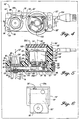
- FIGURES 4-6 illustrate a further embodiment of the present invention in the form of water jet blocker 10'.
- the components of the present invention shown in FIGURES 4-6 that correspond to those components shown in FIGURES 1A, 1B, and 2 are identified with the same part number but with the addition of prime (') designations. Also, the following description focuses on the differences between the embodiment shown in FIGURES 4-6 from that shown in FIGURES 1A, 1B, and 2, and thus not all aspects of the present invention shown in FIGURES 4-6 will be described in the same detail as described above with respect to FIGURES 1A, 1B, and 2.
- a flange connector 52 is used to attach a high pressure nozzle, not shown, to housing portion 16'.
- the connector 52 has a pair of diametrically opposed wing portions 54 having slots 56 formed therein for engaging screws 58 extending downwardly into the housing portion 16'. The heads of the screws bear against the upper surface of wing portions 54 to thereby securely hold the flange connector 52 locked in place.
- other methods could be used to attach the nozzle to the housing.
- a cup 62 snugly engages within a vertical bore formed through housing portion 16'.
- the cup 62 defines an interior cavity 19' through which the high speed water jet 12' enters and exits when not blocked.
- the cup 62 includes a cylindrical portion that extends vertically through the projecting portion 16'.
- the cup also includes an upper annular flange 64 having an upwardly open groove formed therein for receiving an O-ring 66 to form a water tight seal between the under side of the flange portion of connector 52 and cup 62.
- the cup 62 also includes a bottom floor 68 formed with a small diameter central opening 20 in alignment with the central vertical axis of the flange connector 52, which is in alignment with the center of the path of the water jet 12' entering the apparatus of the present invention.
- annular ring 72 extends downwardly from the under side of cup floor 68, with a counter bore 74 being formed therein of a size larger than the diameter of the central opening 70. Ring 72 serves as a drip guard to prevent moisture on the exterior of housing portion 16' from dripping into the path of travel of water jet 12' thereby interfering with or disrupting the flow of the water jet.
- a circular support and wear plate 76 fits within a shallow counter bore formed in the upper side of cup floor 68.
- An O-ring 78 is positioned within the counter bore to provide a seal with the under side of the wear plate 76, and also compensates for minor misalignments between the upper surface of the wear plate and the lower, flat surface 79 of the blocking bar 22' thereby to provide a substantially full face-to-face mating between the wear plate and the blocker bar lower surface.
- a small diameter central opening 80 is formed in the wear plate 23' through which the water jet 12' passes when in unblocked condition.
- cup 62 is composed of a hardware resistant non-corroding material, such as stainless steel.
- blocking bar 22' is supported for pivotal or toggle movement at a location intermediate its ends by a collar 24b' positioned within lateral passageway 24a'.
- the collar 24b' is generally triangularly shaped in cross-section, as shown in FIGURE 5.
- the collar 24b' is composed of a hard wear-resistant material, such as stainless steel.
- An O-ring seal 24c' is disposed within a groove extending around the inside diameter of the collar 24b' to seal against the outer diameter of the blocking bar 22'.
- the shape of the collar 24b' allows the blocking bar 22' to pivot freely side-to-side, and the O-ring seal 24c' allows the blocking bar to shift lengthwise, as discussed below.
- the distal end portion of the blocking bar 22' engages through an opening formed in the side wall of cup 62, thereby to extend into the interior of the cup.
- the portion of the blocking bar 22' engaged through a collar 24b' is formed with a circular exterior diameter
- the distal end portion of the blocking bar 24' is formed with a flattened lower surface to slidably mate with the flat upper surface of the wear plate 23', as discussed above.
- the proximal end portion of the blocking bar 22' is disposed within a lower cavity 25' formed in the lower portion of housing 18'.
- the proximal end of the blocking bar 22' is pivoted or toggled side-to-side by a pivot arm 28' pinned to the lower end of the output shaft 30' of rotary actuator 32'.
- the pivot arm 28' is formed with a pair of integral, downward extending, spaced apart lugs (corresponding to pins 26 shown in FIGURES 1 and 2) for receiving the proximal end of the blocking bar 22' therebetween.
- blocking bar 22' is pivoted side-to-side about collar 24b' as the pivot arm 28' rotates back and forth about axis 34', corresponding to the longitudinal center of output shaft 30'.
- the under side of the proximal end of the blocking bar 22' is also formed with the flat face corresponding to the distal end of the blocking bar 22'. This allows the blocking bar 22' to be removed and then repositioned end-to-end so that both end portions of the blocking bar can serve to block the water jet 12'.
- the surface of the blocking bar impacted by the water jet 12' is eroded away due to the extremely high pressure of the water jet.
- the longitudinal position of the blocking bar may be adjusted, thereby to present a different portion of the blocking bar to the high speed water jet 12' as the blocking bar is eroded under the action of the water jet,
- one end of the generally U-shaped, wire form connecting arm 82 extends through a close fitting hole extending transversely upwardly from the under side of the proximal end of the locking bar.
- a corresponding hole is formed in the opposite (distal) end of the blocking bar for use when the blocking bar is repositioned end-to-end, as described above.
- the longitudinal portion of the arm 82 rests against the upper surface of a bottom cap 39b' which closes off lower cavity 25'.
- the second transverse end portion of the arm 82 extends upwardly into an adjusting block 27' disposed within lower cavity 25'.
- the upper surface of the adjusting block 27' is disposed closely adjacent the bottom surface of the horizontal partition 84 that separates the lower cavity 25' from the housing upper cavity 33'.
- the adjusting bar 27' is formed with a threaded through hole for engaging the threaded portion of lead screw 29'.
- the lead screw 29' includes an enlarged circular knob 86 positioned outwardly of housing 18' for convenient manual rotation. The outer circumference of the knob 86 may be knurled to help grip the knob, especially when wet.
- a retaining clip 88 is locked onto the shaft of the lead screw at the base of the threads thereof to maintain the lead screw engaged through a close fitting horizontal bore hole formed in the housing 18'.
- a spring-loaded ball detent assembly 90 is snugly engaged within a blind bore formed in the wall of housing 18 at a location corresponding to the outer perimeter portion of lead screw knob 86.
- the detent assembly 90 includes a spring-loaded ball 92 which presses against the under side of the lead screw knob. Ideally, an indentation is formed in the lead screw knob to serve as a seat for the detent ball 92.
- the lead screw 29' is periodically rotated one revolution whereupon the lead screw seats with the detent ball 92, which retains the lead screw from rotating other than when desired.
- the connecting arm.82 conveniently advances and retracts the blocking bar 22' as the adjusting block 27' is advanced and retracted along the length of the lead screw 29', while at the same time permitting the proximal end portion of the blocking bar to pivot side-to-side under the control of pivot arm 28', To this end, the portion of the connecting arm 82 adjacent the proximal end of the blocking bar simply moves side-to-side with the movement of the blocking bar.
- the blocking bar 22' may be conveniently turned end-to-end by removing cap 39b' and then disengaging the connecting arm 82 from the blocking bar and the adjusting block 27', whereupon the blocking bar may be slidably removed from collar 24b'. After being rotated end-to-end, the blocking bar may be reinserted by reversing the above procedure.
- FIGURES 4-6 differs with the embodiment shown in FIGURES 1A, 1B, and 2 is the manner in which the deflected or blocked fluid from the water jet 12' is removed from the cavity 19', especially when the blocking bar 22' blocks the travel of the water jet.
- an air inlet port 38' is formed in the sloped upper ledge of the housing 18' located above and laterally to one side of lead screw 29'.
- a reduced diameter inlet passage 94 interconnects the inlet port 38' with an annular cavity 40' defined by the internal diameter of upper cavity 33' and the exterior of a heat conductive sleeve 43'.
- Such sleeve 43' is formed with upper and lower annular flanges, the outer perimeter of which snugly engages with the inside diameter of the upper cavity 33'.
- the gap between the upper and lower annular flanges and between the inside diameter of upper cavity 33' and the outer diameter of sleeve 43' defines the annular cavity 40'.
- an air outlet passageway 42' extends through housing 18' in a direction diametrically outwardly and downwardly from the cavity 40' to an elevation corresponding to the elevation of cavity 19' formed in housing portion 16'.
- the end of air outlet passageway 42' opposite annular cavity 40' intersects with a small diameter horizontal air passageway 96 which in turn exits into a larger diameter horizontal bore portion 98 that functions as a reduced pressure venturi chamber.
- the air flowing therethrough acts as a substantially free jet, unencumbered by the interior cylindrically shaped wall of the venturi chamber 98.
- FIGURES 1A, 1B, and 2 the embodiment of FIGURES 4-6 does not attempt to drive the overspray and blocked fluid out of counter bore cavity 19' under pressurized air, but rather effectively draws such overspray and blocked fluid out of the counter bore cavity under a reduced pressure of venturi action.
- the blocked water jet more quickly resumes a normal flow when unblocked, i.e., when the blocking bar 22' is removed from the path of travel of the water jet.
- the air entering housing portion 18' and exiting housing portion 16' also functions to cool the actuator 32' in the same manner as described above with respect to FIGURES 1A, 1B, and 2.
- a thermostat 102 is interposed between the electrical supply line 104 and the rotary actuator 32' to prevent electricity from reaching the rotary actuator if an overheated condition occurs.
Landscapes
- Life Sciences & Earth Sciences (AREA)
- Forests & Forestry (AREA)
- Engineering & Computer Science (AREA)
- Mechanical Engineering (AREA)
- Perforating, Stamping-Out Or Severing By Means Other Than Cutting (AREA)
- Nozzles (AREA)
- Jet Pumps And Other Pumps (AREA)
- Paper (AREA)
- Excavating Of Shafts Or Tunnels (AREA)
- Measuring Pulse, Heart Rate, Blood Pressure Or Blood Flow (AREA)
- Electrical Discharge Machining, Electrochemical Machining, And Combined Machining (AREA)
- Lasers (AREA)
- Flow Control (AREA)
- Centrifugal Separators (AREA)
Claims (9)
- Vorrichtung (10, 10') zum selektiven Unterbrechen des Stroms eines zum Schneiden verwendenden Hochdruckfluids, mit einem Sperrglied (22, 22'), einem Drehaktuator (32, 32'), der im Stande ist, ein Ausgangsmoment zu erzeugen, und einer Koppelanordnung mit Teilen zum Koppeln des Sperrglieds und des Drehaktuators, um das Dreh-Ausgangsmoment von dem Drehaktuator auf das Sperrglied zu übertragen und dieses hierdurch zu veranlassen, sich in den Strömungsweg des Hochdruckfluids zu schieben und so den Strom des Hochdruckfluids zu unterbrechen, und um es aus dem Strom des Hochdruckfluids herauszuschieben, um den Strom des Hochdruckstroms nicht zu unterbrechen, gekennzeichnet durch:(a) ein Gehäuse (18, 18') zum Haltern des Sperrglieds und des Drehaktuators, wobei das Sperrglied innerhalb des Gehäuses gehaltert ist und der Drehaktuator sich innerhalb des Gehäuses befindet;(b) eine Trägerstruktur (24b, 24b'), die das Sperrglied drehbar haltert, wobei die Trägerstruktur sich innerhalb des Gehäuses zwischen dem Strömungsweg des Hochdruckfluids und der Stelle der Koppeleinrichtung befindet, und wobei das Sperrglied um die Trägerstruktur schwenkbar ist;(c) wobei, wenn das Sperrglied sich in dem Strömungsweg des Hochdruckfluids befindet, der Strom auf das Sperrglied an einer von der Trägerstruktur entfernten Stelle auftrifft; und(d) Bereiche (44, 44') des Gehäuses so konfiguriert sind, daß sie den unterbrochenen Strom des Hochdruckfluids sammeln und den abgefangenen Strom des Hochdruckfluids zu einer entfernten Stelle leiten.
- Vorrichtung nach Anspruch 1, weiterhin umfassend eine Einrichtung zum Haltern des Sperrglieds gegen Aufschlagkräfte, denen es durch den Strom des Hochdruckfluids ausgesetzt ist.
- Vorrichtung nach Anspruch 1,
bei der, wenn das Sperrglied sich in dem Strömungsweg des Hochdruckfluids befindet, der Strom gegen das Sperrglied trifft, und
weiterhin umfassend ein Einstellsystem zum Einstellen der Stellung des Sperrglieds relativ zu dem Hochdruckstrom, um so die Stelle zu ändern, an der der Hochdruckstrom gegen das Sperrglied schlägt. - Vorrichtung nach Anspruch 1, bei der das Gehäuse einen Lufteinlaß, einen Luftauslaß und einen sich zwischen Lufteinlaß und Luftauslaß erstreckenden Kanal aufweist, wobei der Kanal mit der Stelle kommuniziert, an der das Sperrglied den Strömungsweg des Hochdruckfluids sperrt, die durch den Kanal strömende Luft in der Lage ist, das von dem Sperrglied abgefangene Hochdruckfluid von dem Sperrglied weg und in den Kanal und aus dem Luftauslaß heraus zu lenken.
- Vorrichtung nach Anspruch 4, bei der der Kanal außerdem Bereiche enthält, die durch eine wärmeleitende Hülse definiert werden, die das Äußere des Drehaktuators umgibt, wobei die Luft über Bereiche der wärmeleitenden Hülse strömt, um diese abzukühlen und auf diese Weise den Drehaktuator zu kühlen.
- Vorrichtung (10, 10') zum selektiven Unterbrechen des Stroms eines zum Schneiden verwendeten Hochdruckfluids, umfassend einen Drehaktuator (32, 32'), der ein Ausgangsdrehmoment erzeugen kann, ein Sperrglied (22, 22') und eine Koppelanordnung mit Bereichen, die auf das Sperrglied wirken und das Sperrglied mit dem Drehaktuator koppeln, um das Dreh-Ausgangsdrehmoment von dem Drehaktuator auf das Sperrglied zu übertragen und dieses zu drehen zwischen einer ersten Stellung innerhalb des Strömungswegs des Hochdruckfluids, um den Strom des Hochdruckfluids zu unterbrechen, und einer zweiten Stellung aus dem Weg des Hochdruckfluid-Stroms heraus, um den Strom des Hochdruckfluids nicht zu unterbrechen, gekennzeichnet durch:(a) ein Gehäuse (18, 18'), das relativ zu dem Weg des Hochdruckfluid-Stroms positionierbar ist und Bereiche aufweist, die den Drehaktuator und das Sperrglied haltern, wobei der Drehaktuator sich innerhalb des Gehäuses befindet; und(b) eine Trägerstruktur (24b, 24b') zum Drehlagern des Sperrglieds so, daß dieses um eine Achse dreht, welche sich zwischen der Stelle des Stroms des Hochdruckfluids und der Stelle der Kopplungsanordnung befindet, damit das Sperrglied um die Drehachse kippen kann.
- Vorrichtung nach Anspruch 6, bei der die Lagerungseinrichtung für das Sperrglied eine Justierung der Stelle des Sperrglieds innerhalb des Gehäuses ermöglicht, um denjenigen Bereich des Sperrglieds zu ändern, der den Strom des Hochdruckfluids unterbricht, wenn das Sperrglied sich in seiner ersten Stellung befindet.
- Vorrichtung nach Anspruch 6, bei der das Gehäuse außerdem einen Lufteinlaß und einen Luftkanal in Verbindung mit dem Lufteinlaß aufweist, um Luft von einer entfernten Luftquelle aufzunehmen, wobei der Luftkanal sich in Strömungsverbindung mit der Stelle befindet, an der der Strom des Hochdruckfluids von dem Sperrglied unterbrochen wird, um dadurch den unterbrochenen Strom des Hochdruckfluids von dieser Stelle wegzuführen.
- Vorrichtung nach Anspruch 6, bei der das Sperrglied einen Längsstab aufweist und die Lagerungseinrichtung den Längsstab so lagert, daß dieser um eine zwischen seinen Enden befindliche Achse dreht.
Priority Applications (1)
| Application Number | Priority Date | Filing Date | Title |
|---|---|---|---|
| EP01122900A EP1177867B1 (de) | 1996-03-19 | 1997-03-19 | Hochgeschwindigkeitssperrvorrichtung für einen Flüssigkeitsstrahl |
Applications Claiming Priority (2)
| Application Number | Priority Date | Filing Date | Title |
|---|---|---|---|
| US618319 | 1996-03-19 | ||
| US08/618,319 US5931178A (en) | 1996-03-19 | 1996-03-19 | High-speed water jet blocker |
Related Child Applications (1)
| Application Number | Title | Priority Date | Filing Date |
|---|---|---|---|
| EP01122900A Division EP1177867B1 (de) | 1996-03-19 | 1997-03-19 | Hochgeschwindigkeitssperrvorrichtung für einen Flüssigkeitsstrahl |
Publications (2)
| Publication Number | Publication Date |
|---|---|
| EP0796706A1 EP0796706A1 (de) | 1997-09-24 |
| EP0796706B1 true EP0796706B1 (de) | 2002-05-22 |
Family
ID=24477224
Family Applications (2)
| Application Number | Title | Priority Date | Filing Date |
|---|---|---|---|
| EP01122900A Expired - Lifetime EP1177867B1 (de) | 1996-03-19 | 1997-03-19 | Hochgeschwindigkeitssperrvorrichtung für einen Flüssigkeitsstrahl |
| EP97301849A Expired - Lifetime EP0796706B1 (de) | 1996-03-19 | 1997-03-19 | Hochgeschwindigkeitssperrvorrichtung für einen Flüssigkeitsstrahl |
Family Applications Before (1)
| Application Number | Title | Priority Date | Filing Date |
|---|---|---|---|
| EP01122900A Expired - Lifetime EP1177867B1 (de) | 1996-03-19 | 1997-03-19 | Hochgeschwindigkeitssperrvorrichtung für einen Flüssigkeitsstrahl |
Country Status (8)
| Country | Link |
|---|---|
| US (2) | US5931178A (de) |
| EP (2) | EP1177867B1 (de) |
| AT (1) | ATE217830T1 (de) |
| AU (1) | AU708012B2 (de) |
| CA (1) | CA2200378C (de) |
| DE (1) | DE69712666D1 (de) |
| NO (1) | NO309971B1 (de) |
| NZ (1) | NZ314443A (de) |
Families Citing this family (20)
| Publication number | Priority date | Publication date | Assignee | Title |
|---|---|---|---|---|
| EP1174034A1 (de) | 2000-07-19 | 2002-01-23 | Fmc | Verfahren zum Schneiden von Schweinebäuchen |
| GB2364894B8 (en) | 2000-07-19 | 2010-07-07 | Fmc Corp | Three axis portioning method |
| ES2166733B1 (es) * | 2000-09-28 | 2003-05-16 | Hipema Inversiones Sl | Maquina cortadora de vegetales y proceso de corte con ella obtenido. |
| NL1016346C2 (nl) * | 2000-10-06 | 2002-04-16 | Meijel B V Van | Snijinrichting. |
| US20030037817A1 (en) * | 2001-08-21 | 2003-02-27 | Fmc Technologies, Inc | High-speed water jet blocker |
| US6752373B1 (en) * | 2001-12-18 | 2004-06-22 | Fmc Technologies, Inc. | High-speed fluid jet blocker |
| US20040116831A1 (en) * | 2002-12-13 | 2004-06-17 | Scimed Life Systems, Inc. | Distal protection guidewire with nitinol core |
| US7097728B2 (en) * | 2003-09-25 | 2006-08-29 | Knauf Fiber Glass Gmbh | Frangible fiberglass insulation batts |
| US20080276777A1 (en) * | 2007-05-09 | 2008-11-13 | Fmc Technologies, Inc. | Water jet portioner |
| FR2925377B1 (fr) * | 2007-12-20 | 2009-12-25 | Airbus France | Dispositif de decoupage par jet d'eau avec dispositif ameliore de maintien des pieces |
| DE102010000478A1 (de) * | 2010-02-19 | 2011-08-25 | Hammelmann Maschinenfabrik GmbH, 59302 | Verfahren zur Funktionsunterbrechung eines Schneidstrahls sowie Vorrichtung zur Durchführung des Verfahrens |
| BR112012024259A2 (pt) * | 2010-03-25 | 2017-07-18 | Russell Mineral Equipment Pty Ltd | dispositivo de jato de água pulsante e pistola de água para a distribuição de pulsos de água de alta energia |
| EP2431128A1 (de) | 2010-09-17 | 2012-03-21 | Inflotek B.V. | Verfahren zur Herstellung eines formstabilen Filter- oder Siebeinsatzes |
| CA2935759A1 (en) | 2014-01-07 | 2015-07-16 | John Bean Technologies Corporation | High speed jet blocker with readily replaceable blocking material |
| EP3020520B1 (de) * | 2014-11-14 | 2018-01-03 | HP Scitex Ltd | Flüssigstickstoffstrahlstromverarbeitung von Papier, Kartons oder Pappe |
| CN108134983A (zh) * | 2016-11-30 | 2018-06-08 | 巨码科技股份有限公司 | 依速度提供适地性信息的方法与系统 |
| US10751902B2 (en) | 2017-11-28 | 2020-08-25 | John Bean Technologies Corporation | Portioner mist management assembly |
| LT6954B (lt) | 2021-03-25 | 2022-10-25 | Robotopia, UAB | Skysčio srovės formavimo ir išleidimo būdas ir įrenginiai šio būdo įgyvendinimui |
| LT6953B (lt) | 2021-03-25 | 2022-10-25 | Robotopia, UAB | Skysčio tiekimo būdas, išleidžiant ištisinę srovę, ir šio būdo įgyvendinimo sistema |
| CN118948385A (zh) * | 2024-04-01 | 2024-11-15 | 北京智愈医疗科技有限公司 | 一种快速消除水射流作用力的方法和装置 |
Family Cites Families (16)
| Publication number | Priority date | Publication date | Assignee | Title |
|---|---|---|---|---|
| US1831791A (en) * | 1930-03-28 | 1931-11-10 | Eastman Kodak Co | Camera shutter |
| US2408603A (en) * | 1940-05-28 | 1946-10-01 | Vickers Electrical Co Ltd | Mechanical relay of the fluid jet type |
| DE1808455A1 (de) * | 1967-11-13 | 1969-07-10 | Nat Res Dev | Durchdringung von Materialien mit Fluessigkeitsstrahlen |
| US3543798A (en) * | 1968-07-08 | 1970-12-01 | Singer General Precision | Pneumatically controlled servo valve |
| US3678746A (en) * | 1970-06-10 | 1972-07-25 | Sundstrand Data Control | Fluidic sensor for fluid stream velocity |
| CH570855A5 (de) * | 1973-06-12 | 1975-12-31 | Cerac Inst Sa | |
| US3934603A (en) * | 1974-01-08 | 1976-01-27 | General Electric Company | Fluidic upstream control of the directional flow of a power jet exiting a fluidic power nozzle |
| SE451163B (sv) * | 1983-06-13 | 1987-09-07 | Forenede Bryggerier As | Sett for detektering av fiskben med elektromagnetisk stralning varvid eventuell emitterad fluorescensstralning analyseras |
| US4603835A (en) * | 1983-11-09 | 1986-08-05 | The Perkin-Elmer Corporation | Shutter mechanism |
| GB2162050A (en) * | 1984-07-27 | 1986-01-29 | Gunsons Sortex Ltd | Method and apparatus for controlling the cutting of an object |
| DE3701673A1 (de) * | 1987-01-22 | 1988-08-04 | Juergen Dipl Ing Uehlin | Verfahren und vorrichtung zum schneiden von materialien mittels eines fluessigkeitsstrahles |
| JPS63218270A (ja) * | 1987-03-05 | 1988-09-12 | Hitachi Shonan Denshi Kk | 流体の間欠噴射ノズル装置 |
| US4920841A (en) * | 1988-12-29 | 1990-05-01 | General Dynamics Corporation | Energy dissipating receptacle |
| US4947589A (en) * | 1989-07-24 | 1990-08-14 | Truman's Inc., Ohio Corporation | Sandblasting valving device |
| SE469373B (sv) * | 1991-11-27 | 1993-06-28 | Lumetech As | En ventil foer vaetskestraalskaerning som utgoers av en i straalens vaeg in- och undanfoerbar skiva |
| FR2699850B1 (fr) * | 1992-12-30 | 1995-02-03 | Snecma | Dispositif d'arrêt de jet de liquide abrasif. |
-
1996
- 1996-03-19 US US08/618,319 patent/US5931178A/en not_active Expired - Lifetime
-
1997
- 1997-03-18 US US08/824,885 patent/US5927320A/en not_active Expired - Lifetime
- 1997-03-19 DE DE69712666T patent/DE69712666D1/de not_active Expired - Lifetime
- 1997-03-19 AT AT97301849T patent/ATE217830T1/de not_active IP Right Cessation
- 1997-03-19 AU AU16415/97A patent/AU708012B2/en not_active Ceased
- 1997-03-19 NO NO971289A patent/NO309971B1/no not_active IP Right Cessation
- 1997-03-19 EP EP01122900A patent/EP1177867B1/de not_active Expired - Lifetime
- 1997-03-19 CA CA002200378A patent/CA2200378C/en not_active Expired - Fee Related
- 1997-03-19 NZ NZ314443A patent/NZ314443A/xx unknown
- 1997-03-19 EP EP97301849A patent/EP0796706B1/de not_active Expired - Lifetime
Also Published As
| Publication number | Publication date |
|---|---|
| NO309971B1 (no) | 2001-04-30 |
| EP1177867A2 (de) | 2002-02-06 |
| AU708012B2 (en) | 1999-07-29 |
| NO971289D0 (no) | 1997-03-19 |
| NZ314443A (en) | 1999-02-25 |
| ATE217830T1 (de) | 2002-06-15 |
| EP1177867B1 (de) | 2005-11-23 |
| EP0796706A1 (de) | 1997-09-24 |
| AU1641597A (en) | 1997-09-25 |
| US5927320A (en) | 1999-07-27 |
| CA2200378A1 (en) | 1997-09-19 |
| DE69712666D1 (de) | 2002-06-27 |
| US5931178A (en) | 1999-08-03 |
| NO971289L (no) | 1997-09-22 |
| CA2200378C (en) | 2000-04-11 |
| EP1177867A3 (de) | 2002-03-06 |
Similar Documents
| Publication | Publication Date | Title |
|---|---|---|
| EP0796706B1 (de) | Hochgeschwindigkeitssperrvorrichtung für einen Flüssigkeitsstrahl | |
| JP3694318B2 (ja) | 要求に応じて昇華性粒子を生成し、噴射する装置 | |
| EP1165249B1 (de) | Verfahren und vorrichtung zur flüssigkeitsstrahl- formung | |
| JP4689909B2 (ja) | 切屑を切断する機械加工用の装置及びこのような装置のための切削工具 | |
| CN1243502C (zh) | 用于改进提取容纳在装料元件中的食品原料的方法和装置 | |
| PL120113B1 (en) | Apparatus for cooling a cutting tool of a mining cutter nta vrubnojj mashiny | |
| JPH03184800A (ja) | 超高圧水ツール | |
| RU2755456C1 (ru) | Устройство управления выпуском сжатой текучей среды | |
| US5248094A (en) | Adjustable fluid jet cleaner | |
| CN113276027A (zh) | 一种磨料射流的控制系统 | |
| CA2042046C (en) | Twin-jet process | |
| JP3686528B2 (ja) | 流体衝突装置 | |
| US5542873A (en) | Novel media valve | |
| EP2098322A1 (de) | Spülvorrichtung und -verfahren für eine elektrische Drahtentladungsmaschine | |
| US4659020A (en) | Quick adjustable shatter jet mechanism | |
| US5983763A (en) | Deflector mechanism for liquid-jet cutter | |
| US20030037817A1 (en) | High-speed water jet blocker | |
| US20080083307A1 (en) | Machine tool post having coolant distribution system | |
| KR880002159B1 (ko) | 액상감귤류 농축물에 사용하기 위한 음료분배방법 및 음료분배기 밸브조립장치 | |
| KR102368538B1 (ko) | 샤워기 헤드 | |
| JP2006102410A (ja) | 自動消火器 | |
| KR19990036229A (ko) | 실의 교락작업용 젯트(jet) | |
| KR940002158Y1 (ko) | 와이어 컷 방전 가공기의 작동유 플러싱 장치 | |
| KR200216364Y1 (ko) | 로 내 연와의 보수재 분사장치 | |
| CN117739615A (zh) | 刀具冷却装置、卷烟切割系统和刀具冷却方法 |
Legal Events
| Date | Code | Title | Description |
|---|---|---|---|
| PUAI | Public reference made under article 153(3) epc to a published international application that has entered the european phase |
Free format text: ORIGINAL CODE: 0009012 |
|
| 17P | Request for examination filed |
Effective date: 19970410 |
|
| AK | Designated contracting states |
Kind code of ref document: A1 Designated state(s): AT BE CH DE DK ES FI FR GB IT LI NL SE |
|
| 17Q | First examination report despatched |
Effective date: 20000922 |
|
| GRAG | Despatch of communication of intention to grant |
Free format text: ORIGINAL CODE: EPIDOS AGRA |
|
| GRAG | Despatch of communication of intention to grant |
Free format text: ORIGINAL CODE: EPIDOS AGRA |
|
| GRAH | Despatch of communication of intention to grant a patent |
Free format text: ORIGINAL CODE: EPIDOS IGRA |
|
| GRAH | Despatch of communication of intention to grant a patent |
Free format text: ORIGINAL CODE: EPIDOS IGRA |
|
| GRAA | (expected) grant |
Free format text: ORIGINAL CODE: 0009210 |
|
| PG25 | Lapsed in a contracting state [announced via postgrant information from national office to epo] |
Ref country code: NL Free format text: LAPSE BECAUSE OF FAILURE TO SUBMIT A TRANSLATION OF THE DESCRIPTION OR TO PAY THE FEE WITHIN THE PRESCRIBED TIME-LIMIT Effective date: 20020522 Ref country code: LI Free format text: LAPSE BECAUSE OF FAILURE TO SUBMIT A TRANSLATION OF THE DESCRIPTION OR TO PAY THE FEE WITHIN THE PRESCRIBED TIME-LIMIT Effective date: 20020522 Ref country code: IT Free format text: LAPSE BECAUSE OF FAILURE TO SUBMIT A TRANSLATION OF THE DESCRIPTION OR TO PAY THE FEE WITHIN THE PRESCRIBED TIME-LIMIT;WARNING: LAPSES OF ITALIAN PATENTS WITH EFFECTIVE DATE BEFORE 2007 MAY HAVE OCCURRED AT ANY TIME BEFORE 2007. THE CORRECT EFFECTIVE DATE MAY BE DIFFERENT FROM THE ONE RECORDED. Effective date: 20020522 Ref country code: FI Free format text: LAPSE BECAUSE OF FAILURE TO SUBMIT A TRANSLATION OF THE DESCRIPTION OR TO PAY THE FEE WITHIN THE PRESCRIBED TIME-LIMIT Effective date: 20020522 Ref country code: CH Free format text: LAPSE BECAUSE OF FAILURE TO SUBMIT A TRANSLATION OF THE DESCRIPTION OR TO PAY THE FEE WITHIN THE PRESCRIBED TIME-LIMIT Effective date: 20020522 Ref country code: BE Free format text: LAPSE BECAUSE OF FAILURE TO SUBMIT A TRANSLATION OF THE DESCRIPTION OR TO PAY THE FEE WITHIN THE PRESCRIBED TIME-LIMIT Effective date: 20020522 Ref country code: AT Free format text: LAPSE BECAUSE OF FAILURE TO SUBMIT A TRANSLATION OF THE DESCRIPTION OR TO PAY THE FEE WITHIN THE PRESCRIBED TIME-LIMIT Effective date: 20020522 |
|
| REF | Corresponds to: |
Ref document number: 217830 Country of ref document: AT Date of ref document: 20020615 Kind code of ref document: T |
|
| REG | Reference to a national code |
Ref country code: GB Ref legal event code: FG4D |
|
| REG | Reference to a national code |
Ref country code: CH Ref legal event code: EP |
|
| REF | Corresponds to: |
Ref document number: 69712666 Country of ref document: DE Date of ref document: 20020627 |
|
| PG25 | Lapsed in a contracting state [announced via postgrant information from national office to epo] |
Ref country code: SE Free format text: LAPSE BECAUSE OF FAILURE TO SUBMIT A TRANSLATION OF THE DESCRIPTION OR TO PAY THE FEE WITHIN THE PRESCRIBED TIME-LIMIT Effective date: 20020822 Ref country code: DK Free format text: LAPSE BECAUSE OF FAILURE TO SUBMIT A TRANSLATION OF THE DESCRIPTION OR TO PAY THE FEE WITHIN THE PRESCRIBED TIME-LIMIT Effective date: 20020822 |
|
| PG25 | Lapsed in a contracting state [announced via postgrant information from national office to epo] |
Ref country code: DE Free format text: LAPSE BECAUSE OF FAILURE TO SUBMIT A TRANSLATION OF THE DESCRIPTION OR TO PAY THE FEE WITHIN THE PRESCRIBED TIME-LIMIT Effective date: 20020823 |
|
| ET | Fr: translation filed | ||
| NLV1 | Nl: lapsed or annulled due to failure to fulfill the requirements of art. 29p and 29m of the patents act | ||
| PG25 | Lapsed in a contracting state [announced via postgrant information from national office to epo] |
Ref country code: ES Free format text: LAPSE BECAUSE OF FAILURE TO SUBMIT A TRANSLATION OF THE DESCRIPTION OR TO PAY THE FEE WITHIN THE PRESCRIBED TIME-LIMIT Effective date: 20021128 |
|
| REG | Reference to a national code |
Ref country code: CH Ref legal event code: PL |
|
| PLBE | No opposition filed within time limit |
Free format text: ORIGINAL CODE: 0009261 |
|
| STAA | Information on the status of an ep patent application or granted ep patent |
Free format text: STATUS: NO OPPOSITION FILED WITHIN TIME LIMIT |
|
| 26N | No opposition filed |
Effective date: 20030225 |
|
| PGFP | Annual fee paid to national office [announced via postgrant information from national office to epo] |
Ref country code: FR Payment date: 20070319 Year of fee payment: 11 |
|
| REG | Reference to a national code |
Ref country code: GB Ref legal event code: 732E |
|
| REG | Reference to a national code |
Ref country code: FR Ref legal event code: ST Effective date: 20081125 |
|
| PG25 | Lapsed in a contracting state [announced via postgrant information from national office to epo] |
Ref country code: FR Free format text: LAPSE BECAUSE OF NON-PAYMENT OF DUE FEES Effective date: 20080331 |
|
| REG | Reference to a national code |
Ref country code: GB Ref legal event code: 732E Free format text: REGISTERED BETWEEN 20090423 AND 20090429 |
|
| PGFP | Annual fee paid to national office [announced via postgrant information from national office to epo] |
Ref country code: GB Payment date: 20150318 Year of fee payment: 19 |
|
| GBPC | Gb: european patent ceased through non-payment of renewal fee |
Effective date: 20160319 |
|
| PG25 | Lapsed in a contracting state [announced via postgrant information from national office to epo] |
Ref country code: GB Free format text: LAPSE BECAUSE OF NON-PAYMENT OF DUE FEES Effective date: 20160319 |