EP0796134B1 - Procede de traitement du gaz naturel contenant de l'eau et des hydrocarbures condensables - Google Patents
Procede de traitement du gaz naturel contenant de l'eau et des hydrocarbures condensables Download PDFInfo
- Publication number
- EP0796134B1 EP0796134B1 EP96934889A EP96934889A EP0796134B1 EP 0796134 B1 EP0796134 B1 EP 0796134B1 EP 96934889 A EP96934889 A EP 96934889A EP 96934889 A EP96934889 A EP 96934889A EP 0796134 B1 EP0796134 B1 EP 0796134B1
- Authority
- EP
- European Patent Office
- Prior art keywords
- gas
- phase
- liquid
- solvent
- zone
- Prior art date
- Legal status (The legal status is an assumption and is not a legal conclusion. Google has not performed a legal analysis and makes no representation as to the accuracy of the status listed.)
- Expired - Lifetime
Links
Images


Classifications
-
- B—PERFORMING OPERATIONS; TRANSPORTING
- B01—PHYSICAL OR CHEMICAL PROCESSES OR APPARATUS IN GENERAL
- B01D—SEPARATION
- B01D53/00—Separation of gases or vapours; Recovering vapours of volatile solvents from gases; Chemical or biological purification of waste gases, e.g. engine exhaust gases, smoke, fumes, flue gases, aerosols
- B01D53/26—Drying gases or vapours
- B01D53/265—Drying gases or vapours by refrigeration (condensation)
-
- B—PERFORMING OPERATIONS; TRANSPORTING
- B01—PHYSICAL OR CHEMICAL PROCESSES OR APPARATUS IN GENERAL
- B01D—SEPARATION
- B01D53/00—Separation of gases or vapours; Recovering vapours of volatile solvents from gases; Chemical or biological purification of waste gases, e.g. engine exhaust gases, smoke, fumes, flue gases, aerosols
- B01D53/002—Separation of gases or vapours; Recovering vapours of volatile solvents from gases; Chemical or biological purification of waste gases, e.g. engine exhaust gases, smoke, fumes, flue gases, aerosols by condensation
-
- B—PERFORMING OPERATIONS; TRANSPORTING
- B01—PHYSICAL OR CHEMICAL PROCESSES OR APPARATUS IN GENERAL
- B01D—SEPARATION
- B01D53/00—Separation of gases or vapours; Recovering vapours of volatile solvents from gases; Chemical or biological purification of waste gases, e.g. engine exhaust gases, smoke, fumes, flue gases, aerosols
- B01D53/14—Separation of gases or vapours; Recovering vapours of volatile solvents from gases; Chemical or biological purification of waste gases, e.g. engine exhaust gases, smoke, fumes, flue gases, aerosols by absorption
- B01D53/1487—Removing organic compounds
-
- B—PERFORMING OPERATIONS; TRANSPORTING
- B01—PHYSICAL OR CHEMICAL PROCESSES OR APPARATUS IN GENERAL
- B01D—SEPARATION
- B01D53/00—Separation of gases or vapours; Recovering vapours of volatile solvents from gases; Chemical or biological purification of waste gases, e.g. engine exhaust gases, smoke, fumes, flue gases, aerosols
- B01D53/26—Drying gases or vapours
- B01D53/263—Drying gases or vapours by absorption
-
- C—CHEMISTRY; METALLURGY
- C10—PETROLEUM, GAS OR COKE INDUSTRIES; TECHNICAL GASES CONTAINING CARBON MONOXIDE; FUELS; LUBRICANTS; PEAT
- C10G—CRACKING HYDROCARBON OILS; PRODUCTION OF LIQUID HYDROCARBON MIXTURES, e.g. BY DESTRUCTIVE HYDROGENATION, OLIGOMERISATION, POLYMERISATION; RECOVERY OF HYDROCARBON OILS FROM OIL-SHALE, OIL-SAND, OR GASES; REFINING MIXTURES MAINLY CONSISTING OF HYDROCARBONS; REFORMING OF NAPHTHA; MINERAL WAXES
- C10G2300/00—Aspects relating to hydrocarbon processing covered by groups C10G1/00 - C10G99/00
- C10G2300/10—Feedstock materials
- C10G2300/1025—Natural gas
Definitions
- the subject of the present invention is a method for treating a gas, in particular a dehydration process.
- the present invention advantageously finds its application for the dehydration of natural gas.
- one of the main constituents to be eliminated is water which proves to be a hydrate promoter and which promotes corrosion.
- the hydrates can cause blockage and blockage of transport lines which prevent in the long run any passage of gas, and the corrosive action of gas a deterioration of pipes and treatment facilities.
- the patent FR-A-2,605,241 and the document EP-A-0 362 023 describe a natural gas treatment process using several steps carried out in several successive devices.
- the gas to be treated is contacted in a first enclosure with a refrigerated physical solvent to produce a gas saturated with water added with the solvent, this gas is then cooled in an exchanger causing the condensation of an aqueous phase containing the solvent and the water saturation as well as a phase of liquid hydrocarbons. Dehydrated gas and cooled, and the fraction of condensed hydrocarbons are then separated in a separation enclosure.
- the present invention overcomes the drawbacks of the prior art and allows to treat gases containing water which may be present at a lower cost different forms and which must be dehydrated, in particular natural gas. She also applies to the treatment of gases produced in installations industrial, for example refinery gas.
- the process and installation according to the invention requires only one enclosure to carry out the dehydration, for example a column exchanger, which makes the installation less expensive and less bulky than the known installations of the prior art.
- natural gas comprising at least water, methane and condensable hydrocarbons, such as C 3 + and / or possibly C 2 +.
- C 3 + denotes the set of hydrocarbons comprising at least three carbon atoms per molecule
- treated gas means the dehydrated gas or at least partially purified from saturation water.
- the liquid containing the solvent can be introduced into the upper part of the contact area.
- natural gas can flow against liquid flow.
- step b) it is possible to cool by producing a temperature gradient varying according to the nature of said gas and / or the nature of said solvent.
- the solvent is chosen from the group comprising: methylpropyl ether, ethylpropylether, dipropylether, methyltertiobutylether, dimethoxymethane, dimethoxyethane, methanol, ethanol, methoxyethanol, propanol, amines and ketones.
- the contact zone may include a reboiler.
- the first and the second hydrocarbon phase can be introduced into a means of stabilization.
- the method according to the invention is used to dehydrate a natural gas comprising water and at least one hydrocarbon other than methane and at least partial separation of hydrocarbons other than methane.
- the process used leads to a reduction in treatment costs natural gas and an increase in the production yield of fractions of selected hydrocarbons.
- the method used according to the invention consists in carrying out simultaneously the refrigeration of a gas comprising saturation water and, its brought into contact with a liquid fraction, in the presence of a solvent having in particular the function of avoiding the formation of ice and / or hydrates.
- the refrigeration step causes the saturation water to condense contained in the gas as well as liquid fractions of hydrocarbons in the case rich natural gas.
- these two stages are, for example, carried out in a single enclosure comprising at least one circuit for bringing the gas, the liquid and solvent fraction or, main circuit and, a refrigeration circuit.
- the installation advantageously allows fractionate and recover liquid hydrocarbons for compositions different, depending on the composition of the gas treated and the demand for producer.
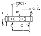
- Figure 1 illustrates the basic principle of the process applied as example of a natural gas saturated with water and containing hydrocarbons associated superiors.
- the gas to be treated is introduced into an enclosure EC 1, such as a heat exchanger, through the conduit 2 located in its lower part. Inside this exchanger EC 1, it is simultaneously contacted with a liquid phase formed at least in part by a solvent arriving via line 3 in the exchanger EC 1 , and cooled by an indirect heat exchange, for example at through a wall ( Figures 8, 9).
- Refrigeration can be ensured by a heat transfer fluid, which penetrates into the shell of the exchanger EC 1 by the conduit 4, circulates from top to bottom to lower the temperature of the gas to be treated which circulates in the ascending direction, before emerging from the exchanger via line 5.
- the gas to be treated is preferably contacted against the current and continuously with the liquid phase comprising the solvent flowing in a downward direction inside the exchanger EC 1 and the gas to be treated in an upward direction. Refrigeration of the gas is preferably ensured by a continuous heat exchange against the current.
- This refrigeration causes condensation of heavy hydrocarbons contained in the gas and part of the gas saturation water.
- These two condensed liquid phases flow down the device by gravity, against the flow of the treated gas which gradually loses its propane, butane and heavier hydrocarbons due to material exchange between the gas phase and the liquid hydrocarbons.
- the liquid phase condensed hydrocarbon is enriched progressively with heavier constituents coming down.
- the condensed aqueous phase rich in solvent at the top of the exchanger loses solvent by contact with the gas.
- the treated gas loaded with solvent is evacuated at the head of the column exchanger EC 1 through line 6.
- the solvent-laden gas phase and the condensed liquid phase are then treated, for example, separately according to their use or their mode of transport, or specifications given by the producer or consumer.
- the solvent vaporized and entrained in the gas phase makes it possible to avoid hydrate formation problems related to refrigeration.
- the heat exchanger EC 1 can also be equipped with means 9 for controlling the temperature, for example temperature sensors which are connected to control and treatment means 10.
- the temperature sensors can be distributed along the 'heat exchanger EC 1 so as to measure at several points the temperatures prevailing along the path of the gas in circulation.
- the gas to be treated can be precooled before being introduced into the exchanger EC 1 , using an available refrigeration fluid, such as water and / or air in an exchanger E 1 located on the conduit 2.
- This first precooling step makes it possible in particular to separate a gasoline fraction formed by the condensable hydrocarbons under the temperature and pressure conditions established at the outlet of the exchanger E 1 .
- a solvent at least partially miscible with water is used. Of preferably it has a lower boiling point than water or forms with water an azeotrope with a boiling point below that of water so that it can be entrained by uncondensed gas.
- This solvent is for example an alcohol and preferably methanol. he can also be chosen from the following solvents: methylpropyl ether, ethylpropylether, dipropylether, methyltertiobutylether, dimethoxymethane, dimethoxyethane, methanol, ethanol, methoxyethanol, propanol or even be chosen from different classes of solvents such as for example amines or ketones or still a mixture formed from one or more of these products.
- the amount of solvent to be injected is usually adjusted according to the temperature, pressure and / or composition of the gas in order to avoid formation of hydrates and the formation of ice crystals due to the presence of the water.
- the ratio in moles of the flow of solvent to the flow of treated gas is between 1/1000 and 1/10.
- the treatment process is optimized by adapting the quantity of solvent injected as a function, for example of the gas composition and / or operating conditions, such as temperature and / or variation of temperature and / or pressure.
- the quantity of solvent injected as a function, for example of the gas composition and / or operating conditions, such as temperature and / or variation of temperature and / or pressure.
- account is also taken of the operations then carried out on the treated gas from the enclosure.
- the gas By flow against the current, the gas entrains the solvent contained in the liquid phases which descend by gravity. These liquid phases are collected in bottom, substantially free of solvent.
- the solvent injected at the head is therefore mainly evacuated in the gas phase leaving the head. The quantity of solvent injected can thus be adjusted in order to obtain the concentration level in this gas phase required to avoid the formation of hydrates, taking into account temperature and pressure conditions.
- the solvent content in the gas phase is generally reduced and the lower the lower the temperature.
- the amount of solvent injected at the top, for example, of the exchanger is therefore relatively small and constitutes a make-up intended to compensate for losses in the gas.
- the solvent injected at the head is not necessarily pure and can be, for example example, mixed with water, provided however that the concentration of solvent in aqueous phase makes it possible to avoid the formation of hydrates.
- the temperature variation or the temperature gradient caused in the exchanger are for example chosen according to the nature of the gas and, quantity of condensed hydrocarbons, such as LPG and gasoline, to be recovered.
- the reduction in temperature of the gas to be treated is preferably produced to obtain a temperature gradient over the entire exchanger.
- the process is partially or entirely self-refrigerated, that is to say that the refrigeration is ensured at least in part by the treated gas.
- FIG. 2A shows schematically an alternative embodiment in which the heat exchanger EC 1 is provided with a refrigeration circuit using an external heat transfer fluid, entering through the conduit 4 and leaving through the conduit 5 described in Figure 1, the conduits 4 and 5 being located in its upper part and an additional refrigeration circuit provided by at least part of the treated gas discharged from the exchanger through the conduit 6, entering the exchanger through a conduit 11 located, preferably below the discharge pipe 5 of the heat transfer fluid, and emerging through a pipe 6 'at the bottom of the exchanger.
- the external heat transfer fluid at least partially cools the treated gas in the upper part of the exchanger, which leaves the exchanger via line 6 and which is reintroduced into the exchanger through the conduit 11, which extends the conduit 6.
- a liquid fraction is discharged which mainly contains the heaviest constituents contained in the gas which feeds the heat exchanger EC 1 , and condensed during the process.
- This liquid fraction can be stabilized by heating the liquid volume collected at the bottom of the enclosure of the exchanger EC 1 according to the diagram shown in FIG. 2B, which integrates in the lower part of the exchanger a stabilization means, such as a reboiler B 1 . There is thus collected via line 8 a liquid fraction already stabilized and the production yield of C 1 -C 2 is improved, the methane and ethane vaporized by heating being found in the treated gas discharged through line 6 '.
- a first example of implementation of the basic method described in relation to FIG. 2A makes it possible to obtain from a natural gas containing associated higher hydrocarbons, a dehydrated gas largely depleted in constituents containing at least three carbon atoms.
- the heat exchanger EC 1 is, for example a tubular exchanger-column, the tubes contain a lining to increase the transfer of material between the gas, the aqueous phase, the hydrocarbon phase and the solvent.
- the mass composition of natural gas is for example the following: WATER 82.30 METHANOL 0.00 NITROGEN 211.97 CARBON DIOXIDE 397.79 METHANE 25765.00 ETHANE 6028.62 PROPANE 4360.50 Isobutane 1335.05 BUTANE 487.21 ISOPENTANE 668.81 PENTANE 528.87 HEXANE 1053.47 TOTAL KG / HR 42919.59
- Natural gas is for example previously cooled in the exchanger E1 at a temperature greater than or equal to its dew temperature close to 43 ° C, and at a pressure substantially equal to 4.4 MPa, before being injected into the treatment device via line 2 with a flow rate substantially equal to 42919 Kg / h.
- the solvent mainly composed of methanol, is injected through the pipe 3 at a temperature less than or equal to ambient temperature and, by example, close to -20 ° C, with a flow rate substantially equal to 13 Kg / h.
- the refrigeration in the column exchanger EC 1 is ensured, for example in its upper part by a heat transfer fluid which penetrates by the conduit 4 at a temperature close to -27 ° C. and which is evacuated by the conduit 5 at a temperature close to -23 ° C.
- the lower part of the exchanger EC 1 is cooled by the treated gas evacuated by the conduit 6, and reintroduced into the exchanger by the conduit 11 at a temperature substantially equal to - 22 ° C and with a pressure close to 4.4 MPa.
- the treated and recycled gas lowers the temperature of the gas to be treated flowing against the current, by heat exchange before being evacuated through line 6 'at a temperature of 39 ° C.
- the natural gas to be treated while gradually cooling becomes depleted on the one hand, into hydrocarbons containing more than three carbon atoms which condense to form a liquid phase formed by liquid hydrocarbons, and on the other hand in water, the aqueous phase formed by condensation of the water of saturation being evacuated by gravity as it forms.
- the water from the exchanger EC 1 is recovered from the condensation water of the treated gas containing less than 100 ppm mass of solvent. This water is discharged through line 7 at a temperature of 43 ° C with a flow rate close to 82.0 kg / h.
- the liquid hydrocarbon phase enriched in C 3 + hydrocarbons and containing for example more than 99% of C 5 + hydrocarbons, 65% of the C 4 + compounds and 12% of C 3 + is evacuated via line 8 after separation of the phase aqueous, for example by decantation, with a flow rate of approximately 5175 Kg / h.
- the treated gas, dehydrated and depleted of about 50% of C 3 + hydrocarbons is evacuated via line 6, with a flow rate of 37,710 kg / h.
- the production yield of C 1 and C 2 is around 98%, while in a process according to the prior art the yield is around 92%.
- the installation is self-refrigerated in using part of the treated gas from line 6 as a refrigerant.
- FIG. 3 Such a case is illustrated by the exemplary embodiment shown diagrammatically in FIG. 3.
- the treated gas leaving the head of the exchanger is cooled in a device 12 disposed on the duct 6, for example by expansion through a valve or by expansion through a turbine.
- the gas thus cooled is reinjected, via line 4, into the exchanger EC 1 , in which it lowers the temperature of the gas to be treated flowing in the ascending direction by heat exchange. It comes out, after heat exchange, through line 6 'before being sent to another treatment installation and / or to a transport line.
- the installation makes it possible to recover the cuts of hydrocarbons heavier than methane contained in a natural gas in function in particular of their composition, in particular the number of atoms of carbon per molecule.
- FIG. 4 describes a treatment installation integrating means of recovery of the LPG fractions of a natural gas, distinct from the means of recovery of gasoline.
- Figure 4 differs from that shown in FIG. 2 because it includes recovery means (14, 15) arranged at exchanger level.
- This embodiment can also, without departing from the scope of the invention, be combined with the devices shown in Figures 1 and 3.
- Natural gas contains hydrocarbons which condense at different temperatures.
- the lowering of the temperature according to a gradient given in the exchanger allows to condense in different zones the different fractions of hydrocarbons contained in natural gas. Fractions the heaviest are collected at the bottom of the exchanger and the most light at the head of the exchanger. It is also possible to recover in an area intermediate, a hydrocarbon fraction corresponding to an interval of boiling point set.
- the exchanger EC 1 is equipped with a means of recovery, such as a plate 14 communicating with the main circuit for bringing the treated gas and the solvent into contact.
- the recovery plate 14 is located in a part of the exchanger, the level of which is fixed for example as a function of the nature of the cuts or hydrocarbons to be recovered and of the temperature prevailing at different places in the column.
- the plate 14 makes it possible to separate the condensed aqueous phase from the condensed hydrocarbons containing mainly propane and butanes as well as a small amount of methane and ethane and recover them for then evacuate them at least in part by a lateral duct 15.
- the exchanger can be equipped with several plates recovery connected to lateral evacuation pipes, distributed along the exchanger according to the nature of the hydrocarbons to be recovered.
- the plate 14 is equipped with at least one conduit 144 allowing the injection of a liquid phase, for example an aqueous phase containing a solvent.
- the liquid phase injected through line 144 can come, for example a step of washing a withdrawn liquid fraction, such as, for example, the fraction of liquid hydrocarbons withdrawn through line 15. Indeed, at the level of plateau 14 this fraction of liquid hydrocarbons is in equilibrium with a aqueous phase partly containing solvent and gas phase containing also solvent. Due to this balance, the liquid hydrocarbons withdrawn via line 15 contain traces of solvent.
- the aqueous phase coming from the washing step and containing the solvent initially dissolved in the liquid hydrocarbon fraction, is recycled in the column exchanger EC 1 by the conduit 144, then it is brought into contact against the current with the gas to be treated . During this contact, it gives up, by material transfer, the amount of solvent which is entrained in the gas phase.
- the liquid phase reinjection line containing solvent to recovery can also be positioned at other levels of the column exchanger. It is also possible to equip the column exchanger with several injection lines of this type depending on the desired treatments.
- gases other than natural gases for example example, to refinery gases.
- a second example of implementation of the invention described in relation to FIG. 4 makes it possible to selectively recover the hydrocarbon cuts contained in natural gas according to a desired composition, for example associated hydrocarbons containing more than three carbon atoms.
- Natural gas is cooled and contacted according to the process described for example at Figure 3.
- the other modes described in Figures 1 and 2 can also apply without departing from the scope of the invention.
- natural gas depletes in heavy C 3 + constituents by yielding by condensation at least in part the constituents formed from molecules with at least three carbon atoms and by forming a liquid hydrocarbon phase which is enriched with up and down in heavier and heavier constituents.
- the propane concentration in the liquid hydrocarbon phase obtained at the sixth plate is, for example, close to 26% mass while it is of 9.8% in the liquid hydrocarbon phase discharged at the bottom of the equipment through line 8.
- the propane concentration changes throughout the column exchanger it is desirable and advantageous to take off the hydrocarbon phases formed according to levels corresponding to the compositions sought.
- Natural gas is introduced via line 2 with a flow rate of 42,837 Kg / h, with a temperature close to 43 ° C, and at a pressure substantially equal to 4.5 MPa.
- the amount of methanol injected through line 3 is, for example 13.9 Kg / h to maintain a methanol concentration gradient in the phase aqueous formed in the exchanger corresponding to a concentration varying from 99% mass at the top of the exchanger at a temperature of -23 ° C and at a concentration of 0.01% mass at the bottom of the exchanger for a temperature about 43 ° C.
- the aqueous phase and the hydrocarbon phase comprising the majority of the constituents having carbon atoms greater than C 4 + are removed after decantation through the conduits 7 and 8.
- the liquid hydrocarbon phase comprising in particular C 5 + hydrocarbons, which is discharged through line 8 with a flow rate of 2525 Kg / h, contains more than 75% of the C 5 + hydrocarbons contained in the gas to be treated.
- the natural gas treated and cooled by expansion in the device 12 ensures by heat exchange, the refrigeration of the natural gas to be treated circulating against the current, before being evacuated, after exchange, by the conduit 6 'with a flow rate of 36,715 kg / h. It is dehydrated and depleted by more than 55% of C 3 + hydrocarbons.
- a hydrocarbon phase enriched with 65% in compounds C 3 and C 4 is recovered at the level of the plate 14, while the hydrocarbon phase discharged through line 8 is only enriched by approximately 20% in C 3 and C 4 .
- the installation makes it possible to stabilize the hydrocarbon fractions recovered according to one of the processes described in relation in Figures 1 to 4.
- FIGS 5 and 6 respectively describe installations comprising a dehydration device provided with hydrocarbon stabilization means condensed (LPG and gasoline).
- the evacuation conduit 15 communicating with the tray recovery 14 of condensed LPG in Figure 4 is connected to a device 16 allowing their stabilization.
- the device used is, for example, a device for stabilization known to those skilled in the art which will therefore not be described.
- the device used for stabilization comprises for example an exchanger as described above allowing perform a heat exchange and a material exchange simultaneously, which will be described later in FIGS. 8 and 9.
- the stabilization process complementary to the recovery of fractions of hydrocarbons consists in sending the stabilization device 16 the fraction of condensate recovered from the plate 14 and comprising methane and ethane in small quantities and a majority of condensed LPG.
- the fraction rich in methane and ethane is evacuated from the stabilization device 16 by a conduit 17 and recycled to the exchanger EC 1 at the level of the plate 14 to be recovered and mixed with the gas to be treated.
- the stabilized LPG fraction comes out in the lower part of the stabilization at the reboiler 19 by a conduit 18.
- Such a procedure advantageously makes it possible to stabilize the LPG before their recovery by the producer and on the other hand to increase the methane and ethane yield of the process.
- the installation described in FIG. 5 comprises a second stabilization device 21 for stabilizing the gasoline discharged by the conduit 8.
- the operating diagram is identical to that described in relation to FIG. 5, the condensate discharged through line 8 comprising mainly gasoline and a small quantity of C 1 to C 4 hydrocarbons is sent to the stabilization device 21.
- the stabilized portion of gasoline is evacuated through line 22 at the level of the reboiler 23.
- the gas fraction composed mainly of methane, ethane and propane, is evacuated from the device via line 25 to be recycled and remixed with the gas to be treated arriving via line 2.
- FIG. 7 differs from that of FIG. 6 by the addition of two expansion valves V 1 and V 2 located respectively on the evacuation conduits 14 and 8.
- the gas fractions coming from the stabilization devices 16 and 21 are recompressed through means such as compressors K 1 and K 2 before being returned by a pipe 28 to the gas to be treated at the pipe 2.
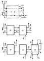
- FIGS 8 and 9 describe alternative embodiments of the device according to the invention where the stabilization of a liquid fraction is carried out in a contact and heat exchange zone, such as that described previously.
- the liquid fraction originating from zone Z 1 can be stabilized in a contact and exchange zone Z 3 as shown in the figure 8.
- the gas to be treated arrives via the conduit 50 in the contact and exchange zone Z 1 .
- a gaseous phase enriched in solvent is collected at the head of this contact and heat exchange zone Z 1 , which is sent to the contact and exchange zone Z 2 and which emerges through the conduit 52 at the head of this zone of contact Z 2 .
- a relatively light liquid fraction is collected, which is discharged through line 53.
- a solvent is sent via line 100, for example to avoid the formation of hydrates, this solvent being mainly evacuated in the gas leaving via line 52.
- zone Z 1 in the case of two contact and exchange zones Z 1 , Z 2 , the liquid fraction coming from zone Z 1 can be stabilized in zone Z 2 as shown in the diagram in FIG. 9.
- the liquid fraction from zone Z 2 is sent to zone Z 1 in which it circulates against the current with the vapor phase generated by heating in this zone Z 1 .
- This heat exchange also contributes to the cooling of the gas arriving via line 50.
- the stabilized liquid fraction is evacuated through line 60.
- the vapor fraction resulting from this stabilization step is evacuated at the head of zone Z1 and sent at 61 to the zone Z 2 .
- Liquid fractions from one of the contact and exchange zones can also be stabilized in a contact area and heat exchange operating at a higher temperature, after expansion to facilitate the stabilization operation.
- the vapor fractions from such a stabilization step must in this case be recompressed before being sent to a contact area and superior exchange.
- the method according to the invention thus makes it possible to separate, fractionate and to stabilize the condensable fractions contained in a gas to be treated.
- the exchanger EC 1 is for example an exchanger of the tube and shell type such as that which is shown diagrammatically in FIG. 10.
- the gas to be treated arriving via line 2 circulates in an ascending direction at the interior of vertical tubes 30.
- These tubes are preferably provided with a packing, for example a structured packing making it possible to improve the contact between the rising gas and the falling liquid fractions.
- the treated gas is evacuated at the head via line 6.
- the solvent is introduced via line 3 and sent in the various tubes 30 by a supply ramp 31 to a plate of distribution 32.
- the liquid hydrocarbon phase stabilized by heating using a reboiler B 2 located in the lower part of the exchanger EC 1 , for example, is discharged under level control, via line 8, and the aqueous phase is evacuated under level control via line 7.
- Refrigeration is ensured by a heat transfer fluid introduced into the exchanger through line 33 and removed after heat exchange through line 34.
- the exchanger EC 1 is a plate exchanger, for example of brazed aluminum, such as that which is shown diagrammatically in FIG. 11.
- Such an exchanger consists of an assembly of flat plates 35 between which there are corrugated intermediate plates 36 which allow mechanically maintain the assembly and improve heat transfer.
- These plates delimit channels 37 in which the fluids circulate participating in the heat exchange process.
- the gas to be treated introduced into the exchanger through line 2 circulates in the channels 37 in an upward direction being cooled progressively by the heat transfer fluid.
- the corrugated interlayers 36 playing the role of a structured packing, favor the contact between the rising gas and the fractions liquids going down.
- the solvent sent through line 3 is distributed uniformly above the channels 37 in which the gas to be treated circulates.
- the dehydrated gas is evacuated in exchanger head via line 6, cooled by expansion, according to a process by example described in Figure 3 and reintroduced at the top of the exchanger through the conduit 38 which arrives substantially perpendicular to the plane of the section shown in FIG. 11 in a supply enclosure for channels not shown in the figure. It is evacuated after heat exchange by the conduit 39 which emerges perpendicular to the plane of the section shown in the Figure 11, the conduit being connected to an evacuation enclosure of the channels not shown in the figure.
- the supply and discharge chambers are devices known to those skilled in the art allowing the passage of fluids flowing in each of the channels in the exhaust pipe and vice versa distribute the fluid coming from a conduit in the different channels.
- the liquid hydrocarbon phase possibly stabilized by the reboiler B 3 , is discharged under level control (LC, V) through line 8 and the aqueous phase is evacuated under level control through line 7.
- level control LC, V
- plate heat exchangers can also be used, for example example of exchangers with stainless steel plates welded together, i.e. edge to edge, either over their entire surface for example by a welding technique by broadcast.
- the plates are, for example, formed by explosion or engraved chemically.
- Figure 12 shows schematically an embodiment of a tray allowing to take phases according to their nature according to a process described in the Figure 4, for example.
- the tray has chimneys 40 allowing the gas to rise towards the upper part of the exchanger.
- the liquid phase which is collected on this tray can be evacuated through line 15 with a controlled flow, but can also flow by overflow towards the lower part of the exchanger. he it is thus possible to collect only a fraction of the liquid phase arriving from the upper part of the exchanger.
- liquid phases for example one liquid hydrocarbon phase and an aqueous phase
- the heavier aqueous phase tends to accumulate at the bottom of the tray and it is possible to evacuate it for example to through perforations 41 arranged in the tray.
Landscapes
- Chemical & Material Sciences (AREA)
- Engineering & Computer Science (AREA)
- Analytical Chemistry (AREA)
- General Chemical & Material Sciences (AREA)
- Oil, Petroleum & Natural Gas (AREA)
- Chemical Kinetics & Catalysis (AREA)
- Physics & Mathematics (AREA)
- Thermal Sciences (AREA)
- Production Of Liquid Hydrocarbon Mixture For Refining Petroleum (AREA)
- Separation By Low-Temperature Treatments (AREA)
- Organic Low-Molecular-Weight Compounds And Preparation Thereof (AREA)
- Gas Separation By Absorption (AREA)
- Treating Waste Gases (AREA)
Applications Claiming Priority (3)
| Application Number | Priority Date | Filing Date | Title |
|---|---|---|---|
| FR9512004A FR2739789B1 (fr) | 1995-10-11 | 1995-10-11 | Procede et dispositif de traitement d'un gaz contenant de l'eau tel qu'un gaz naturel |
| FR9512004 | 1995-10-11 | ||
| PCT/FR1996/001581 WO1997013574A1 (fr) | 1995-10-11 | 1996-10-10 | Procede et dispositif de traitement du gaz naturel contenant de l'eau et des hydrocarbures condensables |
Publications (2)
| Publication Number | Publication Date |
|---|---|
| EP0796134A1 EP0796134A1 (fr) | 1997-09-24 |
| EP0796134B1 true EP0796134B1 (fr) | 2002-07-17 |
Family
ID=9483482
Family Applications (1)
| Application Number | Title | Priority Date | Filing Date |
|---|---|---|---|
| EP96934889A Expired - Lifetime EP0796134B1 (fr) | 1995-10-11 | 1996-10-10 | Procede de traitement du gaz naturel contenant de l'eau et des hydrocarbures condensables |
Country Status (8)
| Country | Link |
|---|---|
| US (1) | US5907924A (no) |
| EP (1) | EP0796134B1 (no) |
| JP (1) | JPH10511043A (no) |
| CA (1) | CA2207983C (no) |
| DE (1) | DE69622370D1 (no) |
| FR (1) | FR2739789B1 (no) |
| NO (1) | NO316360B1 (no) |
| WO (1) | WO1997013574A1 (no) |
Cited By (2)
| Publication number | Priority date | Publication date | Assignee | Title |
|---|---|---|---|---|
| FR2925954A1 (fr) * | 2007-12-27 | 2009-07-03 | Armines Ass Pour La Rech Et Le | Systeme de refroidissement d'un melange psychrometrique par couplage d'une unite de condensation et d'une unite d'evaporation |
| CN110833736A (zh) * | 2019-11-26 | 2020-02-25 | 江西晶昊盐化有限公司 | 一种并联预处理式两级湿法除尘方法及其应用 |
Families Citing this family (20)
| Publication number | Priority date | Publication date | Assignee | Title |
|---|---|---|---|---|
| FR2771020B1 (fr) * | 1997-11-19 | 1999-12-31 | Inst Francais Du Petrole | Dispositif et methode de traitement d'un fluide par compression diphasique et fractionnement |
| US7384637B2 (en) * | 2000-01-31 | 2008-06-10 | Immunitor Usa Inc. | Drug for AIDS treatment |
| FR2822838B1 (fr) * | 2001-03-29 | 2005-02-04 | Inst Francais Du Petrole | Procede de deshydratation et de fractionnement d'un gaz naturel basse pression |
| FR2822839B1 (fr) * | 2001-03-29 | 2003-05-16 | Inst Francais Du Petrole | Procede ameliore des deshydratation et de degazolinage d'un gaz naturel humide |
| RO121819B1 (ro) * | 2003-10-01 | 2008-05-30 | Petru Baciu | Procedeu şi instalaţie pentru colectarea gazului metan liber, de pe fundul mării |
| AU2006325211B2 (en) * | 2005-12-16 | 2010-02-18 | Shell Internationale Research Maatschappij B.V. | Process for cooling down a hot flue gas stream |
| DE102008017525B3 (de) * | 2008-04-04 | 2009-01-29 | Uhde Gmbh | Vorrichtung und Verfahren zur Abscheidung von Prozesskondensat bei der Dampfreformierung |
| FR2939694B1 (fr) * | 2008-12-16 | 2010-12-17 | Inst Francais Du Petrole | Procede de deshydratation partielle d'un gaz par absorption sur un solvant regenerable par demixtion a temperature ambiante |
| US8899557B2 (en) | 2011-03-16 | 2014-12-02 | Exxonmobil Upstream Research Company | In-line device for gas-liquid contacting, and gas processing facility employing co-current contactors |
| CN104936674B (zh) | 2013-01-25 | 2016-11-09 | 埃克森美孚上游研究公司 | 气体料流与液体料流的接触 |
| AR096132A1 (es) | 2013-05-09 | 2015-12-09 | Exxonmobil Upstream Res Co | Separar dióxido de carbono y sulfuro de hidrógeno de un flujo de gas natural con sistemas de co-corriente en contacto |
| AR096078A1 (es) | 2013-05-09 | 2015-12-02 | Exxonmobil Upstream Res Co | Separación de impurezas de una corriente de gas usando un sistema de contacto en equicorriente orientado verticalmente |
| JP5739486B2 (ja) * | 2013-07-26 | 2015-06-24 | 株式会社神戸製鋼所 | 分離方法及び分離装置 |
| SG11201704529RA (en) | 2015-01-09 | 2017-07-28 | Exxonmobil Upstream Res Co | Separating impurities from a fluid steam using multiple co-current contactors |
| AU2016220515B2 (en) | 2015-02-17 | 2019-02-28 | Exxonmobil Upstream Research Company | Inner surface features for co-current contactors |
| EP3268119A1 (en) | 2015-03-13 | 2018-01-17 | ExxonMobil Upstream Research Company | Coalescer for co-current contactors |
| JP6931405B2 (ja) | 2017-06-15 | 2021-09-01 | エクソンモービル アップストリーム リサーチ カンパニー | バンドル式コンパクト並流接触システムを使用する分別システム |
| MX2019014327A (es) | 2017-06-15 | 2020-02-05 | Exxonmobil Upstream Res Co | Sistema de fraccionamiento que usa sistemas compactos de contacto de co-corriente. |
| BR112019026673A2 (pt) | 2017-06-20 | 2020-06-30 | Exxonmobil Upstream Research Company | sistemas e métodos de contato compactos para coletar compostos contendo enxofre |
| AU2018322436B2 (en) | 2017-08-21 | 2021-07-22 | Exxonmobil Upstream Research Company | Integration of cold solvent and acid gas removal |
Family Cites Families (14)
| Publication number | Priority date | Publication date | Assignee | Title |
|---|---|---|---|---|
| US3253390A (en) * | 1963-07-29 | 1966-05-31 | Phillips Petroleum Co | Dehydration of gases and regeneration of desiccant |
| DE1669328C3 (de) * | 1967-04-15 | 1974-07-25 | Linde Ag, 6200 Wiesbaden | Verfahren zum Entfernen von sauren Komponenten aus Erdgas |
| US3589104A (en) * | 1969-06-26 | 1971-06-29 | Dow Chemical Co | Recovery of chemicals from off-gases |
| US3633338A (en) * | 1970-03-06 | 1972-01-11 | Phillips Petroleum Co | Gas method and apparatus for drying |
| GB2026534B (en) * | 1978-07-17 | 1983-01-19 | Dut Pty Ltd | Simultaneuos cooling and removal of water from hydrocarbon gas mixtures |
| US4460385A (en) * | 1982-11-26 | 1984-07-17 | Exxon Research And Engineering Co. | Process for the removal of acid gases from hydrocarbon gases containing the same |
| FR2544998B1 (fr) * | 1983-04-29 | 1985-07-19 | Inst Francais Du Petrole | Nouveau procede de fractionnement d'un melange gazeux de plusieurs constituants |
| FR2550956B1 (fr) * | 1983-08-26 | 1985-10-25 | Petroles Cie Francaise | Procede de purification d'un gaz naturel, pouvant notamment etre integre dans un procede de liquefaction de ce gaz naturel |
| DE3533595A1 (de) * | 1985-09-20 | 1987-04-02 | Nitsche Manfred | Verfahren zum abscheiden von wasserdampf, loesungsmitteln und/oder schadstoffen aus einem gasstrom und vorrichtung zur durchfuehrung des verfahrens |
| AT385914B (de) * | 1985-11-26 | 1988-06-10 | Innofinance Altalanos Innovaci | Verfahren und einrichtung zur entfeuchtung gasfoermiger medien |
| FR2636857B1 (fr) * | 1988-09-26 | 1990-12-14 | Inst Francais Du Petrole | Procede de deshydratation, de desacidification et de separation d'un condensat d'un gaz naturel |
| WO1991005030A1 (en) * | 1989-09-29 | 1991-04-18 | Productcontrol Limited | Method and apparatus for refinement or treatment of material |
| FI100506B (fi) * | 1991-10-16 | 1997-12-31 | Kh Innovations Oy | Selektiiviseen absorptioon perustuva erotus- ja väkevöintimenetelmä |
| FR2733162B1 (fr) * | 1995-04-19 | 1997-06-06 | Inst Francais Du Petrole | Procede et dispositif d'elimination d'au moins un gaz acide par solvant pour l'epuration du gaz naturel |
-
1995
- 1995-10-11 FR FR9512004A patent/FR2739789B1/fr not_active Expired - Fee Related
-
1996
- 1996-10-10 DE DE69622370T patent/DE69622370D1/de not_active Expired - Lifetime
- 1996-10-10 JP JP9514774A patent/JPH10511043A/ja not_active Ceased
- 1996-10-10 US US08/849,665 patent/US5907924A/en not_active Expired - Lifetime
- 1996-10-10 EP EP96934889A patent/EP0796134B1/fr not_active Expired - Lifetime
- 1996-10-10 WO PCT/FR1996/001581 patent/WO1997013574A1/fr active IP Right Grant
- 1996-10-10 CA CA002207983A patent/CA2207983C/fr not_active Expired - Fee Related
-
1997
- 1997-06-10 NO NO19972665A patent/NO316360B1/no not_active IP Right Cessation
Cited By (3)
| Publication number | Priority date | Publication date | Assignee | Title |
|---|---|---|---|---|
| FR2925954A1 (fr) * | 2007-12-27 | 2009-07-03 | Armines Ass Pour La Rech Et Le | Systeme de refroidissement d'un melange psychrometrique par couplage d'une unite de condensation et d'une unite d'evaporation |
| WO2009083696A3 (fr) * | 2007-12-27 | 2009-08-27 | Association Pour La Recherche Et Le Developpement Des Methodes Et Processus Industriels "Armines" | Systeme de refroidissement d'un melange psychrometrique par couplage d'une unite de condensation et d'une unite d'evaporation |
| CN110833736A (zh) * | 2019-11-26 | 2020-02-25 | 江西晶昊盐化有限公司 | 一种并联预处理式两级湿法除尘方法及其应用 |
Also Published As
| Publication number | Publication date |
|---|---|
| CA2207983C (fr) | 2005-09-27 |
| NO972665D0 (no) | 1997-06-10 |
| NO972665L (no) | 1997-08-08 |
| DE69622370D1 (de) | 2002-08-22 |
| FR2739789A1 (fr) | 1997-04-18 |
| WO1997013574A1 (fr) | 1997-04-17 |
| EP0796134A1 (fr) | 1997-09-24 |
| NO316360B1 (no) | 2004-01-19 |
| JPH10511043A (ja) | 1998-10-27 |
| FR2739789B1 (fr) | 1997-11-21 |
| US5907924A (en) | 1999-06-01 |
| CA2207983A1 (fr) | 1997-04-17 |
Similar Documents
| Publication | Publication Date | Title |
|---|---|---|
| EP0796134B1 (fr) | Procede de traitement du gaz naturel contenant de l'eau et des hydrocarbures condensables | |
| EP0768502B1 (fr) | Procédé et dispositif de liquéfaction et de traitement d'un gaz naturel | |
| EP0848982B1 (fr) | Procédé et dispositif de traitement d'un gaz par refrigeration et mise en contact avec un solvant | |
| EP0596800B1 (fr) | Procédé et dispositif de déshydrogénation catalytique d'une charge paraffinique C2+ comprenant des moyens pour inhiber l'eau dans l'effluent | |
| EP0783031B1 (fr) | Procédé de déshydratation, de désacidification et de dégazolinage d'un gaz naturel, utilisant un mélange de solvants | |
| CA2034806C (fr) | Procede et dispositif pour le transport et le traitement d'un gaz naturel | |
| FR2814379A1 (fr) | Procede de desacidification d'un gaz par absorption dans un solvant avec un controle de la temperature | |
| CA2230092C (fr) | Procede de desacidification avec production de gaz acides en phase liquide | |
| FR2822838A1 (fr) | Procede de deshydratation et de fractionnement d'un gaz naturel basse pression | |
| EP0770667A1 (fr) | Procédé de séchage de gaz au glycol incluant la purification des rejets gazeux | |
| FR2771022A1 (fr) | Procede de desacidification d'un gaz a tres forte teneur en gaz acides | |
| EP0768106B1 (fr) | Procédé de fractionnement d'un fluide contenant plusieurs constituants séparables, tel qu'un gaz naturel | |
| FR2822839A1 (fr) | Procede ameliore des deshydratation et de degazolinage d'un gaz naturel humide | |
| EP3643394B1 (fr) | Procédé de déshydratation d'un gaz hydrocarbone | |
| EP0528709B2 (fr) | Procédé de séparation d'un mélange de gaz par absorption | |
| EP0835921B1 (fr) | Procédé de déshydratation et de dégazolinage d'un gaz, comportant un étage de refroidissement préliminaire | |
| EP0605322B1 (fr) | Procédé de déshydratation et/ou dessalage et de fractionnement simultané d'un effluent de gisement pétrolier | |
| EP0530062B1 (fr) | Procédé de fractionnement d'huile et de gaz sur un effluent de gisement pétrolier | |
| OA10141A (fr) | Procédé de stabilisation des pétroles bruts bruts à la sortie du puits d'extraction et son dispositif de mise en oeuvre | |
| WO2018087471A1 (fr) | Procédé de séparation cryogénique d'un courant de gaz naturel | |
| FR2874218A1 (fr) | Procede pour la recuperation d'un gaz riche en hydrogene et d'un liquide stabilise | |
| FR3058509A3 (fr) | Vaporiseur-condenseur a bain pour un procede de separation cryogenique d'un courant de gaz naturel | |
| BE582906A (no) |
Legal Events
| Date | Code | Title | Description |
|---|---|---|---|
| PUAI | Public reference made under article 153(3) epc to a published international application that has entered the european phase |
Free format text: ORIGINAL CODE: 0009012 |
|
| AK | Designated contracting states |
Kind code of ref document: A1 Designated state(s): DE DK FR GB IT |
|
| 17P | Request for examination filed |
Effective date: 19971017 |
|
| 17Q | First examination report despatched |
Effective date: 20010123 |
|
| GRAG | Despatch of communication of intention to grant |
Free format text: ORIGINAL CODE: EPIDOS AGRA |
|
| GRAG | Despatch of communication of intention to grant |
Free format text: ORIGINAL CODE: EPIDOS AGRA |
|
| RTI1 | Title (correction) |
Free format text: METHOD FOR TREATING NATURAL GAS CONTAINING WATER AND CONDENSIBLE HYDROCARBONS |
|
| GRAG | Despatch of communication of intention to grant |
Free format text: ORIGINAL CODE: EPIDOS AGRA |
|
| GRAH | Despatch of communication of intention to grant a patent |
Free format text: ORIGINAL CODE: EPIDOS IGRA |
|
| RTI1 | Title (correction) |
Free format text: METHOD FOR TREATING NATURAL GAS CONTAINING WATER AND CONDENSIBLE HYDROCARBONS |
|
| GRAH | Despatch of communication of intention to grant a patent |
Free format text: ORIGINAL CODE: EPIDOS IGRA |
|
| GRAA | (expected) grant |
Free format text: ORIGINAL CODE: 0009210 |
|
| AK | Designated contracting states |
Kind code of ref document: B1 Designated state(s): DE DK FR GB IT |
|
| PG25 | Lapsed in a contracting state [announced via postgrant information from national office to epo] |
Ref country code: IT Free format text: LAPSE BECAUSE OF FAILURE TO SUBMIT A TRANSLATION OF THE DESCRIPTION OR TO PAY THE FEE WITHIN THE PRESCRIBED TIME-LIMIT;WARNING: LAPSES OF ITALIAN PATENTS WITH EFFECTIVE DATE BEFORE 2007 MAY HAVE OCCURRED AT ANY TIME BEFORE 2007. THE CORRECT EFFECTIVE DATE MAY BE DIFFERENT FROM THE ONE RECORDED. Effective date: 20020717 |
|
| REG | Reference to a national code |
Ref country code: GB Ref legal event code: FG4D Free format text: NOT ENGLISH |
|
| GBT | Gb: translation of ep patent filed (gb section 77(6)(a)/1977) |
Effective date: 20020717 |
|
| REF | Corresponds to: |
Ref document number: 69622370 Country of ref document: DE Date of ref document: 20020822 |
|
| PG25 | Lapsed in a contracting state [announced via postgrant information from national office to epo] |
Ref country code: DK Free format text: LAPSE BECAUSE OF FAILURE TO SUBMIT A TRANSLATION OF THE DESCRIPTION OR TO PAY THE FEE WITHIN THE PRESCRIBED TIME-LIMIT Effective date: 20021017 |
|
| PG25 | Lapsed in a contracting state [announced via postgrant information from national office to epo] |
Ref country code: DE Free format text: LAPSE BECAUSE OF FAILURE TO SUBMIT A TRANSLATION OF THE DESCRIPTION OR TO PAY THE FEE WITHIN THE PRESCRIBED TIME-LIMIT Effective date: 20021018 |
|
| PLBE | No opposition filed within time limit |
Free format text: ORIGINAL CODE: 0009261 |
|
| STAA | Information on the status of an ep patent application or granted ep patent |
Free format text: STATUS: NO OPPOSITION FILED WITHIN TIME LIMIT |
|
| 26N | No opposition filed |
Effective date: 20030422 |
|
| REG | Reference to a national code |
Ref country code: FR Ref legal event code: CD |
|
| PGFP | Annual fee paid to national office [announced via postgrant information from national office to epo] |
Ref country code: FR Payment date: 20101103 Year of fee payment: 15 |
|
| PGFP | Annual fee paid to national office [announced via postgrant information from national office to epo] |
Ref country code: GB Payment date: 20101025 Year of fee payment: 15 |
|
| GBPC | Gb: european patent ceased through non-payment of renewal fee |
Effective date: 20111010 |
|
| REG | Reference to a national code |
Ref country code: FR Ref legal event code: ST Effective date: 20120629 |
|
| PG25 | Lapsed in a contracting state [announced via postgrant information from national office to epo] |
Ref country code: FR Free format text: LAPSE BECAUSE OF NON-PAYMENT OF DUE FEES Effective date: 20111102 Ref country code: GB Free format text: LAPSE BECAUSE OF NON-PAYMENT OF DUE FEES Effective date: 20111010 |