EP0795705B1 - Regelhahn und Abdichtungsmechanismus - Google Patents
Regelhahn und Abdichtungsmechanismus Download PDFInfo
- Publication number
- EP0795705B1 EP0795705B1 EP97301583A EP97301583A EP0795705B1 EP 0795705 B1 EP0795705 B1 EP 0795705B1 EP 97301583 A EP97301583 A EP 97301583A EP 97301583 A EP97301583 A EP 97301583A EP 0795705 B1 EP0795705 B1 EP 0795705B1
- Authority
- EP
- European Patent Office
- Prior art keywords
- seal
- port
- rotor
- flange
- rim
- Prior art date
- Legal status (The legal status is an assumption and is not a legal conclusion. Google has not performed a legal analysis and makes no representation as to the accuracy of the status listed.)
- Expired - Lifetime
Links
Images

Classifications
-
- F—MECHANICAL ENGINEERING; LIGHTING; HEATING; WEAPONS; BLASTING
- F16—ENGINEERING ELEMENTS AND UNITS; GENERAL MEASURES FOR PRODUCING AND MAINTAINING EFFECTIVE FUNCTIONING OF MACHINES OR INSTALLATIONS; THERMAL INSULATION IN GENERAL
- F16K—VALVES; TAPS; COCKS; ACTUATING-FLOATS; DEVICES FOR VENTING OR AERATING
- F16K11/00—Multiple-way valves, e.g. mixing valves; Pipe fittings incorporating such valves
- F16K11/02—Multiple-way valves, e.g. mixing valves; Pipe fittings incorporating such valves with all movable sealing faces moving as one unit
- F16K11/08—Multiple-way valves, e.g. mixing valves; Pipe fittings incorporating such valves with all movable sealing faces moving as one unit comprising only taps or cocks
- F16K11/085—Multiple-way valves, e.g. mixing valves; Pipe fittings incorporating such valves with all movable sealing faces moving as one unit comprising only taps or cocks with cylindrical plug
- F16K11/0856—Multiple-way valves, e.g. mixing valves; Pipe fittings incorporating such valves with all movable sealing faces moving as one unit comprising only taps or cocks with cylindrical plug having all the connecting conduits situated in more than one plane perpendicular to the axis of the plug
Definitions
- the present invention is directed to a rotary control valve which may be used in connection with a water conditioning system, and in particular to a control valve having a rotor located within a housing and a seal mechanism for creating a seal between ports of the housing and ports of the rotor.
- a seal mechanism including a seal member for use in a valve having a housing with one or more ports located in an internal surface and having a rotor with an external surface and one or more ports located in the external surface, the rotor being selectively rotatable within the housing.
- Such a seal mechanism is referred to below as a seal mechanism of the type described; and it is an object of this invention to provide an improvement in such a seal mechanism.
- a seal mechanism of the type described is characterised in that the seal member includes a web, a first aperture located in the web, a first flange extending from the web in a first direction and a second flange extending from the web in a second direction generally opposite to the first direction, the flanges extending along the web around the first aperture, the first flange having a first sealing face adapted to sealingly engage the housing, the second flange having a second sealing face adapted to sealingly engage the external surface of the rotor, the seal member being adapted to provide a sealed fluid passage through the first aperture between a port of the rotor and a port of the housing.
- the invention also extends to a valve for controlling the flow of fluid through a water conditioning system and comprising a plurality of said seal mechanisms as above defined.
- Other features of the invention are defined in the appended claims.
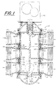
- Figure 1 is a cross-sectional view of one embodiment of the rotary control valve and seal mechanism of the present invention.
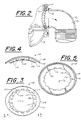
- Figure 2 is a partial cross-sectional view of the rotary control valve.
- Figure 3 is an external side elevational view of the seal retainer of the seal mechanism.
- Figure 4 is a bottom view of the seal mechanism.
- Figure 5 is an external side elevational view of the seal member of the seal mechanism.
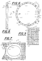
- Figure 6 is a top plan view of the cage of the seal mechanism.
- Figure 7 is a cross-sectional view of the cage taken along lines 7-7 of Figure 6.
- Figure 8 is a cross-sectional view of the cage taken along lines 8-8 of Figure 6.
- Figure 9 is a partial side elevational view of the cage taken along lines 9-9 of Figure 6.
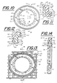
- Figure 10 is an external side elevational view of the seal and retainer assembly of the seal mechanism.
- Figure 11 is a cross-sectional view of the seal and retainer assembly taken along lines 11-11 of Figure 10.
- Figure 12 is a cross-sectional view of the seal and retainer assembly taken along lines 12-12 of Figure 10.
- Figure 13 is partial side elevational view of the seal mechanism showing the seal and retainer assembly in engagement with the cage.
- Figure 14 is a cross-sectional view taken along lines 14-14 of Figure 13.
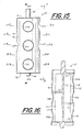
- Figure 15 is a front elevational view of the rotor of the control valve.
- Figure 16 is a cross-sectional view of the rotor taken along lines 16-16 of Figure 15.
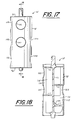
- Figure 17 is a side elevational view of the rotor taken along lines 17-17 of Figure 15.
- Figure 18 is a cross-sectional view of the rotor taken along lines 18-18 of Figure 17.
- Figure 19 is a cross-sectional view of the rotor taken along lines 19-19 of Figure 15.
- Figure 20 is a cross-sectional view of the rotor taken along lines 20-20 of Figure 15.
- Figure 21 is a cross-sectional view of the rotor taken along lines 21-21 of Figure 15.
- Figure 22 is a cross-sectional view of the rotor taken along lines 22-22 of Figure 15.
- Figure 23 is a cross-sectional view of the rotor taken along lines 23-23 of Figure 15.
- FIG. 1 A preferred embodiment of the rotary control valve 20 and of the seal mechanism 22 of the present invention is shown in Figure 1.
- the control valve 20 is adapted for use in controlling the operation of a liquid conditioning system, such as a water filtration system.
- the control valve 20, as shown in Figure 1, includes a housing 24, a rotor 26 and one or more seal mechanisms 22.
- the housing 24 includes a central body member 30 having a side wall 32 which forms a generally cylindrical chamber 34 within the housing 24.
- the housing 24 also includes a first end cap 36 which is removably attached to a first end of the central body member 30 and a second end cap 38 which is removably attached to the second and opposite end of the central body member 30.
- the end caps 36 and 38 enclose the ends of the chamber 34 in the housing 24.
- the first end cap 36 includes a bearing member 40 and the second end cap 38 includes a bearing member 42 and a passageway which extends through the second end cap 38.
- the side wall 32 of the housing 24 includes an inlet a first port 46 in fluid communication with the chamber 34 which is adapted to be placed in fluid communication with a first fluid conduit 48 having a fluid passage 49.
- the first fluid conduit 48 is connected to an external plumbing system which provides a supply of raw or untreated liquid.
- the side wall 32 includes a second port 50 in fluid communication with the chamber 34 which is located diametrically across the chamber 34 from the first port 46.
- the second port 50 is adapted to be placed in fluid communication with a second fluid conduit 52 having a fluid passage 54 which contains treated liquid.
- a third port 56 is located in the side wall 32 in fluid communication with the chamber 34.
- the third port 56 is adapted to be connected in fluid communication with a third fluid conduit 58 having a third fluid passage 60 which provides fluid communication with a first port of a mineral tank (not shown), which is preferably in fluid communication with the top of the mineral tank.
- a fourth port 62 is located in the side wall 32 of the housing 24 in fluid communication with the chamber 34.
- the fourth port 62 is adapted to be connected in fluid communication with a fourth fluid conduit 64 having a fourth fluid passage 66.
- the fourth fluid passage 66 is adapted to be connected to a second port of the mineral tank, which is preferably in fluid communication with the bottom of the mineral tank.
- the fourth port 62 is located diametrically across the chamber 34 from the third port 56.
- the side wall 32 of the housing 24 includes a fifth port 68 which is in fluid communication with the chamber 34.
- the fifth port 68 is adapted to be connected in fluid communication with a fifth fluid conduit 70 having a fifth fluid passage 72.
- the fifth fluid passage 72 is adapted to provide fluid communication with a backwash drain.
- the side wall 32 of the housing 24 includes a sixth port 74 which is in fluid communication with the chamber 34.
- the sixth port 74 is adapted to be placed in fluid communication with a sixth fluid conduit 76 having a sixth fluid passage 78.
- the sixth fluid passage 78 is adapted to provide a supply of treated liquid.
- the sixth port 74 is located diametrically across the chamber 34 from the fifth port 68.
- the side wall 32 of the housing 24 also includes a seventh port 80, as best shown in Figure 2, which is in fluid communication with the chamber 34.
- the seventh port 80 is adapted to be placed in fluid communication with a seventh fluid conduit 82 having a seventh fluid passage 84.
- the seventh fluid passage 84 is adapted to provide fluid communication with a rapid rinse drain.
- the seventh port 80 is disposed in the side wall 32 at an approximate angle of 90° to the ports 68 and 74.
- the ports 46, 56 and 68 are aligned with one another in a generally longitudinal direction.
- the ports 50, 62 and 74 are also aligned with one another in a generally longitudinal direction.
- the rotor 26 includes a generally tubular and cylindrical side wall 90 having an external cylindrical surface 92.
- the side wall 90 extends between a first end 94 and a second end 96.
- the rotor 26 includes a cylindrical shaft 98 which is adapted to be rotatably located within the bearing member 42 of the housing 24 and a cylindrical shaft 100 which is adapted to be rotatably located within the bearing member 40 of the housing 24.
- the rotor 26 includes a central axis 102 which extends concentrically within the side wall 90 and through the shafts 98 and 100.
- the rotor 26 is selectively rotatable about the axis 102 in either a clockwise or a counterclockwise direction.
- the shaft 98 of the rotor 26 is adapted to be connected to a control mechanism 104 which controls the selective rotation of the rotor 26 to any of a plurality of rotational positions as desired.
- the side wall 90 of the rotor 26 includes a port 110A, a port 110B, and a port 110C.
- the ports 110A-C are aligned in a longitudinal direction generally parallel to the axis 102.
- the port 110A is located in an upper portion of the rotor 26
- the port 110B is located in a central portion of the rotor 26
- the port 110C is located in a lower portion of the rotor 26.
- the side wall 90 of the rotor 26 includes a port 110D which is disposed at an approximately 90° angle to the port 110B about the axis 102.
- the port 110D is located in the center portion of the rotor 26 approximately midway between the first and second ends 94 and 96 of the side wall 90.
- the side wall 90 of the rotor 26 includes a port 110E and a port 110F.
- the port 110E is located in the upper portion of the rotor 26 and the port 110F is located in the center portion of the rotor 26.
- the ports 110E and 110F are longitudinally aligned with one another in a direction generally parallel to the axis 102 and are respectively disposed at an approximately 90° angle to the ports 110A and 110B about the axis 102.
- the side wall 90 of the rotor 26 also includes a port 110G and a port 110H.
- the port 110G is located in the center portion of the rotor 26 and the port 110H is located in the lower portion of the rotor 26.
- the ports 110G and 110H are longitudinally aligned with one another in a direction generally parallel to the axis 102 and are respectively located diametrically across the chamber 34 from the ports 110B and 110C.
- the rotor 26 includes a plurality of longitudinal walls 112 which extend generally radially from the central axis 102 to the side wall 90.
- the rotor 26 also includes a plurality of transverse walls 114 which extend between selected longitudinal walls 112 and the side wall 90.
- the walls 112 and 114 form a plurality of chambers within the rotor 26.
- the rotor 26 includes a chamber 116 which forms a fluid passage 118 through the rotor 26 between the ports 110A and 110B.
- the rotor 26 also includes a chamber 120 which forms a fluid passage 122 between the ports 110G and 110H.
- the rotor 26 includes a chamber 124 which forms a fluid passage 126 between the ports 110E and 110F.
- the rotor 26 also includes a chamber 128 which forms a fluid passage 130 between the ports 110D and 110C.
- the seal mechanism 22 includes a seal cage 136, a seal member 138 and a seal retainer 140.
- the seal cage 136 includes a generally cylindrical collar 142 and a spacer member 144.
- the collar 142 includes an upper generally circular rim 146 and a spaced apart and parallel lower generally circular rim 148.
- the collar 142 extends in a generally circular manner from a first end 150 to a spaced apart second end 152.
- the ends 150 and 152 are each generally linear and extend at an angle relative to one another such that a generally V-shaped gap is formed between the ends 150 and 152.
- Each end 150 and 152 of the collar 142 includes an elongate channel 154.
- the spacer member 144 is a generally V-shaped wedge.
- the spacer member 144 includes a flange 156 on each side thereof which is adapted to be slidably inserted within a respective channel 154.
- the collar 142 is formed from a plastic material and includes a plurality of longitudinal and transverse ribs. The collar 142 is sized to fit closely within the chamber 34 along the side wall 32 of the housing 24. The spacer member 144 is inserted between the ends 150 and 152 of the collar 142 and wedges the seal mechanism 22 into engagement with the side wall 32 as the spacer member 144 is slid downwardly between the ends 150 and 152.
- the upper rim 146 of the collar 142 includes a plurality of pockets 158 and the lower rim 148 includes a plurality of pegs 160.
- One or more seal cages 136 are adapted to be stacked one on top of the other such that the pegs in an upper seal cage fit within the pockets of the lower and adjacent seal cage.
- the control valve 20 includes three seal cages 136 stacked one on top of the other.
- the seal cage 136 as shown in Figures 6 and 7 includes three ports 162A-C.
- Each port 162A-C includes a rim 163.
- a groove 164 having a wall 166 extends around the circumference of each port 162A-C.
- the groove 164 is located in the external surface of the collar 142.
- a first seal cage 136 is adapted to be positioned as the bottom seal cage within the chamber 34, as shown in Figure 1, such that the port 162A is in fluid communication with the port 68, the port 162B is in fluid communication with the port 80 and the port 162C is in fluid communication with the port 74.
- a second seal cage 136 is used as the center seal cage within the chamber 34, as shown in Figure 1, such that the port 162A is in fluid communication with the port 56 and the port 162C is in fluid communication with the port 62, and the port 162B is unused.
- a third seal cage 136 is used as the top seal cage within the chamber 34, as shown in Figure 1, such that the port 162A is in fluid communication with the port 46 and the port 162C is in fluid communication with the port 50, while the port 162B is unused. While the seal cage 136 as shown in Figures 6 and 7 includes three ports, the seal cage may include fewer or additional ports as desired.
- the seal member 138 is generally elliptical.
- the seal member 138 includes a generally elliptical-shaped web 170 which forms a generally elliptical-shaped aperture 172 which extends through the seal member 138.
- the web 170 includes an internal rim 174 which includes a plurality of inwardly extending teeth 176 and an external rim 178.
- the web 170 includes an internal surface 180 and an external surface 182.
- the seal member 138 also includes an external flange 184 which extends outwardly from the external surface 182 of the web 170.
- the external flange 184 extends around the circumference of the web 170 along the external rim 178.
- the external flange 184 includes an external sealing face 186 which includes an internal seal rib 188 and an external seal rib 190.
- the external sealing face 186 and ribs 188 and 190 are adapted to sealingly engage the internal surface of the side wall 32 of the housing member 24.
- the seal member 138 also includes an internal flange 192 which extends inwardly from the internal surface 180 of the web 170 towards the axis 102.
- the internal flange 192 is located at and extends around the web 170 along the internal rim 174 such that the internal flange 192 is offset from the external flange 184.
- the internal flange 192 includes an internal sealing face 194.
- the internal sealing face 194 includes an internal seal rib 196 and an external seal rib 198.
- the internal sealing face 194 and ribs 196 and 198 are adapted to sealingly engage the surface 92 of the side wall 90 of the rotor 26.
- the seal member 138 is formed from a flexible and resilient plastic
- the seal retainer 140 includes an external generally elliptical rim 206 and internal generally elliptical rim 208.
- the external rim 206 includes an outer peripheral edge 210 and an inner peripheral edge 212.
- the internal rim 208 includes an outer peripheral edge 214 and an inner peripheral edge 216.
- the inner edge 216 forms an aperture 218 which extends through the seal retainer 140.
- a plurality of spaced apart ribs 220 connect the internal rim 208 to the external rim 206.
- a plurality of apertures 222 are formed respectively between adjacent ribs 220 and the rims 206 and 208.
- the seal retainer 140 and the rims 206 and 208 are curved to conform to an arc of a circle and to conform to the shape of the collar 142 and side wall 32 of the housing 24.
- the seal retainer 140 is formed from a plastic material.
- the seal member 138 is removably attached to the seal retainer 140 to form a seal and retainer assembly 226.
- the teeth 176 of the seal member 138 are inserted into the apertures 222 of the seal retainer 140.
- the external flange 184 of the seal member 138 extends around the outer edge 210 of the external rim 206 of the seal retainer 140 and the internal flange 192 of the seal member 138 extends around the outer edge 214 of the internal rim 208 of the seal retainer 140.
- the external sealing face 186 of the seal member 138 extends beyond the external surface of the external rim 206 and the internal sealing face 194 of the seal member 138 extends beyond the internal surface of the internal rim 208 of the seal retainer 140.
- the seal and retainer assembly 226, comprising the assembled seal member 138 and seal retainer 140, is removably located within the groove 164 of the port 162A of the seal cage 136, as shown in Figures 13 and 14.
- the internal flange 192 is located between the internal rim 208 of the seal retainer 140 and the rim 163 of the port 162A.
- the external seal rib 198 assists in removably retaining the seal and retainer assembly 226 in engagement with the collar 142.
- the external rim 178 of the seal member 138 engages the wall 166 of the groove 164.
- a seal and retainer assembly 226 is located in each of the ports 162A-C of the seal cages 136 of the control valve 20, except for those ports 162A-C which are not in fluid communication with a port in the housing member 24 as a seal and retainer assembly is not necessary for those ports.
- the respective ports 162A-C of the collar 142, aperture 172 of the seal member 138, and aperture 218 of the seal retainer 140 form a fluid passage through the seal mechanism 22 which is adapted to provide sealed fluid communication between the ports of the housing member 24 and the ports of the rotor 26.
- a seal member 138 is engaged to a seal retainer 140 to form a seal and retainer assembly 226.
- One or more seal and retainer assemblies 226 are removably attached to the seal cage 136 within the groove 164 of a port 162A-C.
- One or more of the ports 162A-C in a seal cage 136 may be provided with a seal and retainer assembly 226.
- the seal mechanism 22 is inserted in the chamber 34 of the central body member 30 of the housing 24. The seal mechanism 22 is positioned by rotation about the axis 102 such that the external sealing faces 186 of each seal member 138 extend around a respective port in the housing member 24.
- each seal and retainer assembly 226 is thereby sealed in fluid communication with a respective port in the housing member 24. Additional seal mechanisms 22 may then be inserted in a like manner within the chamber 34 of the housing 24, one on top of the other. The rotor 26 is then removably inserted within the chamber 34 and is concentrically located within the seal mechanisms 22 and the side wall 32 of the housing 24.
- the internal sealing faces 194 of the seal members 138 are in sealing engagement with the surface 92 of the side wall 90 of the rotor 26.
- the internal sealing faces 194 of the seal members 138 are adapted to provide a sealed fluid passage between the seal and retainer assembly 226 and the ports of the rotor 26. As the rotor 26 is rotated to different rotational positions, each seal and retainer assembly 226 provides a sealed fluid passage with the port in the rotor 26 that is aligned with the seal and retainer assembly 226.
- the port 110B is aligned and in fluid communication with the port 56, such that a fluid passage extends from the port 46 through a first seal and retainer assembly 226, through the port 110A, fluid passage 118 and port 110B of the rotor 26, and through a second seal and retainer assembly 226 to the port 56.
- a fluid passage is also provided from the port 62 through a first seal and retainer assembly 226, through the port 110G, fluid passage 122 and port 110H of the rotor 26, and through a second seal and retainer assembly 226 to the port 74 of the housing 24.
- a second fluid passage is provided from the port 56, through a first seal and retainer assembly 226, through the port 110G, fluid passage 122 and port 110H of the rotor 26, and through a second seal and retainer assembly 226 to the port 68 of the valve housing member 24.
- the rotor 26 When the rotor 26 is rotated to a rotational position wherein the port 110E of the rotor 26 is aligned with and in fluid communication with the port 46 of the housing member 24, the port 110D is in fluid communication with the port 62, the port 110F is in fluid communication with the port 56 and the port 110C is in fluid communication with the port 80 of the housing member 24.
- the rotor 26 provides a first fluid passage from the port 46, through a first seal and retainer assembly 226, through the port 110E, fluid passage 126 and port 110F of the rotor 26, and through a second seal and retainer assembly 226 to the port 56 of the housing member 24.
- a second fluid passage is provided from the port 62, through a first seal and retainer assembly 226, through the port 110D, through the fluid passage 130 and port 110C of the rotor 26, and through a second seal and retainer assembly 226 to the port 80 of the housing member 24.
- the rotor 26 When the rotor is rotated to a position wherein the port 110E is aligned with the port 50 of the housing 24, the rotor 26 prevents fluid flow between the ports of the housing 24.
- the rotor 26 as described herein may be removed from the housing 24 and replaced with a different rotor having a different configuration of ports and fluid passages such that the new rotor provides different fluid passages through the valve 20.
- the locations of the ports in the valve housing 24 may also be varied as desired.
- the fluid flow paths and cycles of the control valve 20 may be changed as required to provide desired fluid flow paths and cycles.
Landscapes
- Engineering & Computer Science (AREA)
- General Engineering & Computer Science (AREA)
- Mechanical Engineering (AREA)
- Multiple-Way Valves (AREA)
Claims (22)
- Ein Abdichtmechanismus mit einem Abdichtglied (138) zur Verwendung in einem Ventil (20) mit einem Gehäuse (24) mit einer oder mehreren in einer Innenfläche angeordneten Öffnungen und mit einem Rotor (26) mit einer Außenfläche und einer oder mehreren in der Außenfläche angeordneten Öffnungen, wobei der Rotor in dem Gehäuse selektiv drehbar ist, dadurch gekennzeichnet, daß das Abdichtglied (138) eine Aussteifung (170), ein in der Aussteifung angeordnetes erstes Loch (172), einen von der Aussteifung in einer ersten Richtung ausgehenden ersten Flansch (184) und einen von der Aussteifung in einer zweiten Richtung im allgemeinen entgegengesetzt zu der ersten Richtung ausgehenden zweiten Flansch (192) aufweist, die Flansche entlang der Aussteifung um das erste Loch verlaufen, der erste Flansch (184) eine sich dichtend an das Gehäuse (24) anlegende erste Dichtfläche (186) und der zweite Flansch (192) eine sich an die Außenfläche des Rotors (26) dichtend anlegende zweite Dichtfläche (194) aufweist und das Abdichtglied (138) einen durch das erste Loch (172) zwischen einer Öffnung des Rotors und einer Öffnung des Gehäuses durchtretenden abgedichteten Strömungsmitteldurchgang ausbildet.
- Der Abdichtmechanismus nach Anspruch 1, wobei der erste Flansch (184) des Abdichtgliedes (138) gegenüber dem zweiten Flansch (192) konzentrisch versetzt ist.
- Der Abdichtmechanismus nach Anspruch 2, wobei die Aussteifung (170) eine erste und eine zweite Oberfläche aufweist und der erste Flansch (184) von der ersten und der zweite Flansch (192) von der zweiten Oberfläche der Aussteifung ausgeht.
- Der Abdichtmechanismus nach Anspruch 3, wobei die Aussteifung (170) einen Innenrand (174) und einen Außenrand (178) aufweist und der erste Flansch (184) von einer Stelle am Außenrand und der zweite Flansch (192) von einer Stelle am Innenrand ausgeht.
- Der Abdichtmechanismus nach Anspruch 4, wobei das Abdichtglied eine Vielzahl von am Innenrand (174) angeordneten Zähnen (176) aufweist.
- Der Abdichtmechanismus nach Anspruch 1, wobei jede Abdichtfläche eine äußere Abdichtrippe (190, 198) bzw. eine im allgemeinen konzentrisch in der äußeren Abdichtrippe angeordnete innere Abdichtrippe (188, 196) aufweist.
- Der Abdichtmechanismus nach Anspruch 1, wobei das Abdichtglied (138) integral ausgebildet ist.
- Der Abdichtmechanismus nach Anspruch 4 mit einem dem Abdichtglied zuzuordnenden Halteglied (140) und mit einem ersten Rand (206) mit einer Außenumfangskante (210) und einem zweiten Rand (208) mit einer Außenumfangskante (214) und einer Innenumfangskante (216), die ein mit dem ersten Loch (172) ausrichtbares zweites Loch (218) ausbildet, wobei der erste Flansch (184) um die Außenumfangskante des ersten Randes (206) und der zweite Flansch (192) um die Außenumfangskante des zweiten Randes (208) verläuft.
- Der Abdichtmechanismus nach Anspruch 8, wobei die erste Oberfläche der Aussteifung (170) entlang des ersten Randes (206) des Haltegliedes verläuft und an diesem anliegen kann.
- Der Abdichtmechanismus nach Anspruch 9, wobei der zweite Rand (208) in einem Abstand vom ersten Rand liegt und das Halteglied eine Vielzahl von zwischen dem ersten und dem zweiten Rand angeordneten dritten Löchern (222) aufweist.
- Der Abdichtmechanismus nach Anspruch 10, wobei das Haltegiied (140) eine Vielzahl von auseinanderliegenden, zwischen dem ersten und dem zweiten Rand verlaufenden Rippen (220) aufweist und die dritten Löcher (222) zwischen benachbarten Rippen angeordnet sind.
- Der Abdichtmechanismus nach Anspruch 10, wobei das Abdichtglied (138) eine Vielzahl von auf dem Innenrand (174) angeordneten Zähnen (176) aufweist und diese in die dritten Löcher (222) einsteckbar sind.
- Der Abdichtmechanismus nach Anspruch 1 mit einem Käfig (136) mit einem allgemein zylinderförmigen und zwischen dem Rotor (26) und dem Gehäuse (24) anordenbaren Kragen (142), der eine mit einer Öffnung des Rotors und einer Öffnung des Gehäuses ausrichtbare Öffnung und eine um den Umfang der Öffnung in dem Kragen verlaufende und das Abdichtglied (138) aufnehmende Nut (164) aufweist.
- Der Abdichtmechanismus nach Anspruch 13, wobei die Öffnung des Kragens (142) einen Rand (163) und die Nut (164) eine Wand (166), die um die Öffnung des Kragens (142) verläuft, aufweist, der erste Flansch (184) des Abdichtgliedes (138) entlang und an der Wand (166) verläuft und der zweite Flansch (192) des Abdichtgliedes entlang und am Rand (163) verläuft, so daß die erste Abdichtfläche (186) des ersten Flansches (184) gegenüber dem Kragen (142) außerhalb und die zweite Abdichtfläche (194) des zweiten Flansches (192) gegenüber dem Kragen innerhalb angeordnet ist.
- Der Abdichtmechanismus nach Anspruch 14, wobei die zweite Oberfläche der Aussteifung (170) an der Nut (164) des Kragens (142) anliegen und entlang dieser und um die Öffnung in den Kragen verlaufen kann.
- Der Abdichtmechanismus nach Anspruch 13, wobei der Kragen (142) ein erstes Ende (150) und ein zweites Ende (152) und der Käfig ein zwischen dem ersten und dem zweiten Ende angeordnetes Abstandhalterglied (144) aufweist.
- Der Abdichtmechanismus nach Anspruch 16, wobei das Abstandhalterglied (144) im allgemeinen keilförmig ist, so daß es beim Einschieben zwischen das erste und das zweite Ende das erste vom zweiten Ende abspreizt.
- Ein Ventil zum Steuern der Strömung eines Strömungsmittels durch ein Wasseraufbereitungssystem mit:
einem Gehäuse mit einer um eine Längsachse ausgebildeten, im allgemeinen zylinderförmigen Kammer (34), wobei das Gehäuse eine Vielzahl von entlang der Achse in einem Abstand auseinanderliegenden Öffnungen aufweist, einem zur Drehung um die Achse in der Kammer angeordneten, allgemein zylinderförmigen Rotor, wobei der Rotor (26) eine Außenfläche mit einer Vielzahl von entlang der Achse in einem Abstand auseinanderliegenden Öffnungen aufweist, eine oder mehrere der Öffnungen bei selektiver Drehung des Rotors in eine von mehreren Drehstellungen mit einer oder mehreren Öffnungen des Gehäuses ausrichtbar sind und eine Vielzahl von Abdichtmechanismen (22) nach Anspruch 1 zwischen der Außenfläche des Rotors und dem Gehäuse (24) und in bezug aufeinander entlang der Achse angeordnet sind,
wobei jeder Abdichtmechanismus (22) weiter einen Käfig (136) mit einem allgemein zylinderförmigen Hals (142), der im wesentlichen um den Umfang des Rotors (26) umläuft, und der Hals eine mit dem Loch (172) des Abdichtgliedes (138) ausgerichtete Öffnung aufweist. - Das Ventil nach Anspruch 18, wobei die Käfige (136) entlang der Längsachse aneinander angrenzend angeordnet sind.
- Das Ventil nach Anspruch 18, wobei jeder Kragen (142) ein erstes Ende (150) und ein zweites Ende (152) und jeder Käfig (136) ein zwischen dem ersten und dem zweiten Ende angeordnetes Abstandhalterglied (144) aufweist.
- Das Ventil nach Anspruch 20, wobei jedes Abstandhalterglied (144) im allgemeinen keilförmig ist, so daß es beim Einschieben zwischen das erste und das zweite Ende das erste vom zweiten Ende derart abspreizt, daß der Hals (142) die erste Dichtfläche (186) des ersten Flansches (184) in dichtende Anlage mit dem Gehäuse (24) drückt.
- Das Ventil nach Anspruch 18, wobei die Abdichtmechanismen (22) bei selektiver Drehung des Rotors (26) gegenüber dem Gehäuse (24) ortsfest bleiben.
Applications Claiming Priority (4)
| Application Number | Priority Date | Filing Date | Title |
|---|---|---|---|
| US13960 | 1987-02-12 | ||
| US1396096P | 1996-03-15 | 1996-03-15 | |
| US08/768,752 US5820133A (en) | 1996-03-15 | 1996-12-17 | Rotary control valve and seal mechanism |
| US768752 | 1996-12-17 |
Publications (2)
| Publication Number | Publication Date |
|---|---|
| EP0795705A1 EP0795705A1 (de) | 1997-09-17 |
| EP0795705B1 true EP0795705B1 (de) | 2000-05-31 |
Family
ID=26685470
Family Applications (1)
| Application Number | Title | Priority Date | Filing Date |
|---|---|---|---|
| EP97301583A Expired - Lifetime EP0795705B1 (de) | 1996-03-15 | 1997-03-10 | Regelhahn und Abdichtungsmechanismus |
Country Status (5)
| Country | Link |
|---|---|
| US (1) | US5820133A (de) |
| EP (1) | EP0795705B1 (de) |
| AU (1) | AU708054B2 (de) |
| CA (1) | CA2198180C (de) |
| DE (1) | DE69702156T2 (de) |
Families Citing this family (24)
| Publication number | Priority date | Publication date | Assignee | Title |
|---|---|---|---|---|
| US5816290A (en) * | 1996-03-13 | 1998-10-06 | Fleck Controls, Inc. | Rotary control valve for a water conditioning system |
| NL1009233C2 (nl) * | 1998-05-20 | 1999-11-24 | Itho B V | Warmtepompsysteem. |
| EP0967447A1 (de) * | 1998-05-20 | 1999-12-29 | Itho B.V. | Wärmepumpenanlage |
| US6957451B2 (en) * | 1999-06-24 | 2005-10-25 | Saratoga Spa & Bath, Inc. | Flow control device for tub, spa, or shower |
| US6490740B1 (en) * | 1999-06-24 | 2002-12-10 | Saratoga Spa & Bath Co., Inc. | Motorized control of water delivery through ports of tub, spa or shower |
| US6185757B1 (en) | 1999-06-24 | 2001-02-13 | Saratoga Spa & Bath Co., Inc. | Manual control of water delivery through ports of tub, spa or shower |
| US6347644B1 (en) | 2000-03-03 | 2002-02-19 | Chemical Engineering Corporation | Bypass valve for water treatment system |
| FR2827358B1 (fr) * | 2001-07-11 | 2006-05-05 | Valeo Thermique Moteur Sa | Vanne de commande a etancheite amelioree et son procede de fabrication |
| EP2045491B1 (de) * | 2007-10-02 | 2020-12-02 | Culligan International Company | Steuerventil für ein Flüssigkeitsbehandlungssystem |
| US9816627B2 (en) * | 2011-02-15 | 2017-11-14 | Origin Medical Devices Inc. | Variable orifice rotary valves for controlling gas flow |
| US8444152B2 (en) * | 2011-05-04 | 2013-05-21 | General Electric Company | Spring seal assembly and method of sealing a gap |
| TWI472678B (zh) * | 2011-08-08 | 2015-02-11 | Inotera Memories Inc | 排氣裝置 |
| US10337626B2 (en) * | 2014-07-18 | 2019-07-02 | Mitsubishi Electric Corporation | Heating medium channel switching device, and air conditioning device including the heating medium channel switching device |
| JP6385436B2 (ja) | 2014-07-18 | 2018-09-05 | 三菱電機株式会社 | 空気調和装置 |
| CN106574731B (zh) * | 2014-08-22 | 2019-12-10 | 三菱电机株式会社 | 复合阀 |
| US11028931B2 (en) | 2016-09-21 | 2021-06-08 | Cgc Group Of Companies Incorporated | Flow control valve and hydronic system |
| CN111720591B (zh) * | 2019-03-18 | 2024-06-28 | 罗伯特·博世有限公司 | 分配阀和制冷系统 |
| DE102020201190A1 (de) * | 2019-10-14 | 2021-04-15 | Vitesco Technologies GmbH | Fluidventil |
| DE102020130486A1 (de) * | 2019-12-16 | 2021-06-17 | ECO Holding 1 GmbH | Vorrichtung zur Handhabung von Fluid innerhalb eines zumindest teilweise elektrisch angetriebenen Fahrzeugs |
| US11957207B2 (en) | 2020-05-28 | 2024-04-16 | Nike, Inc. | Foot support systems including fluid movement controllers and adjustable foot support pressure |
| JP7562325B2 (ja) * | 2020-07-29 | 2024-10-07 | 株式会社ミクニ | ロータリ式バルブ装置 |
| KR20220043595A (ko) * | 2020-09-29 | 2022-04-05 | 엘지전자 주식회사 | 유로전환장치 |
| US11592116B2 (en) * | 2020-11-25 | 2023-02-28 | Robertshaw Controls Company | Five port valve |
| CN115885123A (zh) * | 2021-01-18 | 2023-03-31 | 杭州奥科美瑞科技有限公司 | 一种控制阀 |
Family Cites Families (21)
| Publication number | Priority date | Publication date | Assignee | Title |
|---|---|---|---|---|
| US2332882A (en) * | 1942-02-05 | 1943-10-26 | Gen Electric | Heat exchanger system |
| US2481460A (en) * | 1945-04-21 | 1949-09-06 | Parker Appliance Co | Valve assembly |
| US2746777A (en) * | 1951-05-02 | 1956-05-22 | Kornlube Products | Guard and oil-retaining means for railroad journal box |
| US2938704A (en) * | 1957-04-02 | 1960-05-31 | Specialties Dev Corp | Seal for reciprocating valve |
| US2996083A (en) * | 1958-07-10 | 1961-08-15 | Huska Paul | Continuous flow rotary selector valve |
| US3090396A (en) * | 1960-02-10 | 1963-05-21 | Bruner Corp | Rotatable spindle valve |
| US3165122A (en) * | 1962-11-06 | 1965-01-12 | Texsteam Corp | Plug valve |
| US3451430A (en) * | 1966-11-16 | 1969-06-24 | Lloyd D Cowdin | Fluid control valve |
| US3840048A (en) * | 1972-07-03 | 1974-10-08 | Stanadyne Inc | Seal construction |
| US3874413A (en) * | 1973-04-09 | 1975-04-01 | Vals Construction | Multiported valve |
| FR2301162A7 (fr) * | 1975-02-28 | 1976-09-10 | Vabco Trafili Spa | Robinet a boisseau |
| US3955859A (en) * | 1975-03-25 | 1976-05-11 | The Torrington Company | Bearing with multiple lip seal |
| SE437556B (sv) * | 1978-11-24 | 1985-03-04 | Henningsson Ab Ing T | Ventil for forinstellning av driftsleget for en radiator samt for instellning av flodet av vermemediet genom radiatorn |
| DE3002715C2 (de) * | 1980-01-25 | 1983-09-08 | Herion-Werke Kg, 7012 Fellbach | Dichtungsanordnung |
| DE3043871A1 (de) * | 1980-11-21 | 1982-07-08 | Wabco Steuerungstechnik GmbH & Co, 3000 Hannover | Mehrwegeventil |
| US4501295A (en) * | 1982-04-14 | 1985-02-26 | Williams H Jay | Transfer valve |
| US4478388A (en) * | 1982-11-01 | 1984-10-23 | Xomox Corporation | Plug valve with removable lip insert means |
| US4494730A (en) * | 1982-11-01 | 1985-01-22 | Xomox Corporation | Plug valve with improved plastic sleeve |
| DE3727467A1 (de) * | 1987-08-18 | 1989-03-02 | Mesroc Gmbh | 4-wege-armatur zum umlenken der stroemungsrichtung von in rohrleitungs-systemen gefuehrten, fluessigen oder gasfoermigen medien |
| US4865170A (en) * | 1987-11-25 | 1989-09-12 | Monroe Auto Equipment Company | Method and apparatus for sealing |
| US4986307A (en) * | 1989-08-02 | 1991-01-22 | The United States Of America As Represented By The United States Department Of Energy | Rotary pneumatic valve |
-
1996
- 1996-12-17 US US08/768,752 patent/US5820133A/en not_active Expired - Fee Related
-
1997
- 1997-02-21 CA CA002198180A patent/CA2198180C/en not_active Expired - Fee Related
- 1997-03-10 EP EP97301583A patent/EP0795705B1/de not_active Expired - Lifetime
- 1997-03-10 DE DE69702156T patent/DE69702156T2/de not_active Expired - Fee Related
- 1997-03-11 AU AU16209/97A patent/AU708054B2/en not_active Ceased
Also Published As
| Publication number | Publication date |
|---|---|
| EP0795705A1 (de) | 1997-09-17 |
| DE69702156D1 (de) | 2000-07-06 |
| US5820133A (en) | 1998-10-13 |
| AU1620997A (en) | 1997-09-18 |
| DE69702156T2 (de) | 2001-03-01 |
| MX9701826A (es) | 1998-07-31 |
| AU708054B2 (en) | 1999-07-29 |
| CA2198180A1 (en) | 1997-09-16 |
| CA2198180C (en) | 2000-08-01 |
Similar Documents
| Publication | Publication Date | Title |
|---|---|---|
| EP0795705B1 (de) | Regelhahn und Abdichtungsmechanismus | |
| CA2198182C (en) | Rotary control valve for a water conditioning system | |
| US6197195B1 (en) | Fluid handling apparatus and flow control assembly therefor | |
| US4432387A (en) | Rotating disc gate valve | |
| EP0487327B1 (de) | Reiniger für Leitungswasser | |
| AU2017216887B2 (en) | Rotatable valve spool for a manifold | |
| WO2001098691A3 (en) | Bypass valve with locking means | |
| US4506697A (en) | Flow control valve | |
| MXPA06002475A (es) | Aparato modular para tratamiento de fluido y metodo. | |
| CA2232482A1 (en) | Valve assembly | |
| JPS6358269B2 (de) | ||
| US4414109A (en) | Multi-ported valve with sealing network between valve body and rotor | |
| US5848611A (en) | Rotary valve | |
| US4431161A (en) | Rotary valve | |
| US4328833A (en) | Multi-ported valve with sealing network between valve body and rotor | |
| NZ200819A (en) | Vane type fluid motor or pump with positively pressure-controlled vane/cam contact | |
| EP0539188B1 (de) | Hydraulische Drehflügelmaschine | |
| US12338915B2 (en) | Coolant flow control valve seal assembly | |
| MXPA97001826A (en) | Seal mechanism and rotate control valve | |
| RU98118495A (ru) | Регулирующий клапан | |
| CN113149134B (zh) | 滤头、过滤器以及过滤机组 | |
| US3826466A (en) | Fluid flow control valve | |
| US1938425A (en) | Valve | |
| DE571668C (de) | Drehkolbenverdichter, Pumpe usw. mit umlaufendem Gehaeuse | |
| RU2154764C1 (ru) | Распределительный кран высокого давления |
Legal Events
| Date | Code | Title | Description |
|---|---|---|---|
| PUAI | Public reference made under article 153(3) epc to a published international application that has entered the european phase |
Free format text: ORIGINAL CODE: 0009012 |
|
| AK | Designated contracting states |
Kind code of ref document: A1 Designated state(s): BE DE FR GB |
|
| 17P | Request for examination filed |
Effective date: 19980414 |
|
| 17Q | First examination report despatched |
Effective date: 19990125 |
|
| GRAG | Despatch of communication of intention to grant |
Free format text: ORIGINAL CODE: EPIDOS AGRA |
|
| GRAG | Despatch of communication of intention to grant |
Free format text: ORIGINAL CODE: EPIDOS AGRA |
|
| GRAH | Despatch of communication of intention to grant a patent |
Free format text: ORIGINAL CODE: EPIDOS IGRA |
|
| GRAH | Despatch of communication of intention to grant a patent |
Free format text: ORIGINAL CODE: EPIDOS IGRA |
|
| GRAA | (expected) grant |
Free format text: ORIGINAL CODE: 0009210 |
|
| AK | Designated contracting states |
Kind code of ref document: B1 Designated state(s): BE DE FR GB |
|
| REF | Corresponds to: |
Ref document number: 69702156 Country of ref document: DE Date of ref document: 20000706 |
|
| ET | Fr: translation filed | ||
| PLBE | No opposition filed within time limit |
Free format text: ORIGINAL CODE: 0009261 |
|
| STAA | Information on the status of an ep patent application or granted ep patent |
Free format text: STATUS: NO OPPOSITION FILED WITHIN TIME LIMIT |
|
| 26N | No opposition filed | ||
| REG | Reference to a national code |
Ref country code: GB Ref legal event code: IF02 |
|
| PGFP | Annual fee paid to national office [announced via postgrant information from national office to epo] |
Ref country code: GB Payment date: 20040303 Year of fee payment: 8 |
|
| PGFP | Annual fee paid to national office [announced via postgrant information from national office to epo] |
Ref country code: FR Payment date: 20040318 Year of fee payment: 8 |
|
| PGFP | Annual fee paid to national office [announced via postgrant information from national office to epo] |
Ref country code: DE Payment date: 20040430 Year of fee payment: 8 |
|
| PGFP | Annual fee paid to national office [announced via postgrant information from national office to epo] |
Ref country code: BE Payment date: 20040511 Year of fee payment: 8 |
|
| PG25 | Lapsed in a contracting state [announced via postgrant information from national office to epo] |
Ref country code: GB Free format text: LAPSE BECAUSE OF NON-PAYMENT OF DUE FEES Effective date: 20050310 |
|
| PG25 | Lapsed in a contracting state [announced via postgrant information from national office to epo] |
Ref country code: BE Free format text: LAPSE BECAUSE OF NON-PAYMENT OF DUE FEES Effective date: 20050331 |
|
| BERE | Be: lapsed |
Owner name: *FLECK CONTROLS INC. Effective date: 20050331 |
|
| PG25 | Lapsed in a contracting state [announced via postgrant information from national office to epo] |
Ref country code: DE Free format text: LAPSE BECAUSE OF NON-PAYMENT OF DUE FEES Effective date: 20051001 |
|
| GBPC | Gb: european patent ceased through non-payment of renewal fee |
Effective date: 20050310 |
|
| PG25 | Lapsed in a contracting state [announced via postgrant information from national office to epo] |
Ref country code: FR Free format text: LAPSE BECAUSE OF NON-PAYMENT OF DUE FEES Effective date: 20051130 |
|
| REG | Reference to a national code |
Ref country code: FR Ref legal event code: ST Effective date: 20051130 |
|
| BERE | Be: lapsed |
Owner name: *FLECK CONTROLS INC. Effective date: 20050331 |