EP0795099B1 - Piezoelektrisches membranventil für einen sortierungsauswerfer - Google Patents
Piezoelektrisches membranventil für einen sortierungsauswerfer Download PDFInfo
- Publication number
- EP0795099B1 EP0795099B1 EP95938506A EP95938506A EP0795099B1 EP 0795099 B1 EP0795099 B1 EP 0795099B1 EP 95938506 A EP95938506 A EP 95938506A EP 95938506 A EP95938506 A EP 95938506A EP 0795099 B1 EP0795099 B1 EP 0795099B1
- Authority
- EP
- European Patent Office
- Prior art keywords
- diaphragm
- output port
- pressure
- chamber
- housing
- Prior art date
- Legal status (The legal status is an assumption and is not a legal conclusion. Google has not performed a legal analysis and makes no representation as to the accuracy of the status listed.)
- Expired - Lifetime
Links
- 239000000463 material Substances 0.000 claims description 18
- 230000007246 mechanism Effects 0.000 claims description 5
- 230000004044 response Effects 0.000 claims description 5
- 238000004891 communication Methods 0.000 claims description 4
- 238000013016 damping Methods 0.000 claims description 3
- 230000004913 activation Effects 0.000 claims 2
- 239000002245 particle Substances 0.000 description 21
- 239000000919 ceramic Substances 0.000 description 9
- 230000010355 oscillation Effects 0.000 description 6
- 239000004033 plastic Substances 0.000 description 5
- 229920003023 plastic Polymers 0.000 description 5
- 238000010276 construction Methods 0.000 description 4
- 230000009471 action Effects 0.000 description 3
- 229910001369 Brass Inorganic materials 0.000 description 2
- XEEYBQQBJWHFJM-UHFFFAOYSA-N Iron Chemical compound [Fe] XEEYBQQBJWHFJM-UHFFFAOYSA-N 0.000 description 2
- 230000008901 benefit Effects 0.000 description 2
- 239000010951 brass Substances 0.000 description 2
- 230000008859 change Effects 0.000 description 2
- 239000011248 coating agent Substances 0.000 description 2
- 238000000576 coating method Methods 0.000 description 2
- 238000001816 cooling Methods 0.000 description 2
- 230000009977 dual effect Effects 0.000 description 2
- 230000000694 effects Effects 0.000 description 2
- 239000002184 metal Substances 0.000 description 2
- 229910052751 metal Inorganic materials 0.000 description 2
- 239000011236 particulate material Substances 0.000 description 2
- 238000007789 sealing Methods 0.000 description 2
- 235000014676 Phragmites communis Nutrition 0.000 description 1
- 238000013459 approach Methods 0.000 description 1
- 238000005452 bending Methods 0.000 description 1
- 239000002131 composite material Substances 0.000 description 1
- 230000002950 deficient Effects 0.000 description 1
- 239000012530 fluid Substances 0.000 description 1
- 239000003292 glue Substances 0.000 description 1
- 238000010438 heat treatment Methods 0.000 description 1
- 229910052742 iron Inorganic materials 0.000 description 1
- 238000004519 manufacturing process Methods 0.000 description 1
- 238000001465 metallisation Methods 0.000 description 1
- 238000000034 method Methods 0.000 description 1
- 229910052755 nonmetal Inorganic materials 0.000 description 1
- 230000036316 preload Effects 0.000 description 1
- 238000005057 refrigeration Methods 0.000 description 1
- 230000035945 sensitivity Effects 0.000 description 1
- 239000003381 stabilizer Substances 0.000 description 1
- 239000000758 substrate Substances 0.000 description 1
Images



Classifications
-
- F—MECHANICAL ENGINEERING; LIGHTING; HEATING; WEAPONS; BLASTING
- F16—ENGINEERING ELEMENTS AND UNITS; GENERAL MEASURES FOR PRODUCING AND MAINTAINING EFFECTIVE FUNCTIONING OF MACHINES OR INSTALLATIONS; THERMAL INSULATION IN GENERAL
- F16K—VALVES; TAPS; COCKS; ACTUATING-FLOATS; DEVICES FOR VENTING OR AERATING
- F16K7/00—Diaphragm valves or cut-off apparatus, e.g. with a member deformed, but not moved bodily, to close the passage ; Pinch valves
- F16K7/12—Diaphragm valves or cut-off apparatus, e.g. with a member deformed, but not moved bodily, to close the passage ; Pinch valves with flat, dished, or bowl-shaped diaphragm
-
- B—PERFORMING OPERATIONS; TRANSPORTING
- B07—SEPARATING SOLIDS FROM SOLIDS; SORTING
- B07C—POSTAL SORTING; SORTING INDIVIDUAL ARTICLES, OR BULK MATERIAL FIT TO BE SORTED PIECE-MEAL, e.g. BY PICKING
- B07C5/00—Sorting according to a characteristic or feature of the articles or material being sorted, e.g. by control effected by devices which detect or measure such characteristic or feature; Sorting by manually actuated devices, e.g. switches
- B07C5/34—Sorting according to other particular properties
- B07C5/342—Sorting according to other particular properties according to optical properties, e.g. colour
- B07C5/3425—Sorting according to other particular properties according to optical properties, e.g. colour of granular material, e.g. ore particles, grain
-
- B—PERFORMING OPERATIONS; TRANSPORTING
- B07—SEPARATING SOLIDS FROM SOLIDS; SORTING
- B07C—POSTAL SORTING; SORTING INDIVIDUAL ARTICLES, OR BULK MATERIAL FIT TO BE SORTED PIECE-MEAL, e.g. BY PICKING
- B07C5/00—Sorting according to a characteristic or feature of the articles or material being sorted, e.g. by control effected by devices which detect or measure such characteristic or feature; Sorting by manually actuated devices, e.g. switches
- B07C5/36—Sorting apparatus characterised by the means used for distribution
- B07C5/363—Sorting apparatus characterised by the means used for distribution by means of air
- B07C5/365—Sorting apparatus characterised by the means used for distribution by means of air using a single separation means
- B07C5/366—Sorting apparatus characterised by the means used for distribution by means of air using a single separation means during free fall of the articles
-
- F—MECHANICAL ENGINEERING; LIGHTING; HEATING; WEAPONS; BLASTING
- F16—ENGINEERING ELEMENTS AND UNITS; GENERAL MEASURES FOR PRODUCING AND MAINTAINING EFFECTIVE FUNCTIONING OF MACHINES OR INSTALLATIONS; THERMAL INSULATION IN GENERAL
- F16K—VALVES; TAPS; COCKS; ACTUATING-FLOATS; DEVICES FOR VENTING OR AERATING
- F16K11/00—Multiple-way valves, e.g. mixing valves; Pipe fittings incorporating such valves
- F16K11/02—Multiple-way valves, e.g. mixing valves; Pipe fittings incorporating such valves with all movable sealing faces moving as one unit
- F16K11/022—Multiple-way valves, e.g. mixing valves; Pipe fittings incorporating such valves with all movable sealing faces moving as one unit comprising a deformable member
-
- F—MECHANICAL ENGINEERING; LIGHTING; HEATING; WEAPONS; BLASTING
- F16—ENGINEERING ELEMENTS AND UNITS; GENERAL MEASURES FOR PRODUCING AND MAINTAINING EFFECTIVE FUNCTIONING OF MACHINES OR INSTALLATIONS; THERMAL INSULATION IN GENERAL
- F16K—VALVES; TAPS; COCKS; ACTUATING-FLOATS; DEVICES FOR VENTING OR AERATING
- F16K31/00—Actuating devices; Operating means; Releasing devices
- F16K31/004—Actuating devices; Operating means; Releasing devices actuated by piezoelectric means
- F16K31/005—Piezoelectric benders
Definitions
- This invention relates to pneumatic ejectors for use in sorting apparatus in which material to be sorted is directed in a product stream following an aerial path, and rejected material is removed from the stream by air pulses from such ejectors.
- ejectors are known from US-A-5203537.
- valve devices for use in the ejectors to control the delivery of air from a pressurised source to the ejector nozzle directed at a particular section of the product stream as are known from US-A-4513868.
- Pneumatic ejectors are now commonly used in sorting apparatus. Essentially, each will comprise a nozzle connected via a valve device to a source of pressurised air.
- An operating mechanism normally comprising an electric circuit, acts to open the valve device selectively in response to a control signal to deliver a pulse of pressurised air to, and thus from the respective nozzle.
- a typical piezoelectric actuator has one or more lamina of piezoelectric ceramic bonded together, or to an additional non-piezoelectric laminar such as a metal plate, to form a bimorph or multimorph structure.
- An electrical voltage is applied to the piezoelectric ceramic laminar through a layer of metallisation across the piezoelectric laminar structure or diaphragm. The electrical voltage causes the piezoelectric ceramic to expand or contract depending on the polarity.
- the resulting structure will bend when an electrical signal is applied.
- the actuator may be positioned to cover a valve orifice, or hold another object over the valve orifice, in one electrical state; and to move away from the orifice and open the valve in another electrical state.
- Piezoelectric actuated valves are disclosed in U.S. Patent Nos. 5,079,472 and 5,343,894, and Canadian Patent Specification No. 2,093,257, to which reference is directed.
- the present invention is directed at a valve device for controlling the delivery of gas from a pressurised source which would be suitable for use in a pneumatic ejector in sorting apparatus of the type described above. It uses a piezoelectric element in a valve member disposed over an output port from a pressure chamber which has an input for providing substantially continuous communication with a source of gas or air under pressure. The valve member can be selectively withdrawn from the output port to admit pressurised gas or air thereinto.
- the piezoelectric element is part of a diaphragm in the pressure chamber, both sides of which are exposed to the input port pressure.
- An electrical circuit is operable to selectively activate the piezoelectric element to withdraw the diaphragm from the output port.
- the differential pressure on the diaphragm is of course related to the cross-sectional area of the output port which isolates substantially the same area of diaphragm from the pressure chamber when the valve is closed. In the closed position the diaphragm is in a state of equilibrium with the differential pressure force balanced by the elastic stress in the diaphragm. In use, the valve device will normally be adjusted such that there is minimal pressure between the diaphragm and the output port in its closed position, thus minimising the force required to be generated by the piezoelectric element to move the diaphragm from the output port.
- the piezoelectric element in valve devices according to the invention can be a bonded laminate of piezoelectric materials, forming a bimorph or multimorph structure, or comprise one or more layers or piezoelectric material bonded to a non-metal substrate such as a metal plate.
- a typical valve device of the invention comprises a circular diaphragm in which a disc of piezoelectric ceramic is bonded to a metallic disc, typically of brass.
- the side bearing the piezoelectric material will normally face the output port, and where the exposed face of the piezoelectric material has been metallised, the metallised coating may be smoothed or removed in the area that engages the output port to enhance the seal.
- the net balance of force on the diaphragm over the output port can be adjustable.
- the output port is adjustable in the housing, or formed in a section of the housing which is secured by an adjustable mounting mechanism. Adjustment of the mounting mechanism alters the position of the output port on the housing body and thereby relative to the diaphragm in the closed position. Particularly, this adjustment can be made while the discharge chamber is under pressure. In this way, the seal between the output port and the diaphragm can be steadily improved until a sufficient seal is established under working conditions. A sufficient seal can be total, or provide for controlled leakage at a desired level.
- valve device used in sorting apparatus.
- the ejectors have not only to be reliable over many cycles of use, but have also to be operable at great speed and high frequency.
- the movement of the diaphragm to open and close the output port has to be accomplished with minimum unnecessary movement.
- An electrical damping technique may also be employed.
- U.S. Patent No. 2,166,763 which describes in detail how a piezoelectric bending element subject to high frequency movement can be damped both electrically and mechanically.
- Pneumatic ejectors in sorting apparatus of the kind referred to above must be as small as possible to enable the maximum number of ejectors to be arranged over a given section of product stream.
- relatively thin walled housings may be used, normally formed in a plastics material. While this can result in some inherent flexibility, the preferred design of a device according to the invention allows this flexibility to be exploited.
- valve devices according to the present invention can tolerate higher input pressure fluctuations; of the order of ⁇ 10%, than would be tolerated if the housing were rigid.
- utilising the flexibility of the plastics housing material does require adjacent housings in a battery of ejectors for example, in sorting apparatus of the kind referred to above to be spaced from one another, albeit only slightly.
- housings in valve devices according to the invention are made of plastics material
- ejectors embodying the invention are normally supplied with compressed air from a refrigeration dryer in which the air is first cooled to a temperature of 2 to 3°C, and then allowed to warm to around 15°C when it is fed to the respective input ports.
- the ejectors are therefore designed to operate at around 15°C, and features can be built in to the ejectors which enable a flow of pressurised air to assist in maintaining the latter at a substantially constant temperature and particularly, by ensuring that there is some leakage of pressurised air through the ejector housing, the pressurised air acts as a temperature stabiliser. This can be accomplished by the provision of a bleed duct from the pressure chamber, which may include a control valve to vary the flow rate.
- the design of a valve device according to the invention makes it particularly suitable for use in a pneumatic ejector for sorting apparatus which has a plurality of discharge nozzles mounted therein.
- the ejector has a housing defining a pressure chamber with a plurality of output ports each connected to an ejector nozzle; a diaphragm disposed in juxtaposition with each output port and comprising a piezoelectric element; and an input for connection to a source of pressurised gas, which input communicates with the chamber on both sides of each diaphragm.
- each diaphragm is disposed in juxtaposition with its respective output port and each diaphragm is adapted to be elastically deformed by differential input gas pressure over said area thereof such that said area closes the respective output port.
- a particularly preferred ejector has two output ports each in a discrete region of the pressure chamber with the sides of the diaphragms facing their respective output ports and the said regions and the region between the diaphragms being in communication with the input. Each output port is connected to a delivery duct terminating in an ejector nozzle.
- the two diaphragms may define between them a central chamber which will normally have disposed therein a stop for limiting the extent of withdrawal of each diaphragm from its adjacent output port, and the output ports and the stop are preferably in substantial alignment.
- the respective diaphragms are preferably substantially circular in outline, and adapted to engage output ports located on the axis of the circle.
- FIG. 1 illustrates a chute 2 to which particulate material is fed from a hopper 4 via a vibrator tray 6.
- the chute 2 directs material in a product stream to a receptacle 10. During its passage from the end of the chute 2 to the receptacle 10, the material is kept in the product stream solely by its own momentum.
- Ejectors are arranged in a battery 12 which extends over the width of the product stream, and are operable to remove particles from specific zones of the product stream by high pressure air jets. Removed particles 8 are directed towards a reject receptacle 14.
- the lateral width of the product stream is 20,3 cm (8 inches), with for example, thirty-two ejector nozzles equally spaced thereover.
- the ejectors 12 are instructed by a computer or microprocessor 16, which itself receives input data from the scanning system 18 described below.
- Reference numeral 22 indicates a region in the product stream where the product is scanned. Region 22 is illuminated by a light source 24, and particles in the region 22 reflect light which is received in the scanning assembly 18.
- the assembly 18 comprises a camera 26, lens 28, and the camera 26 includes a charge coupled device which monitors light received from particles in the product stream.
- the charge coupled device in the camera 26 is arranged to view the entire lateral dimension of the product stream.
- the apparatus has an illuminated background provided by a lamp element 32. Its brightness is normally adjustable to match good product.
- the signals generated by the camera 26 are passed to a computer 16. If a particle is defective, then the computer 16 instructs an ejector in the battery 12 to remove that particle from the stream by the delivery of an air pulse to the appropriate section of the stream in the removal zone 40. Such removed particles 8 are deflected from the path of the product stream into the reject receptacle 14.
- the ejectors in the array or battery 12 have nozzles directed towards particular target areas, and are connected to a source of air under pressure.
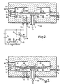
- Each ejector includes a valve device according to the invention, and Figures 2 and 3 illustrate the operation thereof.
- the essential component of the device is a valve element in the form of an actuator diaphragm 42.
- the actuator diaphragm 42 comprises a disc 44 of piezoelectric ceramic bonded to a brass disk base plate 46 with glue.
- the piezoelectric disc 44 has a metallised layer 48, and is polarised in the direction away from the base plate 46.
- the actuator diaphragm 42 is mounted within a valve housing comprising sections 49 and 50.
- the lower section 50 has an outlet port 52 forming a valve seat 55 and connection 54.
- the output 52 is mounted in the housing section 50 in a screw thread 67, and can thus be adjusted to set the position of its valve seat 55 relative to the diaphragm 42.
- the section 50 which is constructed of an insulating plastic, also contains air tight electrical connecting rods 56, 58 which allow external connection of a driving voltage to the actuator surface 48 and base plate 46, via internal wires 60, 62.
- the wires 60, 62 are of thin flexible construction to allow free movement of the actuator diaphragm 42.
- the driving voltage is derived from a high voltage direct current power source 64, which is switched under the control of a signal generator 66 with a buffer comprising transistors 68, 70, 72 and resistors 74, 76.
- the signal generator 66 is replaced by a signal source which corresponds to the presence of unwanted particles in the particle stream.
- the driving voltage is shaped by the resistor 78, and the inherent capacitance of the piezoelectric ceramic 44, into an exponential ramp waveform.
- the upper valve housing section 49 contains the inlet 51, a portion of the connection 54 and stop 53.
- the actuator diaphragm 42 is held in place by its outer edge which rests on a circular rim 80 on the lower section 50.
- the distance between the outer support rim 80 and the valve seat 55 is controlled so that when the valve is assembled and in a depressurised state, a small gap 57 is maintained between the actuator diaphragm 42 and the valve seat 55.
- valve When the valve is initially pressurized by supply air 59, it changes from the state shown in Figure 2 to that shown in Figure 3. This change is caused by a force resulting from a differential pressure acting on the valve plate 42.
- the differential pressure arises because the outlet port 52 is at a low pressure nearly equal to atmospheric, and thus much lower than the pressure in chamber 61, 63, and because of the small spacing between the diaphragm 42 and the output port 52. This spacing is normally no more than 0,13 mm (5 thousandths of an inch) and usually in the range 0,051 - 0,076 mm (2 - 3 thousandths of an inch).
- the pressure differential urges the diaphragm 42 toward the valve seat 55. Once the diaphragm 42 closes against the seat 55, the air flow through the gap 57 is reduced to an insignificant level and the valve is now closed as shown in Figure 3.
- the pressure difference between the supply pressure in chamber 61, 63 and the exhaust pressure (atmospheric) in outlet port 52 acts across the area of the actuator diaphragm 42 that is enclosed by the valve seat 55. This pressure differential acting on this area provides the force required to hold the actuator diaphragm 42 in the closed position against the elastic stresses in the diaphragm 42.
- Appropriate adjustment of the position of the output port 52 can ensure that the diaphragm is in substantial equilibrium for a given input pressure with the contact pressure between the diaphragm 42 and the valve seat 55 substantially zero.
- a typical pressure for particle sorting is in the range 2,1 to 2,75 BAR (30 to 40 psi).
- the piezoelectric force alone would be insufficient to overcome the force holding the valve closed, as described above.
- the valve construction is such that the gap 57 becomes closed as the actuator diaphragm 42 is further deformed when the air pressure is applied. This pre-loads the actuator diaphragm with a force which is in the direction that assists opening of the valve. Hence the piezoelectric force required to open the valve is reduced.
- Ejectors in particle sorting apparatus must be able to operate at great speed and frequency, sometimes well in excess of 500 cycles/sec.
- the pneumatic pulse generated in an ejector having a valve device of the type just described must start and finish abruptly, so that the ejection pulse will then have full pressure while the unwanted particle is present (to maximize ejection force).
- This is achieved by the pre-loading of the actuator diaphragm 42 which causes the valve to snap open when the piezoelectric ceramic disc 44 is energized.
- the pressure differential described above causes the valve also to snap closed when the piezoelectric ceramic disc 44 is de-energized.
- the snap action of the valve also enables the opening and closing times to be accurately predicted. This is particularly useful in a particle sorting system which requires precise timing of ejector pulses to ensure that the ejectors remove only unwanted particles from the product stream.
- the pressure profile of the ejection pulse should be flat with minimal overshoot and minimal oscillation, so that in a sorting apparatus there is a uniform force available to remove unwanted particles.
- Overshoot and oscillation of the ejector valve pneumatic output pulse is primarily due to the valve plate oscillating at its mechanical resonant frequency.
- the above construction enables the diaphragm 42 to move to a closed position with the differential air input pressure just balancing elastic forces in the diaphragm tending to hold the valve open. In this position there is little pressure exerted on the valve seat 55, and hence little wear, leading to a long operational life.
- the driving voltage is applied, the movement of the diaphragm 42 away from the seat 55 is limited by a stop of relatively large area, which may be adapted to the shape of the diaphragm to further minimise wear thereon.
- the operating temperature should be maintained substantially steady.
- the device of Figures 2 and 3 can include one or more bleed ducts 82, which may be equipped with valves 84 to provide for variable flow therethrough.
- air from the source can flow through the device, thereby controlling its temperature at a desired level.
- Some leakage may also be permitted into the output port 52, but this may be insufficient to provide temperature control.
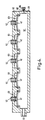
- five output ports 52 are mounted in one housing section 50. These ports are closed by respective diaphragms 42 supported around their peripheries in cylindrical mounts 86.
- the mounts 86 have openings therein to ensure that the chamber 63 behind the diaphragms 42 is maintained at the same pressure as the main chamber 61.
- a bleed duct 82 is formed in housing section 49, and coupled to control valve 84 to provide for a variable flow of air through the device for cooling.
- the outlet ports 52 are adjustably mounted in the housing section 50. This enables each to be set relative to its respective diaphragm to minimise contact pressure therebetween in the closed position. Stops (not shown) may also be included to limit the movement of the diaphragms 42 away from their respective output ports 52.
- the dual nozzle ejector unit shown in Figures 5 and 6 comprises essentially a pair of valve devices which each operate in the manner of that described above with reference to Figures 2 and 3, but disposed back to back, and sharing a common central chamber behind each actuator diaphragm.
- the ejector housing comprises a central section 102 and two side sections 104.
- the central section 102 has a cylindrical opening 106 in which a central boss 108 is supported on spokes 110.
- actuator diaphragms 112 At the ends of the cylinder 106 are located actuator diaphragms 112, each comprising a laminate of the kind illustrated in Figure 2.
- the diaphragms 112 are held in place by non-sealing locating rings 114 which are themselves held in place by being anchored to each other by bolts extending through the central section 102 as indicated.
- the side sections 104 are mounted directly on the central section 102, and have regions 116 which directly overlay the locating rings 114. Centrally located on each of regions 116 is an outlet port 118 which, in the assembled unit, is in communication with a delivery duct 120 defined between the central section 102 and each side section 104.
- the two delivery ducts 120 lead to respective ejector nozzles 122.
- each diaphragm 112 and region 116 of a side section within the clamping ring 114 constitutes a discharge chamber equivalent to the chamber 63 in the device shown in Figure 2.
- this chamber has provision for adjustment which can vary the mounting of the output port 118 relative to the central section 102, and thereby the operating characteristics of the respective valve.
- Six screws 124 disposed around the periphery of region 116 cooperate with the central section 102 and the clamping ring 104 to enable the output port to be moved toward or away from the stop 108 and thereby the diaphragm 112.
- This facility exploits the flexibility of each side section 104, and provides for the unit to be adjusted as it is assembled to provide the sealing between the diaphragm and the output port when the valve is in the closed position.
- the unit shown in Figure 5 has a single air inlet port 126 which enables fluid under pressure to be delivered to the central chamber 106 and the two discharge chambers defined within the clamping rings 114.
- a connector 128 is provided for connecting a driving circuit to the piezoelectric disc on each diaphragm 112, again substantially in the manner described above with reference to Figures 2 and 3.
- a plurality of units of the kind shown in Figure 4 can be arranged side by side.
- a small spacing should be provided between adjacent units to allow for flexure of the region 116 of the side sections 104.
- annular seals may be fitted around the peripheries of the regions 116.
Landscapes
- Engineering & Computer Science (AREA)
- General Engineering & Computer Science (AREA)
- Mechanical Engineering (AREA)
- Electrically Driven Valve-Operating Means (AREA)
- Sorting Of Articles (AREA)
- Multiple-Way Valves (AREA)
Claims (21)
- Ventilvorrichtung zum Regeln der Zufuhr von Gas von einer Druckquelle, umfassend ein Gehäuse (49, 50), das eine Druckkammer (61, 63) definiert, eine Membran (42), die in dem Gehäuse montiert ist und ein piezoelektrisches Element (44) umfaßt, einen Eingang (59) für den Anschluß an eine Druckgasquelle, wobei der Eingang mit der Kammer (61, 63) auf beiden Seiten der Membran (42) in Verbindung steht, und einen Ausgangsport (52) auf einer Seite der Membran, wobei ein Bereich der Membran (42) in Nebeneinanderlage mit dem Ausgangsport (52) angeordnet ist, und die Membran sich durch ein Gasdruckdifferential über ihren genannten Bereich elastisch verformen kann, so daß der genannte Bereich den Ausgangsport (52) schließt, wobei die Ventilvorrichtung einen Stromkreis (64) aufweist, der selektiv betätigt werden kann, um das piezoelektrische Element (44) dazu zu aktivieren, den genannten Bereich der Membran von dem Ausgangsport zurückzuziehen, um Gas aus der Druckkammer zum Ausgangsport einzulassen, dadurch gekennzeichnet, daß das genannte Druckdifferential in der geschlossenen Position durch elastische Kräfte in der Membran (42) ausgeglichen wird, so daß der Angriffsdruck zwischen der Membran (42) und dem Umfang des Ausgangsports (52) im wesentlichen Null ist.
- Ventilvorrichtung nach Anspruch 1, bei der der Ausgangsport (52) und die Membran (42) kreisförmig sind, wobei die Mitte der Membran auf der Achse des Ausgangsports liegt.
- Ventilvorrichtung nach Anspruch 1 oder Anspruch 2, bei der die Position des Ausgangsports (52) in dem Gehäuse verstellbar ist, um den Angriffsdruck zwischen der Membran (42) und dem Umfang des Ausgangsports (52) in der geschlossenen Position bei einem bestimmten Eingangsdruck im wesentlichen auf Null einzustellen.
- Ventilvorrichtung nach einem der vorherigen Ansprüche, bei der ein piezoelektrischer Abschnitt der genannten Membran (42) in Nebeneinanderlage mit dem Ausgangsport ist.
- Ventilvorrichtung nach einem der vorherigen Ansprüche, bei der das Gehäuse mit einem Anschlag (23) hinter der genannten Membran ausgebildet ist, um das Ausmaß ihres Rückzugs vom Ausgangsport in Reaktion auf die Aktivierung des piezoelektrischen Elementes zu begrenzen.
- Ventilvorrichtung nach einem der vorherigen Ansprüche, bei der die Membran die Druckkammer überquert und in die diskreten Abschnitte (61, 63) unterteilt, wobei das Gehäuse ein Mittel zum Verbinden des Eingangs mit beiden Abschnitten beinhaltet.
- Ventilvorrichtung nach Anspruch 6, bei der die Druckkammer die Form eines Zylinders hat, wobei die genannte Membran (42) dessen Achse und den Ausgangsport (52) im wesentlichen auf der genannten Achse überquert.
- Ventilvorrichtung nach einem der vorherigen Ansprüche mit einer elektronischen Dämpfungsschaltung für das piezoelektrische Element.
- Druckluftauswerfer für eine Sortiervorrichtung, bei dem zu sortierendes Material in einem Strom gerichtet wird, der einem Luftweg folgt, und zurückgewiesenes Material durch Luftimpulse von solchen Auswerfern aus dem Strom beseitigt wird, wobei der Auswerfer (12) folgendes umfaßt: ein Gehäuse (49, 50), das eine Druckkammer (61, 63) definiert; eine Membran (42), die in dem Gehäuse montiert ist und ein piezoelektrisches Element (44) umfaßt; einen Eingang (59) für den Anschluß an eine Druckgasquelle, wobei der Eingang (59) mit der Kammer auf beiden Seiten der Membran (42) in Verbindung steht; und einen Ausgangsport (52), der die Kammer auf einer Seite der Membran mit einer Zuführungsrohrleitung verbindet, die in einer Auswerferdüse (12) endet, wobei ein Bereich der Membran in Nebeneinanderlage mit dem Ausgangsport angeordnet ist und die Membran so ausgestaltet ist, daß sie sich durch Eingangsdruckdifferential über ihren genannten Bereich elastisch verformt, so daß dieser genannte Bereich den Ausgangsport (52) schließt, dadurch gekennzeichnet, daß in der geschlossenen Position das genannte Druckdifferential (42) durch elastische Kräfte in der Membran ausgeglichen wird, so daß der Angriffsdruck zwischen der Membran (42) und dem Umfang des Ausgangsports (52) im wesentlichen Null ist, wobei die Ventilvorrichtung einen Stromkreis aufweist, der selektiv betätigt werden kann, um das piezoelektrische Element (44) dazu zu aktivieren, den genannten Bereich der Membran von dem Ausgangsport (52) zurückzuziehen, um Gas von der Druckkammer in den Ausgangsport und von dort in die Auswerferdüse (12) einzulassen.
- Druckluftauswerfer nach Anspruch 9, bei dem das Gehäuse mit einer Entlüftungsrohrleitung von der Kammer ausgebildet ist, die einen ständigen Strom von Gas durch die Kammer zum Regeln von deren Temperatur zuläßt.
- Druckluftauswerfer nach Anspruch 10 mit einem Ventil in der Entlüftungsrohrleitung (82) zum Regeln des Stromes von Gas durch diese.
- Druckluftauswerfer nach einem der Ansprüche 9 bis 11, bei dem die Druckkammer die Form eines Zylinders hat, wobei die genannte Membran deren Achse und den Ausgangsport im wesentlichen auf der genannten Achse überquert und wobei der Eingang am Umfang des Zylinders angeordnet ist.
- Druckluftauswerfer nach einem der Ansprüche 9 bis 12, bei dem das Gehäuse einen Mittelabschnitt und zwei Seitenabschnitte umfaßt, wobei in jedem Seitenabschnitt ein jeweiliger Ausgangsport ausgebildet und mit einem verstellbaren Montagemechanismus am Mittelabschnitt angebracht ist, so daß der Schließdruck zwischen einem Ausgangsport (52) und einer jeweiligen Membran (42) durch Einstellen eines genannten Montagemechanismus geändert werden kann.
- Druckluftauswerfer nach einem der Ansprüche 9 bis 13, bei dem der Ausgangsport an einem elastisch flexiblen Abschnitt des Gehäuses montiert ist.
- Druckluftauswerfereinheit für eine Sortiervorrichtung, bei der zu sortierendes Material in einem Strom gerichtet wird, der einem Luftweg folgt, und zurückgewiesenes Material mit Luftimpulsen von solchen Auswerfern (12) beseitigt wird, wobei der Auswerfer (12) folgendes umfaßt: ein Gehäuse, das eine Druckkammer mit einer Mehrzahl von Ausgangsports (52) definiert, die jeweils mit einer Auswerferdüse (12) verbunden sind; eine Membran (42), die in Nebeneinanderlage mit dem Ausgangsport angeordnet ist und ein piezoelektrisches Element (44) umfaßt; und einen Eingang für den Anschluß an eine Druckgasquelle, wobei der Eingang mit der Kammer auf beiden Seiten der Membran (44) in Verbindung steht, wobei ein Bereich jeder Membran (42) in Nebeneinanderlage mit ihrem jeweiligen Ausgangsport (52) angeordnet ist und jede Membran so ausgestaltet ist, daß sie durch ein Eingangsdruckdifferential über ihren genannten Bereich elastisch verformt werden kann, so daß der genannte Bereich den jeweiligen Ausgangsport (52) schließt, dadurch gekennzeichnet, daß in der geschlossenen Position das genannte Druckdifferential durch elastische Kräfte in der Membran (42) ausgeglichen wird, so daß der Angriffsdruck zwischen der Membran und dem Umfang des Ausgangsports (52) im wesentlichen Null ist, wobei die Auswerfereinheit (12) einen Stromkreis beinhaltet, der selektiv betätigt werden kann, um die piezoelektrischen Elemente dazu zu aktivieren, die Membranen (42) von dem Ausgangsport zurückzuziehen, um Gas von der Druckkammer in die Auswerferdüsen (12) einzulassen.
- Druckluftauswerfereinheit nach Anspruch 15, bei der das Gehäuse mit einer Entlüftungsrohrleitung (82) von der Kammer ausgebildet ist, die einen ständigen Fluß von Gas durch die Kammer zum Regeln von deren Temperatur zuläßt.
- Druckluftauswerfereinheit nach Anspruch 15 oder Anspruch 16 mit zwei Ausgangsports (52) jeweils in einer diskreten Region der Druckkammer, wobei die Seiten der Membranen (42) ihren jeweiligen Ausgangsports (52) zugewandt sind und die genannten Regionen sowie die Regionen zwischen den Membranen mit dem Eingang in Verbindung stehen.
- Druckluftauswerfereinheit nach Anspruch 17, bei der die Membranen (42) eine mittlere Kammerregion mit Ausgangsportregionen auf beiden Seiten davon definieren.
- Druckluftauswerfereinheit nach Anspruch 18 mit einem Anschlag (53), der in der mittleren Region angeordnet ist, um das Ausmaß des Rückzugs jeder Membran (42) von ihrem benachbarten Ausgangsport in Reaktion auf die Aktivierung des jeweiligen piezoelektrischen Elementes zu begrenzen.
- Druckluftauswerfer nach Anspruch 19, bei dem die Druckkammer im wesentlichen zylindrisch ist, wobei die Ausgangsports (52) und der Anschlag (53) im wesentlichen auf deren Achse ausgerichtet ist.
- Mehrzahl von Auswerfern (12) nach einem der Ansprüche 9 bis 20, Seite an Seite in einer Anordnung mit Abstand dazwischen angeordnet.
Applications Claiming Priority (3)
| Application Number | Priority Date | Filing Date | Title |
|---|---|---|---|
| US08/347,957 US5628411A (en) | 1994-12-01 | 1994-12-01 | Valve devices for use in sorting apparatus ejectors |
| US347957 | 1994-12-01 | ||
| PCT/GB1995/002795 WO1996017192A1 (en) | 1994-12-01 | 1995-11-29 | Piezoelectric diaphragm valve for use in sorting apparatus ejectors |
Publications (2)
| Publication Number | Publication Date |
|---|---|
| EP0795099A1 EP0795099A1 (de) | 1997-09-17 |
| EP0795099B1 true EP0795099B1 (de) | 1999-01-13 |
Family
ID=23366029
Family Applications (1)
| Application Number | Title | Priority Date | Filing Date |
|---|---|---|---|
| EP95938506A Expired - Lifetime EP0795099B1 (de) | 1994-12-01 | 1995-11-29 | Piezoelektrisches membranventil für einen sortierungsauswerfer |
Country Status (6)
| Country | Link |
|---|---|
| US (1) | US5628411A (de) |
| EP (1) | EP0795099B1 (de) |
| JP (1) | JP3652703B2 (de) |
| AU (1) | AU3987595A (de) |
| ES (1) | ES2126949T3 (de) |
| WO (1) | WO1996017192A1 (de) |
Families Citing this family (52)
| Publication number | Priority date | Publication date | Assignee | Title |
|---|---|---|---|---|
| SE9600913L (sv) * | 1996-03-08 | 1997-02-03 | Siemens Elema Ab | Ventil |
| US5831371A (en) * | 1996-11-22 | 1998-11-03 | Face International Corp. | Snap-action ferroelectric transducer |
| US6086041A (en) * | 1997-04-07 | 2000-07-11 | Mccord Winn Textron Inc. | Multi-valve module having a ceramic piezoelectric actuator |
| WO1999031420A1 (fr) * | 1997-12-12 | 1999-06-24 | Smc Kabushiki Kaisha | Soupape piezo-electrique |
| US6019346A (en) * | 1998-03-06 | 2000-02-01 | Miller; Kenneth L. | Piezo-actuated high response valve |
| US5984258A (en) * | 1998-09-28 | 1999-11-16 | General Motors Corporation | Method and apparatus for control of a shape memory alloy actuator for a fuel injector |
| DE19931990C1 (de) * | 1999-07-09 | 2001-01-11 | Festo Ag & Co | Elektroventil |
| US7410063B1 (en) * | 1999-08-09 | 2008-08-12 | The United States Of America As Represented By The Secretary Of The Army | Method and system for sorting particles sampled from air |
| EP1106882A3 (de) * | 1999-12-09 | 2002-11-13 | Drei-S-Werk Präzisionswerkzeuge GmbH & Co. Fertigungs-KG | Piezoelektrisch betätigbares Ventil |
| US6589229B1 (en) | 2000-07-31 | 2003-07-08 | Becton, Dickinson And Company | Wearable, self-contained drug infusion device |
| US6685164B1 (en) * | 2000-09-11 | 2004-02-03 | Hamai Industries Limited | Control valve and diaphragm for use in the control valve |
| EP1229278B1 (de) * | 2001-01-31 | 2005-10-12 | Caterpillar Inc. | Piezoelektrischer Aktor |
| US7061161B2 (en) | 2002-02-15 | 2006-06-13 | Siemens Technology-To-Business Center Llc | Small piezoelectric air pumps with unobstructed airflow |
| US7016518B2 (en) * | 2002-03-15 | 2006-03-21 | Extreme Cctv Inc. | Vehicle license plate imaging and reading system for day and night |
| EP1357321A1 (de) * | 2002-04-26 | 2003-10-29 | Siemens Aktiengesellschaft | Piezoelektrisch betätigbares Ventil |
| ATE271670T1 (de) * | 2002-05-31 | 2004-08-15 | Festo Ag & Co | Piezoventil |
| US20030226987A1 (en) * | 2002-06-06 | 2003-12-11 | Gallmeyer Christopher F. | Method and apparatus for seat detection and soft seating in a piezoelectric device actuated valve system |
| US7624964B2 (en) * | 2002-10-04 | 2009-12-01 | Pbt (Ip) Limited | Gas valve with proportional output |
| US20040144696A1 (en) | 2003-01-29 | 2004-07-29 | Stewart Mills | Valve device for use in sorting apparatus ejectors |
| JP4344164B2 (ja) * | 2003-04-18 | 2009-10-14 | 株式会社サタケ | 圧電式エアバルブおよび複合圧電式エアバルブ |
| FR2864197B1 (fr) * | 2003-12-18 | 2006-04-28 | Eaton Sa Monaco | Vanne hydraulique a rondelle piezoelectrique |
| DE102004002111B4 (de) * | 2004-01-14 | 2007-04-12 | Dbt Gmbh | Piezoelektrische Aktoreinheit für den Bergbau |
| GB2416533B (en) * | 2004-07-27 | 2008-06-18 | Sortex Ltd | Chutes for sorting and inspection apparatus |
| WO2006083635A2 (en) * | 2005-01-28 | 2006-08-10 | Satake Usa, Inc. | Multiport ejector for use with sorter |
| US7321185B2 (en) * | 2005-03-04 | 2008-01-22 | United States Of America As Represented By The Administrator Of The National Aeronautics And Space Administration | Active multistable twisting device |
| US20080085293A1 (en) * | 2006-08-22 | 2008-04-10 | Jenchen Yang | Drug eluting stent and therapeutic methods using c-Jun N-terminal kinase inhibitor |
| DE112007003042B4 (de) * | 2006-12-27 | 2011-11-03 | Murata Manufacturing Co., Ltd. | Piezoelektrisches Ventil |
| US7849870B2 (en) * | 2007-11-01 | 2010-12-14 | Honeywell International Inc. | Piezoelectric pressure control valve |
| US7841579B2 (en) * | 2007-11-01 | 2010-11-30 | Honeywell International Inc. | Piezoelectric actuator with a gimballed valve |
| WO2009157474A1 (ja) | 2008-06-27 | 2009-12-30 | 株式会社村田製作所 | マイクロバルブ及びバルブシート部材 |
| US8247724B2 (en) * | 2008-10-20 | 2012-08-21 | Buhler Sortex Ltd. | Chutes for sorting and inspection apparatus |
| GB0822163D0 (en) * | 2008-12-05 | 2009-01-14 | Rolls Royce Plc | A valve |
| CN102449363B (zh) * | 2009-05-25 | 2015-02-04 | 株式会社村田制作所 | 阀、流体装置及流体供给装置 |
| DE102009039211A1 (de) | 2009-08-28 | 2011-03-03 | Festo Ag & Co. Kg | Sortierverfahren und zugehörige Sortiervorrichtung |
| CN101915230B (zh) * | 2010-08-03 | 2013-01-30 | 清华大学 | 一种真空排水系统集水界面单元的气动执行设备 |
| JP5764049B2 (ja) * | 2011-12-13 | 2015-08-12 | 株式会社サタケ | 圧電式バルブ及び該圧電式バルブを利用した噴風手段を備える光学式粒状物選別機 |
| WO2013157548A1 (ja) * | 2012-04-20 | 2013-10-24 | 株式会社サタケ | 圧電式バルブ、及び該圧電式バルブを利用した噴風手段を備える光学式粒状物選別機 |
| JP5795292B2 (ja) * | 2012-09-06 | 2015-10-14 | 富士ゼロックス株式会社 | 液滴吐出装置 |
| EP2722568A1 (de) * | 2012-10-17 | 2014-04-23 | RECO Gesellschaft für Industriefilterregelung mbH | Membranventil mit mindestens zwei Funktionsflächen |
| GB201219184D0 (en) * | 2012-10-25 | 2012-12-12 | Buhler Sortex Ltd | Adaptive ejector valve array |
| FR3006207A1 (fr) * | 2013-05-30 | 2014-12-05 | Commissariat Energie Atomique | Carte fluidique comportant un canal fluidique pourvu d'une ouverture refermable par un film souple |
| JP1525031S (de) * | 2014-08-07 | 2015-06-01 | ||
| DE102016217435B4 (de) * | 2016-09-13 | 2018-08-02 | Albert-Ludwigs-Universität Freiburg | Fluidpumpe und Verfahren zum Betreiben einer Fluidpumpe |
| DE102016219658C5 (de) * | 2016-10-11 | 2020-07-23 | Conti Temic Microelectronic Gmbh | Ventilvorrichtung für ein Fahrzeug, sowie Sitzanlage für ein Fahrzeug |
| JP7344012B2 (ja) * | 2019-06-07 | 2023-09-13 | 株式会社堀場エステック | 流体制御バルブ、流量制御装置、及び、駆動回路 |
| CN112160391B (zh) * | 2020-09-09 | 2021-08-31 | 汉宇集团股份有限公司 | 一种喷头、应用该喷头的冲洗装置及电坐便器便座 |
| KR102245750B1 (ko) * | 2020-11-25 | 2021-04-28 | 주식회사 에이.엠.씨 | 자력을 이용한 비접촉 연속 압전 발전기 |
| CN114688296B (zh) * | 2020-12-29 | 2023-05-16 | 上海微电子装备(集团)股份有限公司 | 气动控制装置及系统、光刻设备 |
| DE102021121334A1 (de) * | 2021-04-27 | 2022-10-27 | Dürr Systems Ag | Piezo-Aktorvorrichtung |
| CN216407869U (zh) * | 2021-06-22 | 2022-04-29 | 科际精密股份有限公司 | 气压调节装置 |
| SE547330C2 (en) * | 2022-06-09 | 2025-07-01 | Staccato Tech Ab | An electromechanical valve |
| US20240360915A1 (en) * | 2023-04-28 | 2024-10-31 | Humphrey Products Company | Peizoelectric valve assembly |
Family Cites Families (26)
| Publication number | Priority date | Publication date | Assignee | Title |
|---|---|---|---|---|
| BE426805A (de) * | 1937-03-16 | |||
| US2928409A (en) * | 1955-01-31 | 1960-03-15 | Textron Inc | Non-magnetic electro hydraulic transfer valve |
| US3229956A (en) * | 1962-03-02 | 1966-01-18 | Stevens Mfg Co Inc | Diaphragm fluid valve |
| US3275285A (en) * | 1963-09-23 | 1966-09-27 | Therm O Disc Inc | Thermoelectric valve |
| US3465732A (en) * | 1967-10-19 | 1969-09-09 | Physics Int Co | Piezoelectric control valve |
| US3683212A (en) * | 1970-09-09 | 1972-08-08 | Clevite Corp | Pulsed droplet ejecting system |
| US3669142A (en) * | 1970-10-16 | 1972-06-13 | Grove Valve & Regulator Co | Expansible tube valve with low pressure bleed |
| US4053136A (en) * | 1975-06-05 | 1977-10-11 | The Tappan Company | Control circuit and adjustable valve for a gas appliance |
| US4093883A (en) * | 1975-06-23 | 1978-06-06 | Yujiro Yamamoto | Piezoelectric multimorph switches |
| IL52446A (en) * | 1977-07-04 | 1981-10-30 | Barmad Kibbutz Evron | Diaphragm valves |
| GB2025038B (en) * | 1978-06-28 | 1982-11-24 | Gunsons Sortex Ltd | Method and apparatus for sorting agricultural products |
| US4340083A (en) * | 1978-11-30 | 1982-07-20 | Carleton Controls Corporation | Deflectable beam valve |
| JPS608384B2 (ja) * | 1980-07-26 | 1985-03-02 | ダイキン工業株式会社 | バイモルフ圧電素子を用いた弁 |
| DE3174515D1 (en) * | 1981-01-19 | 1986-06-05 | Gunsons Sortex Ltd | Sorting machine |
| US4545561A (en) * | 1982-07-30 | 1985-10-08 | Mcdonnell Douglas Corporation | Piezoelectric valve operator |
| GB2151018B (en) * | 1983-12-06 | 1987-07-22 | Gunsons Sortex Ltd | Sorting machine and method |
| US4903732A (en) * | 1989-01-19 | 1990-02-27 | A. K. Allen Company | Piezoelectric valve |
| DE3935474A1 (de) * | 1989-06-22 | 1991-01-03 | Hoechst Ceram Tec Ag | Piezoelektrischer biegewandler und seine verwendung |
| US5238223A (en) * | 1989-08-11 | 1993-08-24 | Robert Bosch Gmbh | Method of making a microvalve |
| JPH03186674A (ja) * | 1989-12-13 | 1991-08-14 | Nissan Motor Co Ltd | 圧電弁装置 |
| FR2664671B1 (fr) * | 1990-07-12 | 1992-10-09 | Centre Nat Rech Scient | Vanne et dispositif de distribution multivoies, notamment pour fluides corrosifs. |
| AT396392B (de) * | 1991-09-30 | 1993-08-25 | Hoerbiger Fluidtechnik Gmbh | Piezo-ventil |
| GB9122739D0 (en) * | 1991-10-25 | 1991-12-11 | The Technology Partnership Ltd | System for controlling fluid flow |
| US5203537A (en) * | 1992-03-09 | 1993-04-20 | Teledyne Industries, Inc. | Piezoceramic valve actuator sandwich assembly and valve incorporating such an assembly |
| AT398331B (de) * | 1992-04-03 | 1994-11-25 | Hoerbiger Fluidtechnik Gmbh | Elektro-pneumatischer signalwandler |
| US5340081A (en) * | 1993-06-07 | 1994-08-23 | The United States Of America As Represented By The United States Department Of Energy | Means for positively seating a piezoceramic element in a piezoelectric valve during inlet gas injection |
-
1994
- 1994-12-01 US US08/347,957 patent/US5628411A/en not_active Expired - Lifetime
-
1995
- 1995-11-29 EP EP95938506A patent/EP0795099B1/de not_active Expired - Lifetime
- 1995-11-29 WO PCT/GB1995/002795 patent/WO1996017192A1/en not_active Ceased
- 1995-11-29 JP JP51843696A patent/JP3652703B2/ja not_active Expired - Fee Related
- 1995-11-29 AU AU39875/95A patent/AU3987595A/en not_active Abandoned
- 1995-11-29 ES ES95938506T patent/ES2126949T3/es not_active Expired - Lifetime
Also Published As
| Publication number | Publication date |
|---|---|
| WO1996017192A1 (en) | 1996-06-06 |
| US5628411A (en) | 1997-05-13 |
| JPH10510040A (ja) | 1998-09-29 |
| AU3987595A (en) | 1996-06-19 |
| ES2126949T3 (es) | 1999-04-01 |
| EP0795099A1 (de) | 1997-09-17 |
| JP3652703B2 (ja) | 2005-05-25 |
Similar Documents
| Publication | Publication Date | Title |
|---|---|---|
| US5628411A (en) | Valve devices for use in sorting apparatus ejectors | |
| US6062256A (en) | Micro mass flow control apparatus and method | |
| US6722581B2 (en) | Synthetic jet actuators | |
| US4695034A (en) | Fluid control device | |
| US6827559B2 (en) | Piezoelectric micropump with diaphragm and valves | |
| US5593134A (en) | Magnetically assisted piezo-electric valve actuator | |
| US4364059A (en) | Ink jet printing apparatus | |
| EP0071905B1 (de) | Regulierbarer Reflektor mit nicht perforierter reflektierender Membrane | |
| JPH10169827A (ja) | 流体コンジットシステム及びバルブアレイ | |
| KR970001772B1 (ko) | 미사일 제어 핀 작동기 시스템 | |
| US6086041A (en) | Multi-valve module having a ceramic piezoelectric actuator | |
| WO1998037343A9 (en) | Micro mass flow control apparatus and method | |
| JPH11246072A (ja) | 高速可変流量バルブ | |
| GB2239553B (en) | Flow rate control valve | |
| GB2131130A (en) | Piezoelectric fluid control device | |
| US20160016200A1 (en) | Pneumatic product sorting apparatus | |
| Biegelsen et al. | AirJet paper mover: An example of mesoscale MEMS | |
| TWI881167B (zh) | 壓電式閥 | |
| TWI721241B (zh) | 流體系統 | |
| US20190101111A1 (en) | Fluid system | |
| KR920008782B1 (ko) | 전기 신호-압력 신호 변환기 | |
| JP4555383B1 (ja) | 搬送部品の空圧作用システム及び部品搬送装置 | |
| TWI696818B (zh) | 微粒監測模組 | |
| US5526695A (en) | Pulsed flow meter | |
| US3621864A (en) | Electricity-fluid pressure converter |
Legal Events
| Date | Code | Title | Description |
|---|---|---|---|
| PUAI | Public reference made under article 153(3) epc to a published international application that has entered the european phase |
Free format text: ORIGINAL CODE: 0009012 |
|
| 17P | Request for examination filed |
Effective date: 19970521 |
|
| AK | Designated contracting states |
Kind code of ref document: A1 Designated state(s): ES GB IT |
|
| GRAG | Despatch of communication of intention to grant |
Free format text: ORIGINAL CODE: EPIDOS AGRA |
|
| 17Q | First examination report despatched |
Effective date: 19971002 |
|
| GRAG | Despatch of communication of intention to grant |
Free format text: ORIGINAL CODE: EPIDOS AGRA |
|
| GRAG | Despatch of communication of intention to grant |
Free format text: ORIGINAL CODE: EPIDOS AGRA |
|
| GRAH | Despatch of communication of intention to grant a patent |
Free format text: ORIGINAL CODE: EPIDOS IGRA |
|
| GRAH | Despatch of communication of intention to grant a patent |
Free format text: ORIGINAL CODE: EPIDOS IGRA |
|
| GRAA | (expected) grant |
Free format text: ORIGINAL CODE: 0009210 |
|
| AK | Designated contracting states |
Kind code of ref document: B1 Designated state(s): ES GB IT |
|
| REG | Reference to a national code |
Ref country code: ES Ref legal event code: FG2A Ref document number: 2126949 Country of ref document: ES Kind code of ref document: T3 |
|
| ITF | It: translation for a ep patent filed | ||
| PLBE | No opposition filed within time limit |
Free format text: ORIGINAL CODE: 0009261 |
|
| STAA | Information on the status of an ep patent application or granted ep patent |
Free format text: STATUS: NO OPPOSITION FILED WITHIN TIME LIMIT |
|
| 26N | No opposition filed | ||
| REG | Reference to a national code |
Ref country code: GB Ref legal event code: IF02 |
|
| PGFP | Annual fee paid to national office [announced via postgrant information from national office to epo] |
Ref country code: GB Payment date: 20131122 Year of fee payment: 19 |
|
| PGFP | Annual fee paid to national office [announced via postgrant information from national office to epo] |
Ref country code: ES Payment date: 20131120 Year of fee payment: 19 Ref country code: IT Payment date: 20131126 Year of fee payment: 19 |
|
| GBPC | Gb: european patent ceased through non-payment of renewal fee |
Effective date: 20141129 |
|
| PG25 | Lapsed in a contracting state [announced via postgrant information from national office to epo] |
Ref country code: GB Free format text: LAPSE BECAUSE OF NON-PAYMENT OF DUE FEES Effective date: 20141129 |
|
| REG | Reference to a national code |
Ref country code: ES Ref legal event code: FD2A Effective date: 20151229 |
|
| PG25 | Lapsed in a contracting state [announced via postgrant information from national office to epo] |
Ref country code: IT Free format text: LAPSE BECAUSE OF NON-PAYMENT OF DUE FEES Effective date: 20141129 |
|
| PG25 | Lapsed in a contracting state [announced via postgrant information from national office to epo] |
Ref country code: ES Free format text: LAPSE BECAUSE OF NON-PAYMENT OF DUE FEES Effective date: 20141130 |