EP0794384A2 - Small combustion device for domestic use - Google Patents
Small combustion device for domestic use Download PDFInfo
- Publication number
- EP0794384A2 EP0794384A2 EP97100752A EP97100752A EP0794384A2 EP 0794384 A2 EP0794384 A2 EP 0794384A2 EP 97100752 A EP97100752 A EP 97100752A EP 97100752 A EP97100752 A EP 97100752A EP 0794384 A2 EP0794384 A2 EP 0794384A2
- Authority
- EP
- European Patent Office
- Prior art keywords
- burner
- furnace according
- radiation shield
- plate
- heated
- Prior art date
- Legal status (The legal status is an assumption and is not a legal conclusion. Google has not performed a legal analysis and makes no representation as to the accuracy of the status listed.)
- Granted
Links
Images

Classifications
-
- F—MECHANICAL ENGINEERING; LIGHTING; HEATING; WEAPONS; BLASTING
- F23—COMBUSTION APPARATUS; COMBUSTION PROCESSES
- F23D—BURNERS
- F23D14/00—Burners for combustion of a gas, e.g. of a gas stored under pressure as a liquid
- F23D14/02—Premix gas burners, i.e. in which gaseous fuel is mixed with combustion air upstream of the combustion zone
-
- F—MECHANICAL ENGINEERING; LIGHTING; HEATING; WEAPONS; BLASTING
- F23—COMBUSTION APPARATUS; COMBUSTION PROCESSES
- F23D—BURNERS
- F23D14/00—Burners for combustion of a gas, e.g. of a gas stored under pressure as a liquid
- F23D14/46—Details, e.g. noise reduction means
-
- F—MECHANICAL ENGINEERING; LIGHTING; HEATING; WEAPONS; BLASTING
- F23—COMBUSTION APPARATUS; COMBUSTION PROCESSES
- F23D—BURNERS
- F23D2209/00—Safety arrangements
- F23D2209/20—Flame lift-off / stability
-
- F—MECHANICAL ENGINEERING; LIGHTING; HEATING; WEAPONS; BLASTING
- F23—COMBUSTION APPARATUS; COMBUSTION PROCESSES
- F23D—BURNERS
- F23D2210/00—Noise abatement
Abstract
Description
Die Erfindung betrifft eine Feuerung, insbesondere eine Kleinfeuerung für den häuslichen Nutzungsbereich, mit einem Brenner, der eine Vielzahl von zueinander eng benachbarten Brenneraustrittsöffnungen aufweist, durch die ein Brennstoff-/Luftgemisch strömt, das stromabwärts des Brenners verbrannt wird.The invention relates to a burner, in particular a small burner for domestic use, with a burner which has a plurality of burner outlet openings which are closely adjacent to one another and through which a fuel / air mixture flows which is burned downstream of the burner.
Feuerungen dieser Art finden sich in Gasboilern oder Gasheizthermen oder -heizkessel, wobei der Brenner üblicherweise aus einem metallischen oder keramischen Werkstoff gefertigt ist. Aufgrund der vielen Austrittsöffnungen spricht man auch von einem "multiple-port" oder einem "Teppichbrenner". Diesen Brennern wird üblicherweise vorgemischtes Brennstoff-/Luftgemisch zugeführt. Der Brenner ist zumindest abschnittsweise siebartig ausgeführt und das Brennstoff-/Luftgemisch tritt durch die derart gebildeten eng benachbarten Brenneraustrittsöffnungen laminar hindurch und wird stromabwärts in einer Vielzahl von Einzelflammen verbrannt, die jeweils einzelnen Brenneraustrittsöffnungen zuzuordnen sind.Furnaces of this type can be found in gas boilers or gas heating boilers or boilers, the burner usually being made from a metallic or ceramic material. Because of the many outlet openings one speaks of a "multiple port" or a "carpet burner". Premixed fuel / air mixture is usually supplied to these burners. The burner is of sieve-like design at least in sections and the fuel / air mixture passes through the closely adjacent burner outlet openings formed in this way in laminar form and is burned downstream in a multiplicity of individual flames, which are each to be assigned to individual burner outlet openings.
An derartigen Feuerungen können Flammen-/Druckschwingungen auftreten, wie sie auch bei industriellen Verbrennungsanlagen, wie zum Beispiel Gasturbinenbrennkammern, Industrieöfen etc. bekannt sind. Während die bei den industriellen Verbrennungsanlagen auftretenden Druckschwingungen aber in der Regel vergleichsweise niedrige Frequenzen und hohe Amplituden aufweisen, sind die bei den hier beschriebenen Kleinfeuerungen auftretenden Druckschwingungen häufig durch hohe Frequenz aber niedrige Amplituden gekennzeichnet. Damit tritt an diesen Anlagen eine nicht tolerierbare akustische Belastung auf in Form eines Pfeifens. Um dieses Pfeifen beseitigen zu können, werden von den Brenner- bzw. Geräteherstellern unter hohem finanziellen Aufwand Möglichkeiten gesucht, das Auftreten dieser Verbrennungsinstabilitäten durch Änderungen am Brenner oder an der Brennkammergeometrie zu verhindern.Flame / pressure vibrations can occur on such furnaces, as are also known in industrial combustion systems, such as gas turbine combustion chambers, industrial furnaces, etc. While the pressure vibrations that occur in industrial combustion systems generally have comparatively low frequencies and high amplitudes, the pressure vibrations that occur in the small furnaces described here are often high Frequency but marked low amplitudes. This means that there is an intolerable acoustic load on these systems in the form of a whistle. In order to be able to eliminate this whistle, the burner or appliance manufacturers are looking for ways to prevent the occurrence of these combustion instabilities by changing the burner or the geometry of the combustion chamber at great expense.
Dabei weiß man zwar, daß das Auftreten dieser Schwingungen an eine diskrete Kombination der feuerungstechnischen Betriebsparameter wie thermische Leistung, Luftzahl und Brennstoffart gebunden ist, letztlich ist man aber auf empirisch erhaltene Maßnahmen angewiesen.Although it is known that the occurrence of these vibrations is linked to a discrete combination of the firing operating parameters such as thermal output, air ratio and type of fuel, ultimately one has to rely on empirically obtained measures.
Aufgabe der vorliegenden Erfindung ist es daher, eine oben beschriebene Feuerung derart weiterzubilden, daß die Schwingungen, das heißt also das Pfeifen, unter den üblichen Betriebsbedingungen im gewünschten Regelbereich der Feuerung nicht mehr auftreten.The object of the present invention is therefore to develop a furnace as described above in such a way that the vibrations, that is to say the whistling, no longer occur under the usual operating conditions in the desired control range of the furnace.
Diese Aufgabe wird erfindungsgemäß dadurch gelöst, daß die Brenneroberfläche im Bereich der Brenneraustrittsöffnungen beheizbar ist.This object is achieved in that the burner surface can be heated in the area of the burner outlet openings.
Der Erfindung liegt dabei die Erkenntnis zugrunde, daß die den Flammenteppich bildenden Einzeiflammen nicht ausreichend zündstabilisiert sind. Bei den oben angesprochenen industriellen Verbrennungsanlagen werden hierzu konstruktive Maßnahmen ergriffen. Dies ist aber bei den hier interessierenden Brennern aufgrund der Vielzahl der Austrittsöffnungen, aus denen das Brenngas-/Luftgemisch in vielen Einzelstrahlen austritt, aus wirtschaftlichen Gründen nicht vertretbar.The invention is based on the finding that the individual flames forming the carpet of flames are not sufficiently ignition-stabilized. In the industrial incineration plants mentioned above, constructive measures are taken for this. However, due to the large number of outlet openings from which the fuel gas / air mixture emerges in many individual jets, this is not acceptable for the burners of interest here for economic reasons.
Deswegen treten insbesondere bei Mager-Vormischverbrennungen von gas- oder dampfförmigen Brennstoffen Verbrennungsinstabilitäten auf. Für diese gibt es mehrere sich teilweise auch gegenseitig beeinflussende Ursachen. Zum einen ändern sich die Wärmefreisetzungsraten der Flammen periodisch, zum anderen ändert sich die axiale Position, an dem das aus der Brenneraustrittsöffnung ausströmende Gas entzündet wird, wobei diese als "Zündschwingung" bezeichnete Fluktuation der Zündzonen relativ zur Brenneroberfläche als wesentliche Ursache des Pfeifens angesehen wird.This is why combustion instabilities occur particularly in lean premix burns of gaseous or vaporous fuels. There are several mutually influencing causes for these. On the one hand the heat release rates of the flames change periodically, on the other hand the axial position changes to which the gas flowing out of the burner outlet opening is ignited, this fluctuation of the ignition zones, referred to as "ignition oscillation", relative to the burner surface being regarded as the main cause of the whistling.
Durch die erfindungsgemäße Beheizung wird jetzt eine deutlich erhöhte Brenneroberflächentemperatur erreicht, was als Folge eine erhebliche Verbesserung der Zündstabilität der Flamme hat und so die Zündschwingungen unterdrückt.The heating according to the invention now achieves a significantly increased burner surface temperature, which as a result has a considerable improvement in the ignition stability of the flame and thus suppresses the ignition oscillations.
Soweit hier von der Beheizung der Brenneroberfläche gesprochen wird, wird darunter auch verstanden, lediglich Bereiche der Brenneroberfläche entsprechend zu beheizen, in denen aufgrund der spezifischen lokalen Randbedingungen normalerweise erste Instabilitäten auftreten können, die dann entsprechende Schwingungen im gesamten Flammenteppich initiieren können.Insofar as this is referred to as heating the burner surface, it is also understood to mean that only areas of the burner surface are to be appropriately heated in which, due to the specific local boundary conditions, initial instabilities can normally occur, which can then initiate corresponding vibrations in the entire flame carpet.
Eine Möglichkeit, die Brenneroberfläche, aus der das Brennstoff-/Luftgemisch austritt, zu beheizen, ist sie mit einer Zuführvorrichtung für heiße Rauchgase zu verbinden. In diesem Fall würde die Brenneroberfläche durch Wärmetausch mit heißen, ausgebrannten Rauchgasen beheizt. Hierzu kann das Rauchgas in einer doppelwandigen Brennerplatte geführt werden, in die die Brenneraustrittsöffnungen als Durchtrittskanäle eingearbeitet sind, so daß sich die Rauchgase nicht mit dem Frischgasgemisch vermischen können.One way of heating the burner surface from which the fuel / air mixture emerges is to connect it to a supply device for hot flue gases. In this case, the burner surface would be heated by heat exchange with hot, burned-out flue gases. For this purpose, the flue gas can be guided in a double-walled burner plate, into which the burner outlet openings are incorporated as through channels, so that the flue gases cannot mix with the fresh gas mixture.
Alternativ wird vorgeschlagen, den Brenner elektrisch zu beheizen. Vorzugsweise wird der Brenner hierzu aus einem Material gefertigt, das sich bei Durchleitung eines elektrischen Stromes in ausreichendem Maße erhitzt.Alternatively, it is proposed to heat the burner electrically. For this purpose, the burner is preferably made of a material which heats up sufficiently when an electric current is passed through.
Bei einer bevorzugten Ausführungsform wird die Brenneroberfläche aber durch eine Wärmebestrahlung erwärmt, wozu ihr gegenüber ein Strahlungsschild in der Feuerung angeordnet wird. Dieses Strahlungsschild, ist ein sowohl im Verhältnis zur Brenneroberfläche als auch im Verhältnis zu der in der Regel wassergekühlten Brennkammerwand heißer Festkörper. Die von diesem ausgehende Wärmestrahlung erhöht die Temperatur der Brenneroberfläche, so daß sich bei dieser eine einheitliche, deutlich erhöhte Oberflächentemperatur einstellt, was eine Verbesserung der Zündstabilität der Flamme zur Folge hat und die Zündschwingungen unterdrückt. Es bietet sich an, das Strahlungsschild durch die Flammen oder die Rauchgase zu beheizen, die am Strahlungsschild vorbeistreifen. Diese haben eine Temperatur von ca. 1.200 - 1.400 °C, so daß das Strahlungsschild auf eine Temperatur von ca. 800 - 1.000 °C oder darüber erhitzt wird.In a preferred embodiment, however, the burner surface is heated by thermal radiation, for which purpose a radiation shield is arranged in the furnace. This radiation shield, is a solid that is hot both in relation to the burner surface and in relation to the usually water-cooled combustion chamber wall. The heat radiation emanating from this increases the temperature of the burner surface, so that a uniform, significantly increased surface temperature is set, which improves the ignition stability of the flame and suppresses the ignition oscillations. It is advisable to heat the radiation shield by the flames or the flue gases that pass the radiation shield. These have a temperature of approximately 1,200-1,400 ° C, so that the radiation shield is heated to a temperature of approximately 800-1,000 ° C or above.
Das Strahlungsschild kann dabei sowohl aus metallischem Material sein, zum Beispiel Edelstahl, oder aber auch aus keramischem Material. Wesentlich ist, daß das Material bei der hohen Temperatur widerstandsfähig gegen Oxidation etc. bleibt und die entsprechenden Strahlungseigenschaften eines Festkörperstrahlers bei einer ausreichenden Strahlungsemissivität entwickelt.The radiation shield can be made of metallic material, for example stainless steel, or it can be made of ceramic material. It is essential that the material remains resistant to oxidation etc. at the high temperature and develops the corresponding radiation properties of a solid-state radiator with sufficient radiation emissivity.
Der Abzug der Rauchgase wird unter Strömungsgesichtspunkten nicht behindert, wenn das Strahlungsschild insbesondere gitterförmig ausgebildet ist.From the point of view of flow, the extraction of the flue gases is not hindered if the radiation shield is in particular grid-shaped.
Um eine gleichmäßige Beheizung der Brenneroberfläche sicherzustellen, ist das Strahlungsschild vorzugsweise parallel zur Brenneroberfläche angeordnet, bei Ausführungsformen, bei denen eine spezielle Strahlungscharakteristik notwendig ist, ist aber auch eine geneigte Stellung des Strahlungsschildes gegenüber der Brenneroberfläche denkbar.In order to ensure uniform heating of the burner surface, the radiation shield is preferably arranged parallel to the burner surface, but in embodiments in which a special radiation characteristic is required, an inclined position of the radiation shield with respect to the burner surface is also conceivable.
Bei einem im wesentlichen rohrförmigen Brenner mit senkrechter Achse, der an seiner Mantelfläche die Brenneraustrittsöffnungen aufweist, ist eine Beheizung der Brenneroberfläche insbesondere an dem unteren Bereich notwendig an dem sie nicht durch an ihr hochstreichende Rauchgase erhitzt wird. Dies wird vorteilhafterweise durch ein konzentrisch um den Brenner herum angeordnetes Strahlungsschild erreicht, das die Form eines zylindrischen Rohres oder eines Kegelstumpfes aufweist.In the case of an essentially tubular burner with a vertical axis, which has the burner outlet openings on its outer surface, heating of the burner surface is necessary, in particular at the lower region, at which it is not heated by smoke gases which brush against it. This is advantageously done by a concentric achieved around the burner arranged radiation shield, which has the shape of a cylindrical tube or a truncated cone.
Weitere Vorteile und Merkmale der Erfindung ergeben sich aus der nachfolgenden Beschreibung von Ausführungsbeispielen. Dabei zeigt
- Figur 1
- einen durch Rauchgase beheizten Brenner;
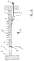
Figur 2- einen elektrisch beheizten Brenner;
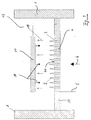
Figur 3- einen durch ein Strahlungsschild beheizten Brenner.
- Figure 1
- a burner heated by flue gases;
- Figure 2
- an electrically heated burner;
- Figure 3
- a burner heated by a radiation shield.
In Figur 1 ist eine Feuerung im Schnitt dargestellt. Diese Feuerung weist eine wassergekühlte Brennkammerwand 1 auf, wobei das an dieser Brennkammerwand anfallende Kühlwasser die Nutzwärme der Feuerung trägt. Die Temperatur der Brennkammerwand liegt dabei in einem Bereich in der Größenordnung von 100 °C. Die Brennkammerwand wird beheizt durch heiße Rauchgase mit einer Temperatur von etwa 1.200 bis 1.400 °C, die von einem Flammenteppich erzeugt werden, der sich aus einer Vielzahl von Einzeiflammen 2 zusammensetzt. Diese Einzelflammen 2 entstehen an einer Vielzahl von Brenneraustrittsöffnungen 3, die in einer Brennerplatte 4 ausgebildet sind. Dieser Brennerplatte wird über ein Zuführrohr 5 ein vorgemischtes Brenngas-/Luftgemisch 6 zugeführt, das durch die Brenneraustrittsöffnungen 3 der Brennerplatte 4 hindurchtritt und dann entsprechend verbrannt wird. Da das Brenngas-/Luftgemisch (Frischgasgemisch) selbst relativ kühl ist, insbesondere etwa Umgebungstemperatur hat, wird auch die Brennerplatte, durch die es strömt, etwa auf dieser Temperatur gehalten.In Figure 1, a furnace is shown in section. This furnace has a water-cooled combustion chamber wall 1, the cooling water accumulating on this combustion chamber wall carrying the useful heat of the furnace. The temperature of the combustion chamber wall is in the order of 100 ° C. The combustion chamber wall is heated by hot flue gases with a temperature of approximately 1,200 to 1,400 ° C., which are generated by a flame carpet which is composed of a large number of
Um die Einzelflammen 2 an der Oberfläche 4a der Brennerplatte 4 entsprechend zu stabilisieren, wird die Brennerplatte 4 beheizt. Im hier dargestellten Beispiel ist die Brennerplatte 4 hierfür zweischalig ausgebildet, indem eine Unterschale 7 mit Abstand zur Brennerplatte 4 vorgesehen ist und das Zuführrohr 5 für das Brenngas-/Luftgemisch 6 abschließt. Die Unterschale 7 ist mit Durchtrittsöffnungen 8 versehen, die über einen Zwischenraum 9 hinweg mittels Röhrchen 10 an die Brenneraustrittsöffnungen 3 angeschlossen sind. Durch den Zwischenraum 9 werden heiße Brenngase 11 hindurchgeführt, die die Brennplatte 4 entsprechend erhitzen, was an dieser über Wärmeleitung zu einer Erhöhung der Temperatur der Brenneroberfläche 4a und damit zur Stabilisierung der Einzeiflammen 2 bzw. des Flammenteppichs führt. Damit treten hier keine Flammenschwingungen mehr auf und ein bei bisherigen Brennern häufig beobachtetes Pfeifen wird so vermieden.In order to stabilize the
Die heißen Rauchgase 11 werden über eine nicht dargestellte Leitung der durch die Brennkammerwand 1 begrenzten Brennkammer 12 entnommen, an deren Boden 13 der Brenner angeordnet ist.The
In der Figur 2 ist eine alternative Beheizung für eine Brennerpiatte 4 bzw. der Brenneroberfläche 4a dargestellt. Hier wird die Beheizung mittels einer elektrischen Stromquelle 14 vorgenommen, an die die Brennerplatte 4 über ein entsprechendes Verbindungskabel 15 angeschlossen ist und aus der sie mit elektrischem Strom versorgt wird. Dieser elektrische Strom bewirkt an der Brennerplatte 4 eine Erwärmung, da deren Material dem Strom einen gewissen Widerstand entgegenstellt. Auch die hierdurch bewirkte Erwärmung der Brenneroberfläche 4a führt zu einer Zündstabilisierung der den Flammenteppich bildenden Einzelflammen 2.FIG. 2 shows an alternative heating for a
Über Isolationsschichten 16 zwischen der Brennerplatte 4 und dem Boden 13 der Brennerkammer 12 wird eine elektrische Isolierung erreicht.Electrical insulation is achieved via insulation layers 16 between the
Eine weitere Möglichkeit zur Beheizung der Brenneroberfläche wird in der Figur 3 beschrieben.Another possibility for heating the burner surface is described in FIG. 3.
Dort ist innerhalb der Brennkammer 12 der Feuerung gegenüber der Brennerplatte 4 ein Strahlungsschild 17 befestigt. Dieses Strahlungsschild wird durch heiße Rauchgase 18 des sich aus den Einzelflammen 2 zusammensetzenden Flammenteppich auf eine Temperatur in der Größenordnung von ca. 800 - 1.000 °C erhitzt. Damit hat das Strahlungsschild eine im Vergleich zur gekühlten Brennkammerwand 1 oder zur unbeheizten Brenneroberfläche 4a deutlich höhere Temperatur und es fängt an, wie ein heißer Festkörper Energie abzustrahlen, wobei ein gewisser Anteil hiervon als Nettostrahlungswärmestrom 19 auf die Oberfläche 4a des Brenners 4 abgestrahlt wird. Diese Strahlungswärme erhitzt die Brenneroberfläche 4a entsprechend, so daß auch auf diese Weise eine Zündstabilisierung erreicht wird und das bereits erwähnte Pfeifen nicht mehr auftritt.A
Das Strahlungsschild 17 ist im hier dargestellten Beispiel parallel zur Brennerplatte 4 ausgerichtet, es kann aber auch gegenüber der Brennerplatte geneigt eingebaut werden, falls eine abgeschwächte Beheizung der Brennerplatte 4 durch das Strahlungsschild 17 in gewissen Bereichen erwünscht ist.The
Das Strahlungsschild 17 besteht aus einem keramischen Material, das nach seiner Eignung als heißer Festkörperstrahler ausgesucht ist. Es kann aber auch aus Metall gefertigt werden.The
Um die abströmenden Rauchgase nicht zu stark zu behindern, ist das Strahlungsschild im übrigen auch gitter- oder rostförmig auszubilden, wobei dann durch Wahl eines entsprechenden Abstandes zwischen den einzelnen Gitter- oder Rostabständen eine Verteilung von Wärmestrahlung entsprechend den spezifischen Anforderungen möglich ist.In order not to obstruct the outflowing flue gases too strongly, the radiation shield should also be designed in the form of a lattice or rust, whereby a selection of an appropriate distance between the individual lattice or grate distances can then be used to distribute heat radiation in accordance with the specific requirements.
Claims (13)
dadurch gekennzeichnet,
daß die Brenneroberfläche (4a) des Brenners (4) zumindest im Bereich der Brenneraustrittsöffnungen (3) beheizbar ist.Firing, in particular small firing, with a burner (4) which has a plurality of burner outlet openings (3) which are closely adjacent to one another and through which a fuel / air mixture (6) flows which is burned downstream of the burner,
characterized,
that the burner surface (4a) of the burner (4) can be heated at least in the region of the burner outlet openings (3).
dadurch gekennzeichnet,
daß die Feuerung mit einer Zuführvorrichtung für heiße Rauchgase (11) zum Brenner (4) versehen ist zur Beheizung der Brenneroberfläche (4a).Furnace according to claim 1,
characterized,
that the furnace is provided with a feed device for hot flue gases (11) to the burner (4) for heating the burner surface (4a).
dadurch gekennzeichnet,
daß das Rauchgas (11) in einer doppelwandigen, die Brenneraustrittsöffnungen (3) als Durchtrittskanal (10) aufweisenden Brennerplatte (4) geführt ist.Furnace according to claim 2,
characterized,
that the flue gas (11) is guided in a double-walled burner plate (4) which has the burner outlet openings (3) as a passage (10).
dadurch gekennzeichnet,
daß die Brenneroberfläche (4a) elektrisch beheizbar ist.Furnace according to claim 1,
characterized,
that the burner surface (4a) is electrically heated.
dadurch gekennzeichnet,
daß der Brenner (4) aus einem bei Durchleitung eines elektrischen Stromes sich erhitzenden Material besteht.Furnace according to claim 4,
characterized,
that the burner (4) consists of a material that heats up when an electrical current is passed through it.
dadurch gekennzeichnet,
daß der Brenneroberfläche (4a) gegenüber ein Strahlungsschild (17) angeordnet ist.Furnace according to claim 1,
characterized,
that the burner surface (4a) is arranged opposite a radiation shield (17).
dadurch gekennzeichnet,
daß das Strahlungsschild (17) durch die Flammen (2) oder deren Rauchgase beheizt ist.Furnace according to claim 6,
characterized,
that the radiation shield (17) is heated by the flames (2) or their flue gases.
dadurch gekennzeichnet,
daß das Strahlungsschild (17) aus metallischem Material ist.Furnace according to claim 6,
characterized,
that the radiation shield (17) is made of metallic material.
dadurch gekennzeichnet,
daß das Strahlungsschild (17) aus keramischem Material ist.Furnace according to claim 6,
characterized,
that the radiation shield (17) is made of ceramic material.
dadurch gekennzeichnet,
daß das Strahlungsschild (17) gitterförmig ist.Furnace according to claim 6,
characterized,
that the radiation shield (17) is lattice-shaped.
dadurch gekennzeichnet,
daß das Strahlungsschild (17) parallel zum Brenner (4) angeordnet ist.Furnace according to claim 6,
characterized,
that the radiation shield (17) is arranged parallel to the burner (4).
dadurch gekennzeichnet,
daß das Strahlungsschild (17) eine gegenüber der Brenneroberfläche (4) geneigte Stellung hat.Furnace according to claim 6,
characterized,
that the radiation shield (17) has an inclined position relative to the burner surface (4).
dadurch gekennzeichnet,
daß der Brenner (4) rohrförmig ist und radiale Gasaustrittsöffnungen (3) aufweist und daß das Strahlungsschild (17) als konzentrisch zum Brenner (4) angeordnetes Rohr oder als Kegelstumpf ausgebildet ist.Furnace according to claim 6,
characterized,
that the burner (4) is tubular and has radial gas outlet openings (3) and that the radiation shield (17) is designed as a tube arranged concentrically with the burner (4) or as a truncated cone.
Applications Claiming Priority (2)
| Application Number | Priority Date | Filing Date | Title |
|---|---|---|---|
| DE19604585A DE19604585A1 (en) | 1996-02-08 | 1996-02-08 | Small firing for domestic use |
| DE19604585 | 1996-02-08 |
Publications (3)
| Publication Number | Publication Date |
|---|---|
| EP0794384A2 true EP0794384A2 (en) | 1997-09-10 |
| EP0794384A3 EP0794384A3 (en) | 1999-02-03 |
| EP0794384B1 EP0794384B1 (en) | 2002-11-20 |
Family
ID=7784859
Family Applications (1)
| Application Number | Title | Priority Date | Filing Date |
|---|---|---|---|
| EP97100752A Expired - Lifetime EP0794384B1 (en) | 1996-02-08 | 1997-01-18 | Small combustion device for domestic use |
Country Status (3)
| Country | Link |
|---|---|
| EP (1) | EP0794384B1 (en) |
| AT (1) | ATE228226T1 (en) |
| DE (2) | DE19604585A1 (en) |
Cited By (1)
| Publication number | Priority date | Publication date | Assignee | Title |
|---|---|---|---|---|
| EP2310743B1 (en) | 2008-07-08 | 2020-01-15 | Solaronics S.A. | Radiant burner |
Family Cites Families (6)
| Publication number | Priority date | Publication date | Assignee | Title |
|---|---|---|---|---|
| DE1551790C3 (en) * | 1967-07-18 | 1978-03-09 | Irene 4600 Dortmund-Hoerde Goch Geb. Putsch | Burner plate made in particular of ceramic material for flameless combustion |
| US3805763A (en) * | 1972-08-21 | 1974-04-23 | E Cowan | Flush-mountable, self-cooling gas-fired heater |
| US4397631A (en) * | 1980-09-08 | 1983-08-09 | The Carlin Company | Pre-mix forced draft power gas burner |
| FR2589555B1 (en) * | 1985-11-06 | 1989-11-10 | Gaz De France | BLOW AIR GAS BURNER |
| JPH01310217A (en) * | 1988-06-09 | 1989-12-14 | Rinnai Corp | Combustion plate |
| JPH08135914A (en) * | 1994-11-09 | 1996-05-31 | Tokyo Gas Co Ltd | Low nox gas burner |
-
1996
- 1996-02-08 DE DE19604585A patent/DE19604585A1/en not_active Withdrawn
-
1997
- 1997-01-18 AT AT97100752T patent/ATE228226T1/en not_active IP Right Cessation
- 1997-01-18 DE DE59708741T patent/DE59708741D1/en not_active Expired - Fee Related
- 1997-01-18 EP EP97100752A patent/EP0794384B1/en not_active Expired - Lifetime
Non-Patent Citations (1)
| Title |
|---|
| None |
Cited By (1)
| Publication number | Priority date | Publication date | Assignee | Title |
|---|---|---|---|---|
| EP2310743B1 (en) | 2008-07-08 | 2020-01-15 | Solaronics S.A. | Radiant burner |
Also Published As
| Publication number | Publication date |
|---|---|
| EP0794384B1 (en) | 2002-11-20 |
| ATE228226T1 (en) | 2002-12-15 |
| EP0794384A3 (en) | 1999-02-03 |
| DE19604585A1 (en) | 1997-08-14 |
| DE59708741D1 (en) | 2003-01-02 |
Similar Documents
| Publication | Publication Date | Title |
|---|---|---|
| EP2467642B1 (en) | Radiant burner | |
| AT504398B1 (en) | PORENBURNER, AND METHOD FOR OPERATING A PORN BURNER | |
| EP0638771B1 (en) | Gas cooking device with under a continuous cooking area of heat radiation transparent material, like glass-ceramics, placed radiant gas burners | |
| DE60007608T2 (en) | BURNER AND METHOD FOR OPERATING A GAS TURBINE | |
| EP0852316B1 (en) | Gas burner | |
| EP0931979A1 (en) | Method and apparatus for supressing flame and pressure fluctuations in a furnace | |
| WO1997040315A1 (en) | COMBUSTION DEVICE AND METHOD FOR OPERATING A COMBUSTION DEVICE FOR LOW-NOx AND LOW-CO COMBUSTION | |
| EP1523641B1 (en) | Pore burner and cooking appliance containing at least one pore burner | |
| EP1048901A1 (en) | High temperature gas heater | |
| DE69821362T2 (en) | METHOD AND DEVICE FOR REDUCING CO AND NOX EMISSIONS IN A HEATER | |
| EP1476697B1 (en) | Planar infra-red emitter | |
| DE202021102442U1 (en) | Radiant heaters, in particular patio heaters | |
| EP0794384B1 (en) | Small combustion device for domestic use | |
| EP0594262A1 (en) | Gauze burner | |
| EP2409086A1 (en) | Burner assembly | |
| DE3048044A1 (en) | Oil burner flame tube of heat-resisting material - is good thermal insulator with low time-constant and has burner jet acting as injector | |
| DE69929769T2 (en) | Burner assembly and burner head for gas mixture combustion | |
| CH662640A5 (en) | GASIFICATION BURNER FOR LIQUID FUEL. | |
| DE10041472C1 (en) | Gas radiant burner | |
| DE3131200A1 (en) | METAL HEATER | |
| DE3218724A1 (en) | Steam generator with fluidised-bed furnace | |
| WO2016066297A1 (en) | Reformer comprising porous or surface burners | |
| DE102015111585A1 (en) | Coal dust burner with one-piece, electrically heated fuel nozzle | |
| DE2203510A1 (en) | RADIANT BURNER THAT CAN BE INSTALLED IN AN OVEN | |
| DE1909679C3 (en) | Afterburner for the exhaust gases from internal combustion engines |
Legal Events
| Date | Code | Title | Description |
|---|---|---|---|
| PUAI | Public reference made under article 153(3) epc to a published international application that has entered the european phase |
Free format text: ORIGINAL CODE: 0009012 |
|
| AK | Designated contracting states |
Kind code of ref document: A2 Designated state(s): AT BE CH DE DK ES FR GB IT LI LU NL PT SE |
|
| PUAL | Search report despatched |
Free format text: ORIGINAL CODE: 0009013 |
|
| AK | Designated contracting states |
Kind code of ref document: A3 Designated state(s): AT BE CH DE DK ES FR GB IT LI LU NL PT SE |
|
| 17P | Request for examination filed |
Effective date: 19990429 |
|
| 17Q | First examination report despatched |
Effective date: 20010327 |
|
| GRAG | Despatch of communication of intention to grant |
Free format text: ORIGINAL CODE: EPIDOS AGRA |
|
| GRAG | Despatch of communication of intention to grant |
Free format text: ORIGINAL CODE: EPIDOS AGRA |
|
| GRAH | Despatch of communication of intention to grant a patent |
Free format text: ORIGINAL CODE: EPIDOS IGRA |
|
| GRAH | Despatch of communication of intention to grant a patent |
Free format text: ORIGINAL CODE: EPIDOS IGRA |
|
| GRAA | (expected) grant |
Free format text: ORIGINAL CODE: 0009210 |
|
| AK | Designated contracting states |
Kind code of ref document: B1 Designated state(s): AT BE CH DE DK ES FR GB IT LI LU NL PT SE |
|
| PG25 | Lapsed in a contracting state [announced via postgrant information from national office to epo] |
Ref country code: NL Free format text: LAPSE BECAUSE OF FAILURE TO SUBMIT A TRANSLATION OF THE DESCRIPTION OR TO PAY THE FEE WITHIN THE PRESCRIBED TIME-LIMIT Effective date: 20021120 Ref country code: IT Free format text: LAPSE BECAUSE OF FAILURE TO SUBMIT A TRANSLATION OF THE DESCRIPTION OR TO PAY THE FEE WITHIN THE PRESCRIBED TIME-LIMIT;WARNING: LAPSES OF ITALIAN PATENTS WITH EFFECTIVE DATE BEFORE 2007 MAY HAVE OCCURRED AT ANY TIME BEFORE 2007. THE CORRECT EFFECTIVE DATE MAY BE DIFFERENT FROM THE ONE RECORDED. Effective date: 20021120 Ref country code: GB Free format text: LAPSE BECAUSE OF FAILURE TO SUBMIT A TRANSLATION OF THE DESCRIPTION OR TO PAY THE FEE WITHIN THE PRESCRIBED TIME-LIMIT Effective date: 20021120 Ref country code: FR Free format text: LAPSE BECAUSE OF FAILURE TO SUBMIT A TRANSLATION OF THE DESCRIPTION OR TO PAY THE FEE WITHIN THE PRESCRIBED TIME-LIMIT Effective date: 20021120 |
|
| REF | Corresponds to: |
Ref document number: 228226 Country of ref document: AT Date of ref document: 20021215 Kind code of ref document: T |
|
| REG | Reference to a national code |
Ref country code: GB Ref legal event code: FG4D Free format text: NOT ENGLISH |
|
| REG | Reference to a national code |
Ref country code: CH Ref legal event code: EP |
|
| REF | Corresponds to: |
Ref document number: 59708741 Country of ref document: DE Date of ref document: 20030102 |
|
| PG25 | Lapsed in a contracting state [announced via postgrant information from national office to epo] |
Ref country code: LU Free format text: LAPSE BECAUSE OF NON-PAYMENT OF DUE FEES Effective date: 20030118 Ref country code: AT Free format text: LAPSE BECAUSE OF NON-PAYMENT OF DUE FEES Effective date: 20030118 |
|
| PG25 | Lapsed in a contracting state [announced via postgrant information from national office to epo] |
Ref country code: LI Free format text: LAPSE BECAUSE OF NON-PAYMENT OF DUE FEES Effective date: 20030131 Ref country code: CH Free format text: LAPSE BECAUSE OF NON-PAYMENT OF DUE FEES Effective date: 20030131 Ref country code: BE Free format text: LAPSE BECAUSE OF NON-PAYMENT OF DUE FEES Effective date: 20030131 |
|
| PG25 | Lapsed in a contracting state [announced via postgrant information from national office to epo] |
Ref country code: SE Free format text: LAPSE BECAUSE OF FAILURE TO SUBMIT A TRANSLATION OF THE DESCRIPTION OR TO PAY THE FEE WITHIN THE PRESCRIBED TIME-LIMIT Effective date: 20030220 Ref country code: PT Free format text: LAPSE BECAUSE OF FAILURE TO SUBMIT A TRANSLATION OF THE DESCRIPTION OR TO PAY THE FEE WITHIN THE PRESCRIBED TIME-LIMIT Effective date: 20030220 Ref country code: DK Free format text: LAPSE BECAUSE OF FAILURE TO SUBMIT A TRANSLATION OF THE DESCRIPTION OR TO PAY THE FEE WITHIN THE PRESCRIBED TIME-LIMIT Effective date: 20030220 |
|
| NLV1 | Nl: lapsed or annulled due to failure to fulfill the requirements of art. 29p and 29m of the patents act | ||
| GBV | Gb: ep patent (uk) treated as always having been void in accordance with gb section 77(7)/1977 [no translation filed] |
Effective date: 20021120 |
|
| PG25 | Lapsed in a contracting state [announced via postgrant information from national office to epo] |
Ref country code: ES Free format text: LAPSE BECAUSE OF FAILURE TO SUBMIT A TRANSLATION OF THE DESCRIPTION OR TO PAY THE FEE WITHIN THE PRESCRIBED TIME-LIMIT Effective date: 20030529 |
|
| EN | Fr: translation not filed | ||
| REG | Reference to a national code |
Ref country code: CH Ref legal event code: PL |
|
| PLBE | No opposition filed within time limit |
Free format text: ORIGINAL CODE: 0009261 |
|
| STAA | Information on the status of an ep patent application or granted ep patent |
Free format text: STATUS: NO OPPOSITION FILED WITHIN TIME LIMIT |
|
| 26N | No opposition filed |
Effective date: 20030821 |
|
| PGFP | Annual fee paid to national office [announced via postgrant information from national office to epo] |
Ref country code: DE Payment date: 20080110 Year of fee payment: 12 |
|
| PG25 | Lapsed in a contracting state [announced via postgrant information from national office to epo] |
Ref country code: DE Free format text: LAPSE BECAUSE OF NON-PAYMENT OF DUE FEES Effective date: 20090801 |