EP0793923A1 - Fermeture du type à éléments d'accrochage en matière synthétique réaliséepar moulage - Google Patents
Fermeture du type à éléments d'accrochage en matière synthétique réaliséepar moulage Download PDFInfo
- Publication number
- EP0793923A1 EP0793923A1 EP97301442A EP97301442A EP0793923A1 EP 0793923 A1 EP0793923 A1 EP 0793923A1 EP 97301442 A EP97301442 A EP 97301442A EP 97301442 A EP97301442 A EP 97301442A EP 0793923 A1 EP0793923 A1 EP 0793923A1
- Authority
- EP
- European Patent Office
- Prior art keywords
- engaging
- surface fastener
- head
- substrate sheet
- synthetic resin
- Prior art date
- Legal status (The legal status is an assumption and is not a legal conclusion. Google has not performed a legal analysis and makes no representation as to the accuracy of the status listed.)
- Ceased
Links
Images


Classifications
-
- A—HUMAN NECESSITIES
- A44—HABERDASHERY; JEWELLERY
- A44B—BUTTONS, PINS, BUCKLES, SLIDE FASTENERS, OR THE LIKE
- A44B18/00—Fasteners of the touch-and-close type; Making such fasteners
-
- A—HUMAN NECESSITIES
- A44—HABERDASHERY; JEWELLERY
- A44B—BUTTONS, PINS, BUCKLES, SLIDE FASTENERS, OR THE LIKE
- A44B18/00—Fasteners of the touch-and-close type; Making such fasteners
- A44B18/0046—Fasteners made integrally of plastics
- A44B18/0061—Male or hook elements
- A44B18/0065—Male or hook elements of a mushroom type
-
- A—HUMAN NECESSITIES
- A44—HABERDASHERY; JEWELLERY
- A44B—BUTTONS, PINS, BUCKLES, SLIDE FASTENERS, OR THE LIKE
- A44B18/00—Fasteners of the touch-and-close type; Making such fasteners
- A44B18/0046—Fasteners made integrally of plastics
- A44B18/0053—Fasteners made integrally of plastics in which each part has similar elements
-
- Y—GENERAL TAGGING OF NEW TECHNOLOGICAL DEVELOPMENTS; GENERAL TAGGING OF CROSS-SECTIONAL TECHNOLOGIES SPANNING OVER SEVERAL SECTIONS OF THE IPC; TECHNICAL SUBJECTS COVERED BY FORMER USPC CROSS-REFERENCE ART COLLECTIONS [XRACs] AND DIGESTS
- Y10—TECHNICAL SUBJECTS COVERED BY FORMER USPC
- Y10T—TECHNICAL SUBJECTS COVERED BY FORMER US CLASSIFICATION
- Y10T24/00—Buckles, buttons, clasps, etc.
- Y10T24/27—Buckles, buttons, clasps, etc. including readily dissociable fastener having numerous, protruding, unitary filaments randomly interlocking with, and simultaneously moving towards, mating structure [e.g., hook-loop type fastener]
- Y10T24/2775—Buckles, buttons, clasps, etc. including readily dissociable fastener having numerous, protruding, unitary filaments randomly interlocking with, and simultaneously moving towards, mating structure [e.g., hook-loop type fastener] having opposed structure formed from distinct filaments of diverse shape to those mating therewith
-
- Y—GENERAL TAGGING OF NEW TECHNOLOGICAL DEVELOPMENTS; GENERAL TAGGING OF CROSS-SECTIONAL TECHNOLOGIES SPANNING OVER SEVERAL SECTIONS OF THE IPC; TECHNICAL SUBJECTS COVERED BY FORMER USPC CROSS-REFERENCE ART COLLECTIONS [XRACs] AND DIGESTS
- Y10—TECHNICAL SUBJECTS COVERED BY FORMER USPC
- Y10T—TECHNICAL SUBJECTS COVERED BY FORMER US CLASSIFICATION
- Y10T24/00—Buckles, buttons, clasps, etc.
- Y10T24/27—Buckles, buttons, clasps, etc. including readily dissociable fastener having numerous, protruding, unitary filaments randomly interlocking with, and simultaneously moving towards, mating structure [e.g., hook-loop type fastener]
- Y10T24/2792—Buckles, buttons, clasps, etc. including readily dissociable fastener having numerous, protruding, unitary filaments randomly interlocking with, and simultaneously moving towards, mating structure [e.g., hook-loop type fastener] having mounting surface and filaments constructed from common piece of material
Definitions
- This invention relates to a surface fastener molded of thermoplastic synthetic resin, and more particularly to a molded surface fastener which is suitable for firm engagement with a companion molded surface fastener of the same structure.
- the joining members comprise a male molded surface fastener, in which a multiplicity of hook-shape or mushroom-shape engaging elements are molded on and stand from a front surface of a substrate sheet, and a female molded surface fastener, in which a multiplicity of loop-shape engaging elements stand from a front surface of a substrate sheet; engaging surfaces of both the male and female surface fasteners are pressed against each other for engagement.
- the female surface fastener is in the form of a woven or knit fiber cloth.
- the female engaging elements in the form of fiber loops in engagement with the male engaging elements of the molded surface fastener not only tend to be damaged during peeling but also stretch in the rising direction during engagement to leave a space too far between the male and female surface fasteners so that these two surface fasteners cannot be joined together intimately without rattling.
- male and female synthetic resin molded surface fasteners having substantially the same fitting structure have been disclosed by, for example, Japanese Patent Laid-Open Publications Nos. Sho 47-11770, Sho 52-51242 and Hei 3-286702.
- the molded surface fastener disclosed in Japanese Patent Laid-Open Publication No. Sho 47-11770 has a multiplicity of engaging heads each horizontally bulging from the upper end of the individual stem standing on the front surface of a substrate sheet. As the engaging elements coact with the companion engaging elements of the same shape, part of the individual engaging head expands or shrinks horizontally to engage with the companion engaging heads.
- the male and female molded surface fasteners disclosed in Japanese Patent Laid-Open Publication No. Sho 52-51242 have the same structure, the male and female engaging elements of which have generally S-curve surfaces extending perpendicularly to the front surface of the substrate sheet, and each of spherical engaging elements has a hollow centrally in its top.
- the peripheral portions of the hollow of each engaging element resiliently deforms radially inwardly to facilitate engaging of the engaging elements with those of the companion surface fastener, and they resilitntly restore their original shape upon completion of the engagement, to secure an intimate engagement of the individual engaging element with the engaging elements of the companion surface fastener along each other's S-curve surfaces.
- male and female surface fasteners have the same structure, and a multiplicity of engaging elements, each of which has a pair of stems standing on the front surface of the substrate sheet and a hemispheric engaging head bridging the upper end of the stems and having a disc shape with its upper surface bulging arcuately, are arranged in matrix on the front surface of the substrate sheet, and a multiplicity of stop projections are arranged on the front surface of the substrate sheet each centrally between the engaging elements arranged in the matrix.
- the height of the stop projections is such that each stop projection comes into contact with the top of the respective engaging head when the engaging elements are engaged with those of the companion surface fastener.
- a synthetic resin molded surface fastener comprising: a substrate sheet; a multiplicity of engaging elements standing on a front surface of the substrate sheet, each of the engaging elements having a stem rising from the front surface of the substrate sheet and an engaging head continuously formed on and horizontally bulging from an upper end of the stem, the engaging head being expandable and shrinkable horizontally; and a multiplicity of head-diameter enlarging means each for enlarging a diameter of the engaging head when the engaging head engages a respective one of engaging heads of a companion surface fastener.
- the engaging head is divided into two or more segments by at least one separating plane perpendicular to the substrate sheet surface, the segments being spaced one another by a predetermined gap.
- the separating plane extends into the stem, it is enough to give the engaging head an expanding and shrinking function.
- the separating plane extends to the front surface of the substrate sheet.
- each head-diameter enlarging means is a taper protuberance projecting from the front surface of the substrate sheet at a central position between front and rear and right and left adjacent ones of the engaging elements that are arranged in matrix.
- the engaging head which coacts with the engaging heads of the front and rear and right and left engaging elements, enters between the engaging elements of the companion surface fastener, shrinking in diameter, and then resiliently restores its original shape and, at the same time, the individual protuberance enters between the segments of each engaging head to resiliently bend the segments further radially outwardly to increase the diameter of the engaging head, thus causing a firm engagement with the expanded engaging heads of the companion surface fastener without rattling and the disengagement can be surely avoided.
- the whole shape of the individual engaging head may be modified as desired.
- the shape of the bulging of the engaging head may be changed from a mushroom's umbrella into a mere sphere in accordance with the required engaging strength.
- each head-diameter enlarging means comprises a bridge between tops of the segments of the engaging head, a length between connecting ends of the bridge being larger than the distance between the segments of the engaging head.
- the segments are bent resiliently further radially outwardly to increase the diameter of the engaging head, thus causing a firm engagement with the engaging heads of the companion surface fastener similarly, and thereafter, they have no rattling and the disengagement can be surely avoided.
- the degree of rigidity of the bridge may be modified as by changing the molded thickness.
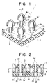
- FIG. 1 is a fragmentary perspective view of a molded surface fastener according to a first embodiment
- FIG. 2 is a cross-sectional view taken along the line I-I of FIG. 1
- FIG. 3 is a cross-sectional view taken along the line II-II of FIG. 2.
- reference numeral 1 designates a molded surface fastener manufactured by injection molding using thermoplastic synthetic resin material.
- This thermoplastic synthetic resin material is exemplified by polyamide resin, polyester resin, polypropylene resin, polyvinyl resin, polystyrene resin and polyurethane resin individually and in combination.
- the molded surface fastener 1 of this invention should have a rational shape.
- the whole of the molded surface fastener 1 is made of the same kind of synthetic resin material.
- the molded surface fastener 1 comprises a substrate sheet 2, a multiplicity of engaging elements 3 arranged on a front surface of the substrate sheet 2 in matrix, and a multiplicity of protuberances 4 arranged on the front surface of the substrate sheet 2 in matrix each at a central position between the front and rear and right and left engaging elements 3.
- the height of the protuberances 4 may be determined as desired, it is required to be such that right before an engaging head 3b described below of the engaging element engages a mating engaging head 3b, a top of each protuberance 4 can project centrally into the individual engaging head 3b of a companion surface fastener of the same structure.
- Each of the engaging elements 3 has a cylindrical stem 3a standing on the front surface of the substrate sheet, and the hemispheric engaging head 3b horizontally bulging from an upper end of the stem 3a.
- the engaging element 3 of the first embodiment is composed of subdivided stems 3a' which are formed by dividing the cylindrical stem 3a as the horizontal cross section is divided into four segments by a predetermined gap of a cross shape, and subdivided heads 3b' which are formed by dividing the substantially hemispheric engaging head 3b, provided on top of each subdivided stems 3a', into four segments.
- the separating surface of the engaging head 3b vertically extend to the front surface of the substrate sheet 2 through the stem 3a.
- the arcuate surface of a base of each subdivided stem 3a' is surrounded by a fan-shaped hole 2a extending radially and through the substrate sheet 2.
- the substrate sheet 2 has in a rear surface of the substrate sheet 2 a multiplicity of through-holes 2b one centrally at the base end of each stem 3a, each through-hole 2b having a circular cross section slightly larger in diameter than a circle tangent to the inner corners of the four subdivided stems 3a'.
- each protuberance 4 projecting from the front surface of the substrate sheet 2 at a central position between the front and rear and right and left engaging elements 3 serves as one example of head-diameter enlarging means that constitutes a part of important elements of this invention.
- the protuberance 4 is in the form of a generally hemisphere molded on the front surface of the substrate sheet 2 simultaneously with the molding of the substrate sheet 2 and the engaging elements 3.
- the protuberance 4 may be a generally conical shape. Namely, as long as it is taper toward its top, the protuberance 4 can enlarge the diameter of the engaging head 3b of the companion surface fastener with it is inserted into the enlarging head 3b.
- the fan-shape hole 2a formed in the substrate sheet 2 and the subdivided head 3b' formed on the upper end of each subdivided stem 3a' have a common projected plane. Assuming that the boundary plane of the stem 3a and the engaging head 3b is a parting line P1 as shown in FIG. 2, the fan-shaped holes 2a and the central through-hole 2b formed centrally of the subdivided stem 3a' are required as derivatives depending on the design of an injection molding die, as a molding expert can readily understand.
- FIG. 4 shows two molded surface fastener 1 of the above-described structure before having been pressed against each other, with their engaging elements 3 in confronting relationship.
- the individual engaging elements 3 of one surface fastener 1 enter between those, arranged in matrix, of the other surface fastener 1 while touching their spheric portions of the engaging heads 3b.
- the four subdivided stems 3a' of each engaging element 3 on one surface fastener 1 are bent inwardly under each other's pressure of the subdivided engaging heads 3b' to reduce the entire diameter of the engaging head 3b so that the engaging heads 3b of one surface fastener 1 can enter between those of the other surface fastener 1 smoothly.
- each protuberance 4 projecting from the substrate sheet 2 of the companion surface fastener is inserted centrally into the four subdivided heads 3b', which are gathered.
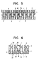
- each protuberance 4 advances further to resilitntly push the four subdivided heads 3b' away from one another to the maximum due to the slope of the protuberance 4 so that the engaging heads 3b can be engaged with those of the companion surface fastener firmly without rattling as shown in FIG. 5.
- the shape of the engaging heads 3b may be modified in order to adjust the peeling force.
- the lower surface of the engaging head 3b may be convex rather than horizontal and flat, bulging downwardly. As the curvature of the arcuate surface is varied, the peeling force can be adjusted.
- FIGS. 6 through 8 show a modification of the first embodiment.
- the molded surface fastener 1 is substantially identical in construction with the first embodiment except that the through-hole 2b of the substrate sheet 2 on the lower side of the base of the stem 3b are omitted. Even without the through-holes 2b, it is possible to accomplish the object of this invention adequately and to facilitate designing the molding die and performing the molding process, thus reducing the cost of projection.
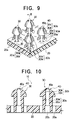
- FIGS. 9 through 11 show a molded surface fastener according to a second embodiment of this invention.
- FIG. 9 is a fragmentary perspective view of the molded surface fastener of the second embodiment
- FIG. 10 is a cross-sectional view taken along the line III-III of FIG. 9
- FIG. 11 is a fragmentary plan view of the molded surface fastener of the second embodiment.
- FIG. 12 is a cross-sectional view showing the molded surface fastener of the second embodiment having been engaged with a companion surface fastener of the same structure.
- This embodiment is differentiated in structure from the first embodiment by the head-diameter enlarging means of the engaging head, leaving the remaining structure substantially similar to that of the first embodiment of FIGS. 1 through 3. Accordingly, parts or elements similar to those of the first embodiment are designated by like reference numerals, and their detailed description is omitted here and the description concentrates on the head-diameter enlarging means.
- a molded surface fastener 10 comprises a substrate sheet 20 integrally molded of synthetic resin material by injection, and a multiplicity of engaging elements 30 each having a stem 30a and an engaging head 30b and arranged in the front surface of the substrate sheet 20 in matrix.
- each engaging element 30 is composed of a set of four subdivided stems 30a' standing upright, four subdivided heads 30b' each having a quarter-hemispheric form radially bulging from the upper end of each subdivided stem 30a', and a bridge 40 extending between tops of the subdivided heads 30b'.
- the subdivided stems 30a' and the subdivided heads 30b' are substantially identical in structure with those of the first embodiment.
- This bridge 40 is a typical example of the head-diameter enlarging means that constitutes a part of important elements of this invention.
- the bridge 40 is in the form of a generally square plate, four corners of which are integrally molded to be connected with the respective upper ends of the four subdivided heads 30b'.
- the bridge 40 were in the form of a generally square flat plate connecting the tops of the subdivided heads 30b', the engaging head 30b could not have been enlarged in diameter. Consequently, in this embodiment, the four side edges of the bridge 40 are inwardly curved, and the center of the bridge 40 is convex upwardly.
- the bridge 40 When a bulged central portion 40a of the bridge 40 is pressed from the upper side to resiliently deform, it must have function to cause the four subdivided stems 30a' to bend radially outwardly by spreading force toward four corners so that the four subdivided heads 30b' are moved away from one another.
- the bridge 40 requires an adequate degree of rigidity, if a specified material is given, it is possible to obtain such rigidity by adjusting the thickness of the bridge 40.
- the bridge 40 has uniform thickness over its entire area.
- the thickness of the bridge 40 may be varied locally or may has a simple cross shape.
- the bulging amount of the bulged central portion 40a of the bridge 40 can be set as desired, it is preferable that the height of the subdivided stem 30a' is set smaller than the total height of the engaging head 30b including the bulging amount of the bulged central portion 40a of the bridge 40 in order that the engaging elements 30 are engaged with those of the companion surface fastener firmly without rattling.
- FIG. 12 shows the engaging elements 30 in engagement when two molded surface fastener 10 of the second embodiment have been pressed to engage. As the two surface fasteners 10 are pressed against each other from their rear sides, with their engaging surfaced facing each other, the individual engaging elements 30 of one surface fastener 10 enter between those, arranged in matrix, of the other surface fastener 10 while touching their arcuate surfaces of the engaging heads 30b.
- the four subdivided stems 30a' of each engaging element 30 on one surface fastener 10 are bent inwardly under each other's pressure of the subdivided engaging heads 30b', and the bridge 40 also is bent to reduce the entire diameter of the engaging head 30b.
- the engaging heads 30b can enter between those of the other surface fastener 10 smoothly.
- the subdivided heads 30b' resiliently restore away from each other so as to restore their original shape, and simultaneously each bridge 40 is pressed downwardly at the bulged central portion 40a by the front surface of the substrate sheet 20 of the companion surface fastener 10 to resiliently deform the bulged central portion 40a to spread flat, and to push the four subdivided heads 30b' away from one another by the reactive force, and further the engaging heads 30b can be engaged with those of the companion surface fastener firmly without rattling as shown in FIG. 12. As a result, it is impossible to separate the joined surface fasteners 10 with a limited peeling force.
- the shape of the engaging heads 30b may be modified likewise the first embodiment, or the thickness of the bridge 40 between the subdivided heads 30b' may be set to be thin. If the same material is given, the smaller the thickness of the bridge 40, the more the bridge 40 will become flexible. As a result, the two molded surface fasteners 10 can be separated relatively easily by the required peeling force.
- the molded surface fastener of this invention partly since at least the engaging head 3b, 30b of each engaging element 3, 30 is expandable and shrinkable in diameter to facilitate engaging the engaging elements 3, 30 with those of the companion surface fastener 1, 10, and partly since the substrate sheet 2, 20 or the individual engaging head 3b, 30b is provided with the head-diameter enlarging means which functions together with the substrate sheet 2, 20 to spread the companion engaging head 3b, 30b in diameter, when the two surface fasteners having generally identical structure are pressed against each other, the engaging heads 3b, 30b are enlarged in diameter by the head-diameter enlarging means and the individual engaging head 3b, 30b is maintained in an expanded posture, thus causing the engaging elements 3, 30 to engage with those of the companion surface fastener firmly without rattling.
Landscapes
- Slide Fasteners, Snap Fasteners, And Hook Fasteners (AREA)
Applications Claiming Priority (2)
| Application Number | Priority Date | Filing Date | Title |
|---|---|---|---|
| JP46036/96 | 1996-03-04 | ||
| JP8046036A JPH09238714A (ja) | 1996-03-04 | 1996-03-04 | 合成樹脂製の一体成形面ファスナー |
Publications (1)
| Publication Number | Publication Date |
|---|---|
| EP0793923A1 true EP0793923A1 (fr) | 1997-09-10 |
Family
ID=12735823
Family Applications (1)
| Application Number | Title | Priority Date | Filing Date |
|---|---|---|---|
| EP97301442A Ceased EP0793923A1 (fr) | 1996-03-04 | 1997-03-04 | Fermeture du type à éléments d'accrochage en matière synthétique réaliséepar moulage |
Country Status (5)
| Country | Link |
|---|---|
| US (1) | US5797170A (fr) |
| EP (1) | EP0793923A1 (fr) |
| JP (1) | JPH09238714A (fr) |
| KR (1) | KR100234928B1 (fr) |
| AU (1) | AU685366B2 (fr) |
Cited By (9)
| Publication number | Priority date | Publication date | Assignee | Title |
|---|---|---|---|---|
| US6076238A (en) * | 1999-04-13 | 2000-06-20 | 3M Innovative Properties Company | Mechanical fastener |
| US6162040A (en) * | 1999-02-01 | 2000-12-19 | Velcro Industries B.V. | Molds for forming touch fasteners |
| US6367128B1 (en) | 2000-02-10 | 2002-04-09 | 3M Innovative Properties Company | Self-mating reclosable mechanical fastener |
| WO2002032248A1 (fr) * | 2000-10-17 | 2002-04-25 | Giuseppe Giordano | Dispositif de fixation et/ou d'assemblage |
| FR2817714A1 (fr) * | 2000-12-07 | 2002-06-14 | Ykk Corp | Fermeture contact moulee d'un seul tenant |
| US6546604B2 (en) | 2000-02-10 | 2003-04-15 | 3M Innovative Properties Company | Self-mating reclosable mechanical fastener and binding strap |
| EP1493348A1 (fr) * | 2003-07-04 | 2005-01-05 | Aplix Société Anonyme | Procédé de fabrication d'autoagrippants à champignons d'accrochage et à boucles ayant une grande durée e vie et dispositifs auto-agrippants obtenus par le procédé |
| WO2005067756A1 (fr) * | 2003-12-23 | 2005-07-28 | 3M Innovative Properties Company | Fermeture a agrafes fendu |
| WO2014153644A1 (fr) * | 2013-03-26 | 2014-10-02 | Astenjohnson, Inc. | Tissu industriel non tissé à interverrouillage mécanique |
Families Citing this family (78)
| Publication number | Priority date | Publication date | Assignee | Title |
|---|---|---|---|---|
| US6303062B1 (en) * | 1999-04-13 | 2001-10-16 | 3M Innovative Properties Company | Mechanical fastener and method for making the same |
| US7246416B2 (en) * | 2000-10-19 | 2007-07-24 | Leonard Arnold Duffy | Slidingly Engagable Fasteners and method |
| GB0106776D0 (en) * | 2001-03-19 | 2001-05-09 | Astenjohnson Inc | Asymmetric tile aperture industrial fabric |
| US6763556B2 (en) * | 2001-09-18 | 2004-07-20 | 3M Innovative Properties Company | Mating film and method for bundling and wrapping |
| US6687962B2 (en) | 2002-01-16 | 2004-02-10 | Velcro Industries B.V. | Fastener element patterning |
| US6662411B2 (en) * | 2002-03-04 | 2003-12-16 | Hewlett-Packard Development Company, L.P. | Mushroom head clip fastener |
| US7207946B2 (en) * | 2002-05-09 | 2007-04-24 | Spiration, Inc. | Automated provision of information related to air evacuation from a chest cavity |
| US20050034213A1 (en) * | 2002-09-28 | 2005-02-17 | Bamber Jeffrey V. | Sports glove |
| US6964063B2 (en) * | 2002-09-28 | 2005-11-15 | Bamber Jeffrey V | Sports glove |
| US6694576B1 (en) * | 2002-10-15 | 2004-02-24 | Ykk Corporation Of America | Fastener strip having vent holes |
| US6944920B2 (en) * | 2002-10-19 | 2005-09-20 | General Motors Corporation | Electrostatically releasable fastening system and method of use |
| US6983517B2 (en) * | 2002-10-19 | 2006-01-10 | General Motors Corporation | Releasable fastener system |
| JP4015983B2 (ja) * | 2002-10-19 | 2007-11-28 | ゼネラル・モーターズ・コーポレーション | 解除可能な付属品用の磁気粘性ナノ複合エラストマー |
| US6973701B2 (en) * | 2002-10-19 | 2005-12-13 | General Motors Corporation | Releasable fastening system based on ionic polymer metal composites and method of use |
| US7013538B2 (en) | 2002-10-19 | 2006-03-21 | General Motors Corporation | Electroactive polymer releasable fastening system and method of use |
| US7140081B2 (en) * | 2002-10-19 | 2006-11-28 | General Motors Corporation | Releasable fastener system |
| US7146690B2 (en) * | 2002-10-19 | 2006-12-12 | General Motors Corporation | Releasable fastener system |
| US7013536B2 (en) | 2002-10-19 | 2006-03-21 | General Motors Corporation | Releasable fastener systems and processes |
| US7308738B2 (en) * | 2002-10-19 | 2007-12-18 | General Motors Corporation | Releasable fastener systems and processes |
| US7032282B2 (en) | 2002-10-19 | 2006-04-25 | General Motors Corporation | Releasable fastener system |
| US7219113B2 (en) * | 2003-09-26 | 2007-05-15 | International Business Machines Corporation | Pseudo-random binary sequence checker with automatic synchronization |
| US7254874B2 (en) * | 2004-03-10 | 2007-08-14 | Leonard Arnold Duffy | Molded surface fasteners and attachment methods |
| US7950114B2 (en) * | 2004-03-10 | 2011-05-31 | Leonard Arnold Duffy | Self-adhering device and method |
| US7340807B2 (en) * | 2005-01-31 | 2008-03-11 | S.C. Johnson Home Storage | Pouch and resealable closure mechanism therefor including a plurality of interlocking closure elements |
| US20060168777A1 (en) * | 2005-01-31 | 2006-08-03 | Turvey Robert R | Slider for a reclosable pouch |
| US7585111B2 (en) * | 2005-01-31 | 2009-09-08 | S.C. Johnson Home Storage, Inc. | Reclosable pouch and closure element therefor having interlocking closure profiles |
| US7316052B2 (en) * | 2005-01-31 | 2008-01-08 | S.C. Johnson Home Storage, Inc. | Closure profile and die plate for extruding same |
| US20060177161A1 (en) * | 2005-01-31 | 2006-08-10 | Turvey Robert R | Pouch having at least one pleat |
| US20060168775A1 (en) * | 2005-01-31 | 2006-08-03 | Turvey Robert R | Closure mechanism including closure profiles having a hollow core |
| US20060216461A1 (en) * | 2005-03-23 | 2006-09-28 | Tachauer Ernesto S | Molding touch fastener elements |
| US7601284B2 (en) * | 2005-04-06 | 2009-10-13 | Velcro Industries B.V. | Molding fastener elements on folded substrate |
| US20060261109A1 (en) * | 2005-05-18 | 2006-11-23 | Browne Alan L | Cargo container including an active material based releasable fastener system |
| US20080002919A1 (en) * | 2006-06-29 | 2008-01-03 | Dais Brian C | Resealable closure mechanism |
| FR2917275A1 (fr) * | 2007-06-13 | 2008-12-19 | Aplix Sa | Dispositif auto-agrippant a crochets a grande souplesse |
| US8225467B2 (en) * | 2007-07-03 | 2012-07-24 | Velcro Industries B.V. | Arrays of fastener elements |
| DE102010032855A1 (de) | 2010-07-30 | 2012-02-02 | Gottlieb Binder Gmbh & Co. Kg | Haftverschlussteil |
| JP4630950B1 (ja) * | 2010-08-19 | 2011-02-09 | 千穂 西 | 接合構造 |
| US9812684B2 (en) | 2010-11-09 | 2017-11-07 | GM Global Technology Operations LLC | Using elastic averaging for alignment of battery stack, fuel cell stack, or other vehicle assembly |
| CN102128193B (zh) * | 2011-03-28 | 2013-05-08 | 鸿富锦精密工业(深圳)有限公司 | 卡扣 |
| US8826499B2 (en) | 2011-06-06 | 2014-09-09 | Nike, Inc. | Closure system |
| US9618026B2 (en) | 2012-08-06 | 2017-04-11 | GM Global Technology Operations LLC | Semi-circular alignment features of an elastic averaging alignment system |
| US9463538B2 (en) | 2012-08-13 | 2016-10-11 | GM Global Technology Operations LLC | Alignment system and method thereof |
| US9556890B2 (en) | 2013-01-31 | 2017-01-31 | GM Global Technology Operations LLC | Elastic alignment assembly for aligning mated components and method of reducing positional variation |
| US9655413B2 (en) | 2013-03-15 | 2017-05-23 | Thomas M. Adams | Self adhering connection surfaces, straps, snaps and bands |
| US9198483B2 (en) * | 2013-03-15 | 2015-12-01 | Thomas M. Adams | Self adhering connection surfaces, straps, snaps and bands |
| US9278642B2 (en) | 2013-04-04 | 2016-03-08 | GM Global Technology Operations LLC | Elastically deformable flange locator arrangement and method of reducing positional variation |
| US9382935B2 (en) | 2013-04-04 | 2016-07-05 | GM Global Technology Operations LLC | Elastic tubular attachment assembly for mating components and method of mating components |
| US9388838B2 (en) | 2013-04-04 | 2016-07-12 | GM Global Technology Operations LLC | Elastic retaining assembly for matable components and method of assembling |
| US9297400B2 (en) | 2013-04-08 | 2016-03-29 | GM Global Technology Operations LLC | Elastic mating assembly and method of elastically assembling matable components |
| US9447840B2 (en) | 2013-06-11 | 2016-09-20 | GM Global Technology Operations LLC | Elastically deformable energy management assembly and method of managing energy absorption |
| US9243655B2 (en) | 2013-06-13 | 2016-01-26 | GM Global Technology Operations LLC | Elastic attachment assembly and method of reducing positional variation and increasing stiffness |
| US9488205B2 (en) | 2013-07-12 | 2016-11-08 | GM Global Technology Operations LLC | Alignment arrangement for mated components and method |
| US9303667B2 (en) | 2013-07-18 | 2016-04-05 | Gm Global Technology Operations, Llc | Lobular elastic tube alignment system for providing precise four-way alignment of components |
| US9458876B2 (en) | 2013-08-28 | 2016-10-04 | GM Global Technology Operations LLC | Elastically deformable alignment fastener and system |
| US9463831B2 (en) | 2013-09-09 | 2016-10-11 | GM Global Technology Operations LLC | Elastic tube alignment and fastening system for providing precise alignment and fastening of components |
| US9457845B2 (en) | 2013-10-02 | 2016-10-04 | GM Global Technology Operations LLC | Lobular elastic tube alignment and retention system for providing precise alignment of components |
| US9511802B2 (en) | 2013-10-03 | 2016-12-06 | GM Global Technology Operations LLC | Elastically averaged alignment systems and methods |
| US9669774B2 (en) * | 2013-10-11 | 2017-06-06 | GM Global Technology Operations LLC | Reconfigurable vehicle interior assembly |
| US9481317B2 (en) | 2013-11-15 | 2016-11-01 | GM Global Technology Operations LLC | Elastically deformable clip and method |
| US9428123B2 (en) | 2013-12-12 | 2016-08-30 | GM Global Technology Operations LLC | Alignment and retention system for a flexible assembly |
| US9447806B2 (en) | 2013-12-12 | 2016-09-20 | GM Global Technology Operations LLC | Self-retaining alignment system for providing precise alignment and retention of components |
| US9216704B2 (en) | 2013-12-17 | 2015-12-22 | GM Global Technology Operations LLC | Elastically averaged strap systems and methods |
| US9446722B2 (en) | 2013-12-19 | 2016-09-20 | GM Global Technology Operations LLC | Elastic averaging alignment member |
| US9599279B2 (en) | 2013-12-19 | 2017-03-21 | GM Global Technology Operations LLC | Elastically deformable module installation assembly |
| US9238488B2 (en) | 2013-12-20 | 2016-01-19 | GM Global Technology Operations LLC | Elastically averaged alignment systems and methods |
| US9541113B2 (en) | 2014-01-09 | 2017-01-10 | GM Global Technology Operations LLC | Elastically averaged alignment systems and methods |
| US9463829B2 (en) | 2014-02-20 | 2016-10-11 | GM Global Technology Operations LLC | Elastically averaged alignment systems and methods |
| US9428046B2 (en) | 2014-04-02 | 2016-08-30 | GM Global Technology Operations LLC | Alignment and retention system for laterally slideably engageable mating components |
| US9657807B2 (en) | 2014-04-23 | 2017-05-23 | GM Global Technology Operations LLC | System for elastically averaging assembly of components |
| US9429176B2 (en) | 2014-06-30 | 2016-08-30 | GM Global Technology Operations LLC | Elastically averaged alignment systems and methods |
| US9758110B2 (en) | 2015-01-12 | 2017-09-12 | GM Global Technology Operations LLC | Coupling system |
| DE102016201263A1 (de) * | 2016-01-28 | 2017-08-03 | Bishop Gmbh | Befestigungssystem |
| JP2017169616A (ja) * | 2016-03-18 | 2017-09-28 | スリーエム イノベイティブ プロパティズ カンパニー | 面ファスナ部材及びその製造方法 |
| US10722003B2 (en) * | 2016-11-23 | 2020-07-28 | Velcro BVBA | Touch fastener |
| JP2019002423A (ja) * | 2017-06-12 | 2019-01-10 | 清水建設株式会社 | 面ファスナ |
| US10238161B1 (en) | 2017-09-28 | 2019-03-26 | League Of Investors, Llc | Adjustable strap for hat |
| DE102017011244A1 (de) * | 2017-12-06 | 2019-06-06 | Gottlieb Binder Gmbh & Co. Kg | Haftverschlusssystem |
| DE102020007585A1 (de) * | 2020-12-11 | 2022-06-15 | Gottlieb Binder Gmbh & Co. Kg | Verschlussteil |
Citations (6)
| Publication number | Priority date | Publication date | Assignee | Title |
|---|---|---|---|---|
| DE1944313A1 (de) * | 1969-09-01 | 1971-03-11 | Oppelt Winfried Prof Dr Ing Dr | Mit Druckmittel arbeitender Verschluss fuer Stoffe,Gewebe und Arbeitsmaterialien |
| US3808648A (en) * | 1970-12-04 | 1974-05-07 | Velcro France | Separable fastening sheet |
| EP0421295A1 (fr) * | 1989-10-03 | 1991-04-10 | Ykk Corporation | Ruban de fermeture du type à élements d'accrochage |
| US5212853A (en) * | 1992-03-10 | 1993-05-25 | Nifco Inc. | Separable plastic fastener and method and apparatus for manufacturing thereof |
| DE9412238U1 (de) * | 1993-07-30 | 1994-12-01 | Minnesota Mining & Mfg | Befestigungsvorrichtung |
| US5396687A (en) * | 1993-11-12 | 1995-03-14 | Osterman; Eric F. | Mechanical fastener |
Family Cites Families (8)
| Publication number | Priority date | Publication date | Assignee | Title |
|---|---|---|---|---|
| US2994117A (en) * | 1958-01-31 | 1961-08-01 | Mcmullin Harold Breniman | Opening closure means |
| US3220078A (en) * | 1963-08-08 | 1965-11-30 | Elastic Stop Nut Corp | Rotary fastener |
| US3292129A (en) * | 1963-10-07 | 1966-12-13 | Grace W R & Co | Silicon thermistors |
| US3416199A (en) * | 1965-06-10 | 1968-12-17 | Minigrip Inc | Seal for bags |
| US3372442A (en) * | 1965-09-18 | 1968-03-12 | High Polymer Chemical Ind Ltd | Synthetic resin fastener |
| FR2577630A1 (fr) * | 1985-02-15 | 1986-08-22 | Touron Roger | Dispositif d'assemblage d'elements en treillis |
| DE3908000A1 (de) * | 1989-03-11 | 1990-09-13 | Achim Rosbach | Vorrichtung zum sichern der verbindung von teilen |
| JPH0584213U (ja) * | 1992-04-24 | 1993-11-16 | 吉田工業株式会社 | 一体成形面ファスナー |
-
1996
- 1996-03-04 JP JP8046036A patent/JPH09238714A/ja active Pending
-
1997
- 1997-02-27 AU AU14991/97A patent/AU685366B2/en not_active Ceased
- 1997-02-28 US US08/807,782 patent/US5797170A/en not_active Expired - Fee Related
- 1997-03-04 KR KR1019970007079A patent/KR100234928B1/ko not_active IP Right Cessation
- 1997-03-04 EP EP97301442A patent/EP0793923A1/fr not_active Ceased
Patent Citations (6)
| Publication number | Priority date | Publication date | Assignee | Title |
|---|---|---|---|---|
| DE1944313A1 (de) * | 1969-09-01 | 1971-03-11 | Oppelt Winfried Prof Dr Ing Dr | Mit Druckmittel arbeitender Verschluss fuer Stoffe,Gewebe und Arbeitsmaterialien |
| US3808648A (en) * | 1970-12-04 | 1974-05-07 | Velcro France | Separable fastening sheet |
| EP0421295A1 (fr) * | 1989-10-03 | 1991-04-10 | Ykk Corporation | Ruban de fermeture du type à élements d'accrochage |
| US5212853A (en) * | 1992-03-10 | 1993-05-25 | Nifco Inc. | Separable plastic fastener and method and apparatus for manufacturing thereof |
| DE9412238U1 (de) * | 1993-07-30 | 1994-12-01 | Minnesota Mining & Mfg | Befestigungsvorrichtung |
| US5396687A (en) * | 1993-11-12 | 1995-03-14 | Osterman; Eric F. | Mechanical fastener |
Cited By (14)
| Publication number | Priority date | Publication date | Assignee | Title |
|---|---|---|---|---|
| US6162040A (en) * | 1999-02-01 | 2000-12-19 | Velcro Industries B.V. | Molds for forming touch fasteners |
| US6076238A (en) * | 1999-04-13 | 2000-06-20 | 3M Innovative Properties Company | Mechanical fastener |
| US6546604B2 (en) | 2000-02-10 | 2003-04-15 | 3M Innovative Properties Company | Self-mating reclosable mechanical fastener and binding strap |
| US6367128B1 (en) | 2000-02-10 | 2002-04-09 | 3M Innovative Properties Company | Self-mating reclosable mechanical fastener |
| US6588074B2 (en) | 2000-02-10 | 2003-07-08 | 3M Innovative Properties Company | Self-mating reclosable binding strap and fastener |
| WO2002032248A1 (fr) * | 2000-10-17 | 2002-04-25 | Giuseppe Giordano | Dispositif de fixation et/ou d'assemblage |
| FR2817714A1 (fr) * | 2000-12-07 | 2002-06-14 | Ykk Corp | Fermeture contact moulee d'un seul tenant |
| EP1493348A1 (fr) * | 2003-07-04 | 2005-01-05 | Aplix Société Anonyme | Procédé de fabrication d'autoagrippants à champignons d'accrochage et à boucles ayant une grande durée e vie et dispositifs auto-agrippants obtenus par le procédé |
| FR2856895A1 (fr) * | 2003-07-04 | 2005-01-07 | Aplix Sa | Dispositifs a champignons d'accrochage et a boucles ayant une grande duree de vie |
| US7120973B2 (en) | 2003-07-04 | 2006-10-17 | Aplix | Method of producing self-fastening systems with hooking mushrooms and loops, having a very long life, and self-fastening systems obtained by the method |
| CN100422574C (zh) * | 2003-07-04 | 2008-10-01 | 埃普利克斯公司 | 生产钩和环型自紧固系统的方法及由其所得的自紧固系统 |
| WO2005067756A1 (fr) * | 2003-12-23 | 2005-07-28 | 3M Innovative Properties Company | Fermeture a agrafes fendu |
| WO2014153644A1 (fr) * | 2013-03-26 | 2014-10-02 | Astenjohnson, Inc. | Tissu industriel non tissé à interverrouillage mécanique |
| US9616638B2 (en) | 2013-03-26 | 2017-04-11 | Astenjohnson, Inc. | Mechanically interlocked nonwoven industrial fabric |
Also Published As
| Publication number | Publication date |
|---|---|
| JPH09238714A (ja) | 1997-09-16 |
| KR970064482A (ko) | 1997-10-13 |
| US5797170A (en) | 1998-08-25 |
| AU685366B2 (en) | 1998-01-15 |
| KR100234928B1 (en) | 1999-12-15 |
| AU1499197A (en) | 1997-09-11 |
Similar Documents
| Publication | Publication Date | Title |
|---|---|---|
| US5797170A (en) | Synthetic resin molded surface fastener | |
| KR920007048Y1 (ko) | 표면형 파스너 | |
| EP1054606B1 (fr) | Elements de fixation, methode et dispositif pour leur fabrication | |
| CA2236516C (fr) | Dispositif d'attache a boutons | |
| US2709290A (en) | Plastic closures | |
| JPH0819406A (ja) | 一体成形面ファスナーの係着片構造 | |
| US8448305B2 (en) | Arrays of fastener elements | |
| GB2364351A (en) | Surface fastener | |
| EP0110350A1 (fr) | Ensemble de bouton pression | |
| JPH10201504A (ja) | 一体成形により得られる面ファスナー用係合部材 | |
| EP0761116A1 (fr) | Fermeture du type à éléments d'accrochage et méthode de fabrication | |
| EP0574863B1 (fr) | Elément de fermeture, du type à éléments d'accrochage réalisé par moulage d'une seule pièce | |
| JPH0584213U (ja) | 一体成形面ファスナー | |
| US5715581A (en) | Hook structure for a molded surface fastener | |
| EP0714614B1 (fr) | Fermeture du type à éléments d'accrochage réalisée par moulage | |
| EP1481603A1 (fr) | Element male de fixation de fermeture adhesive et produit en feuille comportant un tel element de fixation | |
| EP0753278B1 (fr) | Dispositif de fixation pour objet en forme de feuille | |
| US5799378A (en) | Fastening system | |
| EP0292892B1 (fr) | Paire d'éléments s'engageant par emboîtement | |
| EP0465960A1 (fr) | Configuration de tête d'accouplement pour élément de fermeture à glissière | |
| JPH07110017A (ja) | プラスチック製面ファスナ | |
| JPH01250201A (ja) | 面フアスナーの製造方法 | |
| CN1160630A (zh) | 合成树脂模铸的表面扣件 | |
| JP2586918Y2 (ja) | 圧着、剥離型プラスチック製ファスナ | |
| JPS5925211Y2 (ja) | 合成樹脂製ホツク |
Legal Events
| Date | Code | Title | Description |
|---|---|---|---|
| PUAI | Public reference made under article 153(3) epc to a published international application that has entered the european phase |
Free format text: ORIGINAL CODE: 0009012 |
|
| AK | Designated contracting states |
Kind code of ref document: A1 Designated state(s): DE ES FR GB IT |
|
| 17P | Request for examination filed |
Effective date: 19980123 |
|
| GRAG | Despatch of communication of intention to grant |
Free format text: ORIGINAL CODE: EPIDOS AGRA |
|
| 17Q | First examination report despatched |
Effective date: 20010301 |
|
| STAA | Information on the status of an ep patent application or granted ep patent |
Free format text: STATUS: THE APPLICATION HAS BEEN REFUSED |
|
| 18R | Application refused |
Effective date: 20010913 |