EP0793873B1 - Verfahren und vorrichtung zur reduzierung von oberschwingungs-netzrückwirkungen eines selbstgeführten multilevel-wechselrichters - Google Patents
Verfahren und vorrichtung zur reduzierung von oberschwingungs-netzrückwirkungen eines selbstgeführten multilevel-wechselrichters Download PDFInfo
- Publication number
- EP0793873B1 EP0793873B1 EP95936431A EP95936431A EP0793873B1 EP 0793873 B1 EP0793873 B1 EP 0793873B1 EP 95936431 A EP95936431 A EP 95936431A EP 95936431 A EP95936431 A EP 95936431A EP 0793873 B1 EP0793873 B1 EP 0793873B1
- Authority
- EP
- European Patent Office
- Prior art keywords
- multilevel
- invertor
- installation
- inverter
- invertors
- Prior art date
- Legal status (The legal status is an assumption and is not a legal conclusion. Google has not performed a legal analysis and makes no representation as to the accuracy of the status listed.)
- Expired - Lifetime
Links
Images




Classifications
-
- H—ELECTRICITY
- H02—GENERATION; CONVERSION OR DISTRIBUTION OF ELECTRIC POWER
- H02M—APPARATUS FOR CONVERSION BETWEEN AC AND AC, BETWEEN AC AND DC, OR BETWEEN DC AND DC, AND FOR USE WITH MAINS OR SIMILAR POWER SUPPLY SYSTEMS; CONVERSION OF DC OR AC INPUT POWER INTO SURGE OUTPUT POWER; CONTROL OR REGULATION THEREOF
- H02M7/00—Conversion of AC power input into DC power output; Conversion of DC power input into AC power output
- H02M7/42—Conversion of DC power input into AC power output without possibility of reversal
- H02M7/44—Conversion of DC power input into AC power output without possibility of reversal by static converters
- H02M7/48—Conversion of DC power input into AC power output without possibility of reversal by static converters using discharge tubes with control electrode or semiconductor devices with control electrode
- H02M7/483—Converters with outputs that each can have more than two voltages levels
- H02M7/49—Combination of the output voltage waveforms of a plurality of converters
-
- H—ELECTRICITY
- H02—GENERATION; CONVERSION OR DISTRIBUTION OF ELECTRIC POWER
- H02J—ELECTRIC POWER NETWORKS; CIRCUIT ARRANGEMENTS OR SYSTEMS FOR SUPPLYING OR DISTRIBUTING ELECTRIC POWER; SYSTEMS FOR STORING ELECTRIC ENERGY
- H02J3/00—Circuit arrangements for AC mains or AC distribution networks
- H02J3/18—Arrangements for adjusting, eliminating or compensating reactive power in networks
- H02J3/1821—Arrangements for adjusting, eliminating or compensating reactive power in networks using shunt compensators
- H02J3/1835—Arrangements for adjusting, eliminating or compensating reactive power in networks using shunt compensators with stepless control
- H02J3/1842—Arrangements for adjusting, eliminating or compensating reactive power in networks using shunt compensators with stepless control having reactive elements actively controlled by bridge converters, e.g. active filters or static compensators [STATCOM]
- H02J3/1857—Arrangements for adjusting, eliminating or compensating reactive power in networks using shunt compensators with stepless control having reactive elements actively controlled by bridge converters, e.g. active filters or static compensators [STATCOM] the bridge converters being multilevel bridge converters or modular multilevel converters
-
- H—ELECTRICITY
- H02—GENERATION; CONVERSION OR DISTRIBUTION OF ELECTRIC POWER
- H02M—APPARATUS FOR CONVERSION BETWEEN AC AND AC, BETWEEN AC AND DC, OR BETWEEN DC AND DC, AND FOR USE WITH MAINS OR SIMILAR POWER SUPPLY SYSTEMS; CONVERSION OF DC OR AC INPUT POWER INTO SURGE OUTPUT POWER; CONTROL OR REGULATION THEREOF
- H02M1/00—Details of apparatus for conversion
- H02M1/12—Arrangements for reducing harmonics from AC input or output
-
- H—ELECTRICITY
- H02—GENERATION; CONVERSION OR DISTRIBUTION OF ELECTRIC POWER
- H02M—APPARATUS FOR CONVERSION BETWEEN AC AND AC, BETWEEN AC AND DC, OR BETWEEN DC AND DC, AND FOR USE WITH MAINS OR SIMILAR POWER SUPPLY SYSTEMS; CONVERSION OF DC OR AC INPUT POWER INTO SURGE OUTPUT POWER; CONTROL OR REGULATION THEREOF
- H02M7/00—Conversion of AC power input into DC power output; Conversion of DC power input into AC power output
- H02M7/42—Conversion of DC power input into AC power output without possibility of reversal
- H02M7/44—Conversion of DC power input into AC power output without possibility of reversal by static converters
- H02M7/48—Conversion of DC power input into AC power output without possibility of reversal by static converters using discharge tubes with control electrode or semiconductor devices with control electrode
- H02M7/483—Converters with outputs that each can have more than two voltages levels
- H02M7/4835—Converters with outputs that each can have more than two voltages levels comprising two or more cells, each including a switchable capacitor, the capacitors having a nominal charge voltage which corresponds to a given fraction of the input voltage, and the capacitors being selectively connected in series to determine the instantaneous output voltage
-
- H—ELECTRICITY
- H02—GENERATION; CONVERSION OR DISTRIBUTION OF ELECTRIC POWER
- H02M—APPARATUS FOR CONVERSION BETWEEN AC AND AC, BETWEEN AC AND DC, OR BETWEEN DC AND DC, AND FOR USE WITH MAINS OR SIMILAR POWER SUPPLY SYSTEMS; CONVERSION OF DC OR AC INPUT POWER INTO SURGE OUTPUT POWER; CONTROL OR REGULATION THEREOF
- H02M1/00—Details of apparatus for conversion
- H02M1/0095—Hybrid converter topologies, e.g. NPC mixed with flying capacitor, thyristor converter mixed with MMC or charge pump mixed with buck
-
- Y—GENERAL TAGGING OF NEW TECHNOLOGICAL DEVELOPMENTS; GENERAL TAGGING OF CROSS-SECTIONAL TECHNOLOGIES SPANNING OVER SEVERAL SECTIONS OF THE IPC; TECHNICAL SUBJECTS COVERED BY FORMER USPC CROSS-REFERENCE ART COLLECTIONS [XRACs] AND DIGESTS
- Y02—TECHNOLOGIES OR APPLICATIONS FOR MITIGATION OR ADAPTATION AGAINST CLIMATE CHANGE
- Y02E—REDUCTION OF GREENHOUSE GAS [GHG] EMISSIONS, RELATED TO ENERGY GENERATION, TRANSMISSION OR DISTRIBUTION
- Y02E40/00—Technologies for an efficient electrical power generation, transmission or distribution
- Y02E40/20—Active power filtering [APF]
Definitions
- the invention relates to a method for reduction of harmonic network perturbations of a self-guided, fundamental frequency clocked multilevel inverters with capacitive To save.
- this multilevel inverter Through the selection of the switching on and switching off times of the individual Voltage levels of this multilevel inverter can do that Spectrum of the three-phase inverter output voltage to be changed.
- eleven voltage levels of a 12-pulse multilevel inverter the 11th, 13th, 23rd, 25th and 35th harmonics can be suppressed. Consequently is the lowest harmonic, which is then in a three-phase network is delivered, the 37th harmonic.
- Such a multilevel inverter generates an inverter output voltage, which has a certain fundamental vibration content.
- connection voltage also changes of the multilevel inverter.
- a mains current that increased in amplitude and whose temporal course is distorted.
- Such a stream can be used to switch off the multilevel inverter and thus for sudden changes in reactive power in the three-phase network to lead.
- the invention is based on the object of a method and a device for reducing harmonic network perturbations of a self-guided multi-level inverter to indicate with capacitive memories, with which the shown Problem is solved.
- An advantageous method includes angle values and adaptation change values pre-calculated for several working points and saved so that only the new working point in Dependency on determined measured values must be determined. An optimization with regard to several working points takes place off-line instead of.
- the device for performing the method of reduction of harmonic network perturbations of a self-guided Inverter with capacitive storage consists of a device for adjusting the connection voltage this Multilevel inverter to the changed inverter output voltage and a program for the existing one Control and regulating device of the inverter.
- This facility for adjustment is between the three-phase side Outputs of the multilevel inverter and a three-phase network arranged, with a control input and a signal output this device connected to the control and regulating device are.
- the device for Adaptation part of an existing converter transformer In an advantageous device, the device for Adaptation part of an existing converter transformer.
- control and control device each with a memory for the angle values and provided for the adjustment change values. Thereby can by replacing this storage the multilevel inverter customized off-line programming.
- the multilevel inverter system 2 consists of two multilevel inverters 4 and 6, which are linked on the output side by means of a three-phase induction choke circuit 8.
- the three-phase output of the three-phase induction choke circuit 8 is via a device 10 for adapting the connection voltage u '/ R, S, T of the multilevel inverter system 2 to its changeable inverter output voltage u SRR, S, T , which results from the output voltages u R01, S01, T01 or u R02, S02, T02 the multilevel inverters 4 and 6 is composed, linked to a three-phase network 12 to which a further load 14 is connected.
- the inverter system 2 includes a control and regulating device 16, which generates the control signals S 1 ⁇ and S 2 ⁇ for the two multilevel inverters 4 and 6.
- the structure and mode of operation of the multilevel inverter 4 and 6 with capacitive memories 18 and 20 used here is described in detail in an earlier utility model application with the file number G 94 16 048.1.
- the device 10 for adaptation consists, for example, of a transformer 22 and a tap changer 24, which is connected to the control and regulating device 16 via a signal line.
- This control and regulating device 16 generates depending on the status signal S MSt of the tap changer 24 and on current and voltage measured values i R01, S01, T01 , i R02, S02, T02 , i R, S, T , u R01, S01, T01 , U R02, S02, T02 and U R, S, T of the multilevel inverters 4 and 6 and the three-phase network 12 on the one hand the control signals S 1 ⁇ and S 2 ⁇ of the multilevel inverters 4 and 6 and on the other hand an actuating signal S St for the tap changer 24 Device 10.
- this device 16 is provided with two memories 26 and 28 in which, for several operating points of the multilevel inverters 4, 6, m angle values each for connection and disconnection times of the m voltage stages the multilevel inverter 4.6 and a plurality of adaptation change values are stored in each case.
- the angle values and the adaptation change values can be calculated and optimized off-line for different systems.
- FIG. 2 shows a single-phase equivalent circuit diagram of the three-phase device according to FIG. 1.
- the three-phase network 12 is represented by a voltage source 30, which impresses the mains voltage U N.
- the multilevel inverters 4 and 6 are also represented by a voltage source 32, which impresses an inverter output voltage U SR .
- the three-phase induction choke circuit 8 is replaced by an impedance 34, whereas the device 10 is represented by a transformer 36 with adjustable transmission ratio ü.
- the voltage source 32 impresses a voltage U SR for a predetermined operating point.
- the fundamental oscillation of this voltage U SR defines the connection voltage U '/ N of the multilevel inverter system 2, as a result of which the transformation ratio of the transformer 36 is determined.
- the impressing voltages U '/ N and U SR are matched to one another by the choice of the transmission ratio.
- the three-phase connection voltage U '/ N of the inverter system 2 differs from the impressing inverter output voltage U SR by the voltage drop ⁇ U at the impedance 34. If the angle values for the connection and disconnection times of the individual voltage levels of the multilevel inverters 4, 6 are changed, the impressing inverter output voltage U SR also changes .
- the impressing grid voltage U N is constant, so that if the connection voltage U '/ N of the multilevel inverter system 2 is not adapted to the changed impressing inverter output voltage U SR , the grid current I will change in accordance with the changing voltage drop ⁇ U across the impedance 34 changed so that this change in the current I can lead to the shutdown of the multilevel inverters 4, 6.
- the angle values for connection and disconnection times of the individual voltage stages of the multilevel inverters 4, 6 can be changed such that the inverter output voltage U SR is on has optimized harmonic spectrum, and on the other hand the connection voltage U '/ N of this inverter system 2 is adapted to the changed fundamental oscillation amplitude of the inverter output voltage U SR , so that the grid current I changes only insignificantly.
- the harmonic network effects of a self-commutated inverter system 2 can be kept to a minimum for any working points.
- FIG. 3 shows an advantageous embodiment of the inverter system 2.
- Each multilevel inverter 4 and 6 consists of a 6-pulse three-point inverter 38 and two double cascades 40 per phase.
- the double cascades 40 are each provided with switching devices, which are also designed with three points.
- the outputs of the multilevel inverters 4 and 6 are each linked via a circuit breaker 42 to a secondary winding 44 or 46 of a three-winding transformer 48 with the switching group Yyd.
- the primary winding 50 is connected to the three-phase network 12.
- two 6-pulse 11-level inverters 4 and 6 are obtained a 12-pulse 11-level inverter system 2.
- the characteristic harmonics of a 12-pulse inverter system are the 11th, 13th, 23rd, 25th, 35th, 37th, 47th, 49th, ... harmonics.
- Each 11-level inverter 4 and 6 also enables the suppression of five harmonics. This can be used to suppress the 11th, 13th, 23rd, 25th and 35th harmonics.
- the angle values for switching on and switching off times of the eleven voltage stages of the inverters 4 and 6 are determined such that the 11th, 13th, 23rd, 25th and 35th harmonics of the two 6-pulse inverters 4 and 6 are suppressed.
- the inverter output voltage u R01, S01, T01 and u R02, S02, T02 of the two 6-pulse inverters 4 and 6 receives the 5th, 7th, 17th, 19th, 29th, 31st, 37th respectively. , 41st, 43th harmonics.
- the associated mains current i R, S, T is shown in a diagram in FIG. 4 shows the phase-center voltage u R01 and u R02 of phase R of the 11-level inverters 4 and 6.
- the associated phase currents i R01 and i R02 are shown in the diagram in FIG.
- the three-phase inverter output voltages u SRR, S, T which are formed from the output voltages u R01, S01, T01 or u R02, S02, T02 of the multilevel inverters 4 and 6 and are related to the neutral point of the three-phase network 12 shown in the diagram of Figure 6.
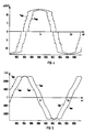
- a 12-pulse 11-level inverter system 2 gives a line current i R, S, T which has the 37th harmonic as the lowest harmonic. If the effort for the multilevel inverter system 2 were to be limited to a 7-level inverter, that is to say there is no double cascade 40 per phase of the multilevel inverters 4 and 6, the grid current i R, S, T is the lowest Harmonic the 25th harmonic.
- the 5th, 7th, 17th, 19th, 29th, 31st, ... harmonics can no longer be used with the three-winding transformer 48 can be deleted with the specified switching group. This means that the failure of a 6-pulse partial inverter 4 or 6 means that the 12-pulse nature of the inverter system 2 is lost. If the control were not changed now, the lowest harmonic in the mains current i R, S, T would now be the 5th harmonic. Thus, the harmonic network feedback of the multilevel inverter system 2 would change abruptly.
- connection voltage u '/ R, S, T of the inverter system 2 is not adapted to the change in the impressing inverter output voltage u SRR, S, T , the inverter system 2 switches off due to an excessive current I.
- the adjustment is carried out with the tap changer 24 of the device 10 or the tap changer 24 is part of the three-winding transformer 48.
- the corresponding control signal S St is calculated by the control and regulating device 16 depending on the actual values present or from a memory 28 which contains pre-calculated values , accessed.
- the actual state of this tap changer 24 is reported to the control and regulating device 16 by means of a state signal S MSt .
- the angle values are also read out from the memory 26.
- the pending actual values are used to determine the new operating points of the inverter 2.
Landscapes
- Engineering & Computer Science (AREA)
- Power Engineering (AREA)
- Inverter Devices (AREA)
Description
- Figur 1
- zeigt ein prinzipielles Blockschaltbild einer ersten Ausführungsform der erfindungsgemäßen Vorrichtung für einen Multilevel-Wechselrichter, die
- Figur 2
- zeigt ein einphasiges Ersatzschaltbild des Blockschaltbildes nach Figur 1, die
- Figur 3
- zeigt eine vorteilhafte Ausführungsform des Multilevel-Wechselrichters, in der
- Figur 4
- sind in einem Diagramm über der Zeit eine Leiter-Mittelpunktspannung der beiden Multilevel-Wechselrichter der Wechselrichteranlage nach Figur 3 dargestellt, wobei in
- Figur 5
- die zugehörigen Ströme in einem Diagramm über der Zeit dargestellt sind, die
- Figur 6
- zeigt in einem Diagramm die Wechselrichter-Ausgangsspannungen bezogen auf den Sternpunkt des Drehstromnetzes und die
- Figuren 7 und 8
- zeigen die Verläufe der Netzströme jeweils in einem Diagramm.
Claims (7)
- Verfahren zur Reduzierung von Oberschwingungs-Netzrückwirkungen einer selbstgeführten, grundfrequenzgetakteten Multilevel-Wechselrichteranlage (2), die zwei Multilevel-Wechselrichter (4,6) mit kapazitiven Speichern (18, 20), einen Transformator (22) und eine Drehstrom-Saugdrosselschaltung (8) aufweist, wobei beim Verlassen eines vorbestimmten Arbeitspunktes dieser Multilevel-Wechselrichteranlage (2) einerseits die Winkelwerte für Zu- und Abschaltzeitpunkte der einzelnen Spannungsstufen der Multilevel-Wechselrichter (4,6) für einen neu bestimmten Arbeitspunkt berechnet werden und andererseits eine Anschlußspannung (u ' / R,S,T) dieser Multilevel-Wechselrichteranlage (2) an eine Änderung der Grundschwingungsamplitude der Wechselrichter-Ausgangsspannung (uSRR,S,T) angepaßt wird.
- Verfahren nach Anspruch 1, wobei vorbestimmte Winkelwerte für verschiedene Arbeitspunkte der Multilevel-Wechselrichteranlage (2) abgespeichert sind, die in Abhängigkeit eines neuen Arbeitspunktes aufgerufen und als Steuersignale (S1ν,S2ν) den Multilevel-Wechselrichtern (4, 6) zugeführt werden.
- Verfahren nach Anspruch 1, wobei vorbestimmte Anpassungsänderungswerte für verschiedene Arbeitspunkte der Multilevel-Wechselrichteranlage (2) abgespeichert sind, die in Abhängigkeit eines neuen arbeitspunktes aufgerufen und als Stellsignal (SSt) einer Einrichtung (10) zur Anpassung der Anschlußspannung (u ' / R,S,T) der Multilevel-Wechselrichteranlage (2) an eine geänderte Grundschwingungsamplitude der Wechselrichter-Ausgangsspannung (uSRR,S,T) zugeführt werden.
- Vorrichtung zur Durchführung des Verfahrens nach Anspruch 1 für eine selbstgeführte, grundfrequenzgetaktete Multilevel-Wechselrichteranlage (2), die zwei Multilevel-Wechselrichter (4,6) mit kapazitiven Speichern (18, 20), einen Transformator (22) und eine Drehstrom-Saugdrosselschaltung (8) aufweist, mit einer Steuer- und Regeleinrichtung (16), die Steuersignale (S1ν ,S2ν) für die Multilevel-Wechselrichter (4, 6) generiert, wobei diese Multilevel-Wechselrichteranlage (2) mittels einer Einrichtung (10) zur Anpassung seiner Anschlußspannung (u ' / R,S,T) mit einem Drehstromnetz (12) verknüpft ist, wobei diese Einrichtung (10) den Transformator (22) und einen Stufenschalter (24) aufweist, wobei die Steuer- und Regeleinrichtung (16) mittels einer Steuerleitung mit diesem Stufenschalter (24) der Einrichtung (10) verknüpft ist und wobei an den Istwert-Eingängen der Steuer- und Regeleinrichtung (16) die Strom- und Spannungs-Istwerte (iR01,S01,T01, iR02,S02,T02, iR,S,T, uR01,S01,T01, uR02,S02,T02, uR,S,T) der Multilevel-Wechselrichter (4,6) und des Drehstromnetzes (12) und ein Zustandssignal (SMSt) der Einrichtung (10) zur Anpassung anstehen.
- Vorrichtung nach Anspruch 4, wobei die Steuer- und Regeleinrichtung (16) mit einem Speicher (26) mit vorbestimmten Winkelwerten für verschiedene Arbeitspunkte versehen ist.
- Vorrichtung nach Anspruch 4, wobei die steuer- und Regeleinrichtung (16) mit einem Speicher (28) mit Anpassungsänderungswerten für verschieden Arbeitspunkte versehen ist.
- Vorrichtung nach Anspruch 4, wobei der Stufenschalter (24) der Einrichtung (10) zur Anpassung Bestandteil eines Dreiwicklungstransformators (48) ist, dessen Sekundärwicklungen (44,46) jeweils mit den Ausgängen der Multilevel-Wechselrichter (4,6) und dessen Primärwicklung (50) mit dem Drehstromnetz (12) verknüpft sind.
Applications Claiming Priority (3)
| Application Number | Priority Date | Filing Date | Title |
|---|---|---|---|
| DE4441758A DE4441758A1 (de) | 1994-11-23 | 1994-11-23 | Verfahren und Vorrichtung zur Reduzierung von Oberschwingungs-Netzrückwirkungen eines selbstgeführten Multilevel-Wechselrichters |
| DE4441758 | 1994-11-23 | ||
| PCT/DE1995/001557 WO1996016469A1 (de) | 1994-11-23 | 1995-11-10 | Verfahren und vorrichtung zur reduzierung von oberschwingungs-netzrückwirkungen eines selbstgeführten multilevel-wechselrichters |
Publications (2)
| Publication Number | Publication Date |
|---|---|
| EP0793873A1 EP0793873A1 (de) | 1997-09-10 |
| EP0793873B1 true EP0793873B1 (de) | 1998-06-03 |
Family
ID=6533990
Family Applications (1)
| Application Number | Title | Priority Date | Filing Date |
|---|---|---|---|
| EP95936431A Expired - Lifetime EP0793873B1 (de) | 1994-11-23 | 1995-11-10 | Verfahren und vorrichtung zur reduzierung von oberschwingungs-netzrückwirkungen eines selbstgeführten multilevel-wechselrichters |
Country Status (4)
| Country | Link |
|---|---|
| US (1) | US5889662A (de) |
| EP (1) | EP0793873B1 (de) |
| DE (2) | DE4441758A1 (de) |
| WO (1) | WO1996016469A1 (de) |
Families Citing this family (10)
| Publication number | Priority date | Publication date | Assignee | Title |
|---|---|---|---|---|
| GB2327818B (en) * | 1997-07-29 | 2001-10-17 | Gec Alsthom Ltd | Switching control arrangement |
| ATE252576T1 (de) | 1999-12-03 | 2003-11-15 | Pfizer Prod Inc | Heteroarylphenylpyrazolverbindungen zur verwendung als analgetisches/entzündungshemmendes mittel |
| GB0007921D0 (en) * | 2000-03-31 | 2000-05-17 | Nordson Corp | Power factor corrector |
| JP2004253772A (ja) * | 2003-01-31 | 2004-09-09 | Matsushita Electric Ind Co Ltd | 半導体集積回路装置 |
| US20070230226A1 (en) * | 2003-11-25 | 2007-10-04 | Jih-Sheng Lai | Multilevel intelligent universal auto-transformer |
| US6954366B2 (en) * | 2003-11-25 | 2005-10-11 | Electric Power Research Institute | Multifunction hybrid intelligent universal transformer |
| US7050311B2 (en) * | 2003-11-25 | 2006-05-23 | Electric Power Research Institute, Inc. | Multilevel converter based intelligent universal transformer |
| US20070223258A1 (en) * | 2003-11-25 | 2007-09-27 | Jih-Sheng Lai | Multilevel converters for intelligent high-voltage transformers |
| FR3060906B1 (fr) * | 2016-12-16 | 2019-05-24 | Ge Energy Power Conversion Technology Limited | Convertisseur continu-alternatif |
| US11159021B2 (en) * | 2017-05-02 | 2021-10-26 | Siemens Energy Global GmbH & Co. KG | Flexible reactive power compensation |
Family Cites Families (14)
| Publication number | Priority date | Publication date | Assignee | Title |
|---|---|---|---|---|
| US3979662A (en) * | 1975-05-05 | 1976-09-07 | Eaton Corporation | Paralleling of inverters for low harmonics |
| JPS6040254B2 (ja) * | 1978-06-14 | 1985-09-10 | 株式会社日立製作所 | 無効電力制御装置 |
| US4204264A (en) * | 1978-11-27 | 1980-05-20 | United Technologies Corporation | Harmonic cancellation for multi-bridge, three-phase converters |
| CS215272B1 (en) * | 1979-01-02 | 1982-08-27 | Jiri Winkler | Connection of the current alternator with proper commutation |
| US4344123A (en) * | 1981-09-14 | 1982-08-10 | Canadian Patents & Development Limited | Multilevel PWM inverter |
| DE3907940A1 (de) * | 1988-05-05 | 1989-11-16 | Asea Brown Boveri | Verfahren zur symmetrierung der spannungsaufteilung an stromrichtern mit mehrpunktschaltung |
| US5040105A (en) * | 1989-12-20 | 1991-08-13 | Sundstrand Corporation | Stepped-waveform inverter with eight subinverters |
| US5065303A (en) * | 1990-07-24 | 1991-11-12 | Sundstrand Corporation | Transformer-coupled and phase-shifted inverter |
| US5155672A (en) * | 1990-08-09 | 1992-10-13 | Heart Interface Corporation | Switched multi-tapped transformer power conversion method and apparatus |
| US5138544A (en) * | 1991-04-02 | 1992-08-11 | Westinghouse Electric Corp. | Harmonically modified twelve-pole inverter |
| DE4207971A1 (de) * | 1992-03-13 | 1993-09-16 | Numatics Gmbh | Steuerzylinder fuer pneumatische steuergeraete mit signalkontakten |
| DE4225269A1 (de) * | 1992-07-31 | 1994-02-03 | Asea Brown Boveri | Verfahren zur Dämpfung von Netzoberschwingungen und eine Netzkupplung |
| US5339235A (en) * | 1993-05-11 | 1994-08-16 | Alliedsignal Inc. | Fault compensating multi-step wave inverter |
| DE9416048U1 (de) * | 1994-10-06 | 1996-02-01 | Siemens Ag | Vorrichtung zur Erhöhung der Grundschwingungs-Leistungsausbeute eines selbstgeführten Wechselrichters |
-
1994
- 1994-11-23 DE DE4441758A patent/DE4441758A1/de not_active Withdrawn
-
1995
- 1995-11-10 WO PCT/DE1995/001557 patent/WO1996016469A1/de not_active Ceased
- 1995-11-10 DE DE59502440T patent/DE59502440D1/de not_active Expired - Lifetime
- 1995-11-10 EP EP95936431A patent/EP0793873B1/de not_active Expired - Lifetime
-
1997
- 1997-05-23 US US08/862,207 patent/US5889662A/en not_active Expired - Lifetime
Also Published As
| Publication number | Publication date |
|---|---|
| DE59502440D1 (de) | 1998-07-09 |
| EP0793873A1 (de) | 1997-09-10 |
| US5889662A (en) | 1999-03-30 |
| DE4441758A1 (de) | 1996-05-30 |
| HK1001803A1 (en) | 1998-07-10 |
| WO1996016469A1 (de) | 1996-05-30 |
Similar Documents
| Publication | Publication Date | Title |
|---|---|---|
| DE69611176T2 (de) | Verfahren und vorrichtung für die stufenlose einstellung und regulierung des windungsverhältnises eines transformatores und transformator mit einer solchen vorrichtung | |
| EP3172823B1 (de) | Gleichspannungswandler mit transformator | |
| DE69206020T2 (de) | Speiseschaltung. | |
| EP0152002B1 (de) | Phasenschieber | |
| DE3608704A1 (de) | Spannungsspitzen freier festkoerperschalter und einrichtung zur automatischen leistungsfaktor-korrektur | |
| EP0254911B1 (de) | Stromrichterschaltung und Verfahren zu dessen Steuerung | |
| DE10153738B4 (de) | Gleichrichterschaltung und Verfahren zu deren Steuerung | |
| EP1589647A2 (de) | Strom-Spannungsregler und zugehöriger Regelkreis | |
| DE4441758A1 (de) | Verfahren und Vorrichtung zur Reduzierung von Oberschwingungs-Netzrückwirkungen eines selbstgeführten Multilevel-Wechselrichters | |
| DE2937262A1 (de) | Blindleistungsgenerator | |
| DE2605185C3 (de) | Einphasen-Stromrichter | |
| EP3327912A1 (de) | Hystereseregelung eines ausgangsstroms eines stromrichters | |
| CH641610A5 (de) | Rundsteueranlage. | |
| DE102019105196B4 (de) | Verfahren zur Strombegrenzung bei transienten Spannungsänderungen an einem Wechselstromausgang eines Multilevel-Wechselrichters und Multilevel-Wechselrichter | |
| DE19605419B4 (de) | Verfahren zur Beseitigung von Abweichungen der Ist-Spannung in einem Drehstromnetz von einer vorgegebenen Soll-Spannung | |
| EP3118961B1 (de) | Nutzung elektrischer netz-verzerrungsenergie mittels gleichrichter | |
| EP1398867B1 (de) | Vorrichtung zur Spannungserhaltung eines elektrischen Wechselspannungsnetzes sowie Verfahren zum Betrieb einer solchen Vorrichtung | |
| DE4446864A1 (de) | Abschaltverfahren für einen dreiphasigen Blindleistungssteller mit zwei Thyristorschaltern | |
| AT410184B (de) | Antriebseinrichtung für walzgerüste | |
| EP2849327B1 (de) | Variabler Tiefsetzer und Batterieladestation mit einem solchen Tiefsetzer | |
| WO2004001778A1 (de) | Schaltungsanordnung zur erzeugung einer röntgenröhrenspannung | |
| EP0737333B1 (de) | Konstantstromregler mit aufspanntransformator | |
| EP1870996A1 (de) | Schaltung zum Einspeisen elektrischer Energie in ein elektrisches Versorgungsnetz | |
| DE4036062C2 (de) | Netzteil mit geregelter Ausgangsspannung | |
| AT397321B (de) | Schaltungsanordnung bei einem gesteuerten stromrichter |
Legal Events
| Date | Code | Title | Description |
|---|---|---|---|
| PUAI | Public reference made under article 153(3) epc to a published international application that has entered the european phase |
Free format text: ORIGINAL CODE: 0009012 |
|
| 17P | Request for examination filed |
Effective date: 19970520 |
|
| AK | Designated contracting states |
Kind code of ref document: A1 Designated state(s): DE FR GB |
|
| GRAG | Despatch of communication of intention to grant |
Free format text: ORIGINAL CODE: EPIDOS AGRA |
|
| 17Q | First examination report despatched |
Effective date: 19970926 |
|
| GRAG | Despatch of communication of intention to grant |
Free format text: ORIGINAL CODE: EPIDOS AGRA |
|
| GRAH | Despatch of communication of intention to grant a patent |
Free format text: ORIGINAL CODE: EPIDOS IGRA |
|
| GRAH | Despatch of communication of intention to grant a patent |
Free format text: ORIGINAL CODE: EPIDOS IGRA |
|
| GRAA | (expected) grant |
Free format text: ORIGINAL CODE: 0009210 |
|
| AK | Designated contracting states |
Kind code of ref document: B1 Designated state(s): DE FR GB |
|
| REF | Corresponds to: |
Ref document number: 59502440 Country of ref document: DE Date of ref document: 19980709 |
|
| ET | Fr: translation filed | ||
| GBT | Gb: translation of ep patent filed (gb section 77(6)(a)/1977) |
Effective date: 19980807 |
|
| PLBE | No opposition filed within time limit |
Free format text: ORIGINAL CODE: 0009261 |
|
| STAA | Information on the status of an ep patent application or granted ep patent |
Free format text: STATUS: NO OPPOSITION FILED WITHIN TIME LIMIT |
|
| 26N | No opposition filed | ||
| REG | Reference to a national code |
Ref country code: GB Ref legal event code: IF02 |
|
| PGFP | Annual fee paid to national office [announced via postgrant information from national office to epo] |
Ref country code: FR Payment date: 20101130 Year of fee payment: 16 |
|
| PGFP | Annual fee paid to national office [announced via postgrant information from national office to epo] |
Ref country code: GB Payment date: 20101111 Year of fee payment: 16 |
|
| PGFP | Annual fee paid to national office [announced via postgrant information from national office to epo] |
Ref country code: DE Payment date: 20110121 Year of fee payment: 16 |
|
| GBPC | Gb: european patent ceased through non-payment of renewal fee |
Effective date: 20111110 |
|
| REG | Reference to a national code |
Ref country code: FR Ref legal event code: ST Effective date: 20120731 |
|
| REG | Reference to a national code |
Ref country code: DE Ref legal event code: R119 Ref document number: 59502440 Country of ref document: DE Effective date: 20120601 |
|
| PG25 | Lapsed in a contracting state [announced via postgrant information from national office to epo] |
Ref country code: GB Free format text: LAPSE BECAUSE OF NON-PAYMENT OF DUE FEES Effective date: 20111110 |
|
| PG25 | Lapsed in a contracting state [announced via postgrant information from national office to epo] |
Ref country code: FR Free format text: LAPSE BECAUSE OF NON-PAYMENT OF DUE FEES Effective date: 20111130 |
|
| PG25 | Lapsed in a contracting state [announced via postgrant information from national office to epo] |
Ref country code: DE Free format text: LAPSE BECAUSE OF NON-PAYMENT OF DUE FEES Effective date: 20120601 |