EP0792015A2 - Funkrufempfänger mit Signalpegelregelung - Google Patents
Funkrufempfänger mit Signalpegelregelung Download PDFInfo
- Publication number
- EP0792015A2 EP0792015A2 EP97103029A EP97103029A EP0792015A2 EP 0792015 A2 EP0792015 A2 EP 0792015A2 EP 97103029 A EP97103029 A EP 97103029A EP 97103029 A EP97103029 A EP 97103029A EP 0792015 A2 EP0792015 A2 EP 0792015A2
- Authority
- EP
- European Patent Office
- Prior art keywords
- signal
- radio
- radio signal
- receiving
- sync
- Prior art date
- Legal status (The legal status is an assumption and is not a legal conclusion. Google has not performed a legal analysis and makes no representation as to the accuracy of the status listed.)
- Withdrawn
Links
Images


Classifications
-
- H—ELECTRICITY
- H04—ELECTRIC COMMUNICATION TECHNIQUE
- H04W—WIRELESS COMMUNICATION NETWORKS
- H04W52/00—Power management, e.g. Transmission Power Control [TPC] or power classes
- H04W52/02—Power saving arrangements
- H04W52/0209—Power saving arrangements in terminal devices
- H04W52/0261—Power saving arrangements in terminal devices managing power supply demand, e.g. depending on battery level
-
- H—ELECTRICITY
- H03—ELECTRONIC CIRCUITRY
- H03G—CONTROL OF AMPLIFICATION
- H03G3/00—Gain control in amplifiers or frequency changers
- H03G3/20—Automatic control
- H03G3/30—Automatic control in amplifiers having semiconductor devices
- H03G3/3052—Automatic control in amplifiers having semiconductor devices in bandpass amplifiers (H.F. or I.F.) or in frequency-changers used in a (super)heterodyne receiver
- H03G3/3057—Automatic control in amplifiers having semiconductor devices in bandpass amplifiers (H.F. or I.F.) or in frequency-changers used in a (super)heterodyne receiver using at least one diode as controlling device
-
- H—ELECTRICITY
- H04—ELECTRIC COMMUNICATION TECHNIQUE
- H04W—WIRELESS COMMUNICATION NETWORKS
- H04W88/00—Devices specially adapted for wireless communication networks, e.g. terminals, base stations or access point devices
- H04W88/02—Terminal devices
- H04W88/022—Selective call receivers
Definitions
- the present invention relates to a radio selective call receiver, and more particularly to a radio selective call receiver for receiving a radio signal of a signal format having a plurality of sync signals in one frame.
- a first technique lowers a level of a radio signal to prolong a preamble search mode when a bit synchronization can not be achieved due to the interfering nave.
- a second technique lowers a level of the radio signal received according to the receive synchronization enabled/disabled state.
- the radio selective call receiver in the first technique is disclosed in, for example, U.S. patent application Serial No. 08/365434 (Japanese laid-open patent application heisei 5-336605).
- a controller turns on an attenuation circuit to increase a number of bits of a preamble search mode by a predetermined number if the controller can not achieve the bit synchronization and determines that the interfering wave is generated from an output of a comparator.
- the attenuation circuit is turned on, a level of the radio signal is attenuated, improving the receiving rate.
- a decoder detects a frame-sync signal and a group-sync signal from a received signal, thereby achieving the receive synchronization. If at least either the frame-sync signal or the group-sync signal is not detected, the decoder outputs a control signal.
- a gain control circuit controls gain allocation of the received signal based on the control signal from the decoder.
- An object of the present invention is to provide an improved radio selective call receiver free from the above-described drawbacks.
- the radio selective call receiver has a controller which judges whether reception of a first sync signal is enabled from the radio signal having a plurality of sync signals and outputs a control signal "L" to an attenuation circuit with a timing at which a second sync signal is received to lower the radio signal level when judged that reception of the first sync signal is disabled.
- the judgment upon whether reception of the first sync signal is enabled is preferably performed using a base band signal demodulated in a demodulator and a result of comparing a direct current voltage relative to an electric field intensity level of the radio signal with a predetermined voltage in a comparator.
- the controller detects a second sync signal and informs that a call number in a self-frame has been received using an informing section at the time of receiving that call number, thereby displaying a message on a display section.
- the control signal "L" is output to the attenuation circuit to lower the level of the radio signal which may serve as the interfering wave with a timing at which the attenuation circuit receives the second sync signal.
- the present invention therefore lowers the level of the radio signal with a timing at which the second sync signal is received when determined that reception of the first sync signal is disabled, which can improve the receiving ratio and prevent the receiving opportunity from being lost by receiving a call number in the same frame.
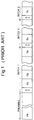
- a signal transfer format applied to the radio selective call receiver is constituted by a preamble signal PA and a plurality of batch signals following the preamble signal PA.
- Each batch signal is formed by sequentially arranging a sync-code word SC and eight frames G1 to G8.
- a radio signal received by an antenna 21 is input to an amplifier 23 in this radio selective call receiver.
- the radio signal amplified in the amplifier 23 is converted into a base band signal in a demodulator 24.
- a received signal level detector 25 outputs a direct current voltage according to a level of the radio signal amplified by the amplifier 23.
- a comparator 26 compares the direct current voltage output from the received signal level detector 25 with a predetermined voltage to output a receive electric field level to a controller 27.
- the controller 27 judges upon whether bit synchronization is achieved by the base band signal from the demodulator 24.
- the controller 27 If the controller 27 can not attain bit synchronization and an output from the comparator 26 corresponds to "High", namely, the direct current voltage output by the received signal level detector 25 is larger than the predetermined voltage, the controller 27 turns on a radio signal attenuation circuit 22 to increase a number of bits of the preamble search mode by a. A number of bits of the preamble search mode returns to its original number when a predetermined time lapses. In this manner, when the signal of its own group is confirmed and a call number coincides with its own call number, informing sections 28 to 31 inform of a carrier of the receiver that effect.
- each subframe is constituted by sequentially arranging a common frame-sync signal FC, a group-sync signal GC inherent to each sub-frame, and a plurality of radio selective call numbers #1 to #6.
- a radio signal received by an antenna 1 is amplified in a receiver 2 with a predetermined gain and thereafter demodulated.
- the demodulated signal is converted into a digital data signal by a waveform shaping circuit 3.
- a decoder 4 detects a frame-sync signal FC and a group-sync signal GC from the data signal output from the waveform shaping circuit 3 to establish receive synchronization.
- reception of the radio selective call numbers #1 to #6 is allowed.
- Each of the received radio selective call numbers is compared with its own selective call number previously recorded in a P-ROM 5.
- the decoder 4 When these numbers have coincided with each other, the decoder 4 outputs an alert signal to an amplifier 6 to generate sound from a speaker 7. In addition, when the decoder 4 can not detect at least either the frame-sync signal FC or the group-sync signal GC, an ON control signal and an OFF control signal are output in accordance with a number of times that no detection was made.
- a gain control circuit 11 controls the gain allocation of the radio signal input to the receiver 2 based on the ON control signal and the OFF control signal output from the decoder 4. When the decoder 4 can not sequentially detect the frame-sync signals FC and the group-sync signals GC for a predetermined number of times, reception of the radio selective call numbers #1 to #6 is prohibited.
- the gain allocation of the radio signal input to the receiver is changed in a second frame. In other words, a call is impossible in the first frame, but receiving at least the second frame enables the call. Since the call is disabled in the first frame, the receiving opportunity is therefore lost.
- the present invention decreases the loss of the receiving opportunity and rapidly calls a user on the remote side by providing a plurality of sync signals in each frame, lowering the level of the radio signal when a first sync signal was not detected and detecting a second sync signal in the same frame to make a call.
- the radio selective call receiver according to the present invention adopts the binary FSK (frequency shift keying) modulation or the quadrature FSK modulation, and one cycle is made up of 16 frames F1 to F16.
- one frame is constituted by sequentially arranging a sync signal 1, a sync signal 2, addresses A1 to An, messages M1 to Mn. Each address consists of address information and a vector.
- the vector indicates a position of a message relative to address information to be called or a position where the message starts.
- each of the sync signals 1 and 2 according to the present invention is composed of 32 bits.
- the sync signal 1 corresponds to "1011" and the sync signal 2 to "10111".
- the sync signals 1 and 2 are detected by confirming whether their bit strings coincide with a predetermined bit string.
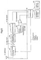
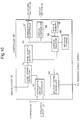
- the radio selective call receiver includes a receiver 41, a controller 42, an informing section 43, and a display section 44.
- the receiver 41 is provided with an antenna 51, an attenuation circuit 52, an amplifier 53, a frequency converter 54, a demodulator 55, a level detector 56 and a comparator 57.
- the receiver 41 receives the radio signal having the signal format shown in Fig. 5 and fed from a non-illustrated base station by the antenna 51.
- the attenuation circuit 52 lowers the level of the radio signal using a control signal "L" from the controller 42 which will be described later.
- the amplifier 53 amplifies the radio signal.
- the frequency converter 54 shifts the frequency of the radio signal amplified in the amplifier 53 to a first frequency band and a second frequency band.
- the demodulator 55 demodulates the radio signal shifted to the second frequency band by the frequency converter 54 into a base band signal.
- the level detector 56 outputs a direct current voltage corresponding with an electric field intensity level of the radio signal shifted to the second frequency band by the frequency converter 54.
- the comparator 57 compares the direct current voltage output by the level detector 56 with a predetermined voltage. If the direct current voltage output by the level detector 56 is larger than a predetermined voltage, the comparator 57 outputs a receive electric field level "H".
- the controller 42 judges whether the first sync signal can be received by using the base band signal demodulated by the demodulator 55. When it has been determined that the first sync signal can not be received due to intermodulation of the interfering wave based on the receive electric field level output from the comparator 57, a control signal "L" is output to the attenuation circuit 52 to lower the level of the radio signal that may serve as the interfering wave with a timing at which the second sync signal is received. When the second sync signal was received, an address and a message in the same frame are received.
- the informing section 43 informs that a call number of its own radio selective call receiver was received.
- the informing section 43 may be preferably constituted by a speaker, a LED, a vibrator or the like.
- the display section 44 displays the received message.
- the display section 44 may be preferably constituted by a cathode ray tube (CRT), a liquid crystal display (LCD) or the like.
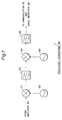
- the frequency converter 54 is provided with a first mixer 61, a first local oscillator 62, a first band pass filter (BPF) 63, a second mixer 64, a second local oscillator 65 and a second BPF 66.
- BPF band pass filter
- the radio signal amplified by the amplifier 53 is shifted to a first IF frequency band based on an output from the first local oscillator 62 in the first mixer 61.
- the radio signal shifted to the first IF frequency band is further shifted to the second frequency band based on an output from the second local oscillator 65 in the second mixer 64 through the first BPF 63.
- the radio signal shifted to the second frequency band is output to the demodulator 55 through the second BPF 66.
- the demodulator 55 includes a limiter 71, a discriminator 72, a LPF 73 and a waveform shaper 74.
- the radio signal shifted to the second frequency band and amplified to a desired level in the frequency converter 54 is amplitude-limited in the limiter 71 for FM detection.
- the radio signal is thereafter subjected to frequency-to-voltage conversion to be demodulated in the discriminator 72.
- the demodulated signal demodulated in the discriminator 72 has noise component outside the desired frequency band which is removed in the LPF 73 and is shaped into a rectangular wave in the waveform shaper 74 to be output to a controller 42 as a digital signal.
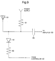
- the attenuation circuit 52 is provided with a first resistor 81, a diode 82, a second resistor 83 and a capacitor 84.
- the diode 82 does not become conductive because of no difference in potential between both ends thereof, and the radio signal input from the antenna 51 is input to the amplifier 53 through the capacitor 84 that separates the amplifier 53 from the antenna 51 in terms of direct current. If the control signal output from the controller 42 is "L”, the diode 82 becomes conductive because the power supply voltage is applied to an anode of the diode 82 and the current limited by the first resistor 81 and the second resistor 83 flows. When the diode is conductive, the level of he radio signal input from the antenna 51 is lowered.
- the controller 42 is provided with a sync signal 1 detector 91, a sync signal 2 detector 92, an attenuation circuit controller 93, a battery saving controller 94, an address collator 95, a message storing section 96, an annunciation controller 97, a display controller 98 and a self-ID memory 99.
- the sync signal 1 detector 91 Based on the base band signal output from the demodulator 55, the sync signal 1 detector 91 makes judgment upon whether the sync signal 1 has been detected. When the sync signal 1 has not been detected, the attenuation circuit controller 93 judges whether the receive electric field level output from the comparator 57 is "H”. When the receive electric field level output from the comparator 57 is "H”, the attenuation circuit controller 93 outputs a control signal "L" to the attenuation circuit 52 to lower the level of the radio signal.
- the sync signal 2 detector 92 judges whether the sync signal 2 has been detected.
- the address collator 95 compares the address in the self-frame with the self-address stored in the self-ID memory 99.
- the received message is temporarily stored in the message storing section 96.
- the informing section 43 is used to inform that the radio selective call receiver has received its own call number through the annunciation controller 97, and the display section 44 displays the received message through the display controller 98.
- the battery saving controller 94 turns off the power supply after detection of the sync signal 2 and again turns on the power supply in the self-frame.
- the battery saving operation is not the important point in the present invention, thereby omitting the explanation thereof.
- the controller 42 turns off the attenuation circuit 52 as an initialized state (S101).
- the controller 42 judges whether the first sync signal, i.e., the sync signal 1 has been detected based on the based band signal output from the demodulator 55 (S102).
- the controller 42 judges whether the second sync signal, i.e., the sync signal 2 has been detected (S105).
- the controller 42 confirms a signal for identifying the self-frame (S106).
- the controller 42 receives its own call number in the self-frame (S107).
- the controller 42 outputs information representing the success of reception to the informing section 43 to carry out the infoming operation (S108).
- the controller 42 displays the received message on the display section 44 (S109) and returns to the initialized state (S101).
- the controller 42 When the controller 42 has failed to detect the sync signal 2 (NO in S105), when the controller 42 has failed to confirm the signal for identifying the self-frame (NO in S106), or when the controller 42 has failed to receive its own call number (NO in S107), the controller 42 terminates the receiving operation to return to the initialised state, thereby restarting the receiving operation (S101).
- the controller 42 judges whether the receive electric field level output from the comparator 57 is "H" (S103).
- the controller 42 terminates the receiving operation to return to the initialized state and restarts the receiving operation (S101).
- the controller 42 determines that the sync signal 1 is not received due to the interfering wave and outputs the control signal "L” to the attenuation circuit 52 to turn on the attenuation circuit 52 (S104).
- the controller 42 judges whether the second sync signal, i.e., the sync signal 2 has been detected (S105). If the controller 42 has detected the sync signal 2 (YES in S105), the controller 42 confirms the signal for identifying the self-frame (S106). If the controller 42 has confirmed the signal for identifying the self-frame (YES in S106), the controller 42 receives its own call number in the self-frame (S107). If the controller 42 has received its own call number (YES in S107), the controller 42 outputs information representing the success of reception to the informing section 43 to perform the informing operation (S108). At the same time, the controller 42 displays the received message on the display section 44 (S109) and returns to the initialized state (S101).
- the controller 42 displays the received message on the display section 44 (S109) and returns to the initialized state (S101).
- controller 42 If the controller 42 has failed to detect the sync signal 2 (NO in S105), if the controller 42 has failed to confirm the signal for identifying the self-frame (NO in S106) or if the controller 42 has failed to receive its own call number (NO in S107), the controller terminates the receiving operation to return to the initialized state, thereby restarting the receiving operation (S101).
- an address A2 corresponds to the self-frame in the radio selective call receiver according to the present invention.
- the receiver power supply is turned on when detecting the sync signal 1 and the sync signal 2, and turned off after detecting the sync signal 2. Subsequently, the receiver power supply is again turned on in the address A2 that is the self-frame, and turned off at the end of the address A2. In a message M1, the receiver power supply is again turned on and remains to be on until the sync signal is detected in the next frame.
- the controller 42 If the output from the comparator 57 is "H" when the sync signal 1 was not detected, it is determined that the sync signal can not be received due to the interfering wave, and the controller 42 outputs the control signal "L” before the sync signal 2.
- the control signal "L” output from the controller 42 is used to turn on the attenuation circuit 52 in order to lower the receive electric field level of the radio signal.
- the output from the comparator 57 becomes "L", which enables reception of the sync signal 2.
- the address A2 is confirmed and a message M2 is received.
- the radio selective call receiver since the radio selective call receiver according to the present invention lowers the level of the radio signal with a timing at which the second sync signal is received when determined that the first sync signal can not be received, the receiving ratio can be increased, and receiving the call number in the same frame can prevent the receiving opportunity from being lost.
- each of the sync signals 1 and 2 in the frame consists of 32 bits in the foregoing embodiment, the present invention is not restricted to a certain number of bits constituting each of the sync signals 1 and 2 in the frame, and a number of bits constituting the sync signal 1 does not have to be the same with that constituting the sync signal 2. Further, each of the sync signals 1 and 2 may be the same.
- the present invention has described the characteristic of the present invention as an example of the radio selective call receiver for lowering the level of the radio signal, but the present invention is not limited to this type of radio selective call receiver.
- the present invention can be therefore applied in all types of radio receiver for lowering the signal level.
Landscapes
- Engineering & Computer Science (AREA)
- Computer Networks & Wireless Communication (AREA)
- Signal Processing (AREA)
- Mobile Radio Communication Systems (AREA)
- Noise Elimination (AREA)
- Time-Division Multiplex Systems (AREA)
- Synchronisation In Digital Transmission Systems (AREA)
- Circuits Of Receivers In General (AREA)
Applications Claiming Priority (3)
| Application Number | Priority Date | Filing Date | Title |
|---|---|---|---|
| JP3818996 | 1996-02-26 | ||
| JP38189/96 | 1996-02-26 | ||
| JP8038189A JP2735527B2 (ja) | 1996-02-26 | 1996-02-26 | 無線選択呼出受信機 |
Publications (2)
| Publication Number | Publication Date |
|---|---|
| EP0792015A2 true EP0792015A2 (de) | 1997-08-27 |
| EP0792015A3 EP0792015A3 (de) | 2000-11-22 |
Family
ID=12518428
Family Applications (1)
| Application Number | Title | Priority Date | Filing Date |
|---|---|---|---|
| EP97103029A Withdrawn EP0792015A3 (de) | 1996-02-26 | 1997-02-25 | Funkrufempfänger mit Signalpegelregelung |
Country Status (6)
| Country | Link |
|---|---|
| US (1) | US5937356A (de) |
| EP (1) | EP0792015A3 (de) |
| JP (1) | JP2735527B2 (de) |
| KR (1) | KR100219329B1 (de) |
| CN (1) | CN1094017C (de) |
| AU (1) | AU711330B2 (de) |
Cited By (2)
| Publication number | Priority date | Publication date | Assignee | Title |
|---|---|---|---|---|
| EP1936960A2 (de) | 2006-12-22 | 2008-06-25 | Realtek Semiconductor Corp. | Signalverarbeitungssystem |
| CN114124119A (zh) * | 2021-11-26 | 2022-03-01 | 京信网络系统股份有限公司 | 多频系统增益自适应方法、装置、电子设备和存储介质 |
Families Citing this family (3)
| Publication number | Priority date | Publication date | Assignee | Title |
|---|---|---|---|---|
| JPH11331897A (ja) * | 1998-05-19 | 1999-11-30 | Nec Shizuoka Ltd | 通報保留機能付き無線選択呼出受信機および無線選択呼出受信方法 |
| US20030107478A1 (en) * | 2001-12-06 | 2003-06-12 | Hendricks Richard S. | Architectural sound enhancement system |
| JP6051959B2 (ja) * | 2013-03-06 | 2016-12-27 | 三菱電機株式会社 | 通信方法および通信装置 |
Family Cites Families (3)
| Publication number | Priority date | Publication date | Assignee | Title |
|---|---|---|---|---|
| JP2725480B2 (ja) * | 1991-06-25 | 1998-03-11 | 日本電気株式会社 | 無線選択呼出受信機 |
| JP2730347B2 (ja) * | 1991-10-09 | 1998-03-25 | 松下電器産業株式会社 | 受信機の自動利得制御方法 |
| US5359607A (en) * | 1991-11-13 | 1994-10-25 | Motorola, Inc. | Adaptive intermodulation control |
-
1996
- 1996-02-26 JP JP8038189A patent/JP2735527B2/ja not_active Expired - Fee Related
-
1997
- 1997-02-24 US US08/805,345 patent/US5937356A/en not_active Expired - Fee Related
- 1997-02-25 AU AU14928/97A patent/AU711330B2/en not_active Ceased
- 1997-02-25 EP EP97103029A patent/EP0792015A3/de not_active Withdrawn
- 1997-02-26 KR KR1019970005989A patent/KR100219329B1/ko not_active Expired - Fee Related
- 1997-02-26 CN CN97109938A patent/CN1094017C/zh not_active Expired - Fee Related
Cited By (4)
| Publication number | Priority date | Publication date | Assignee | Title |
|---|---|---|---|---|
| EP1936960A2 (de) | 2006-12-22 | 2008-06-25 | Realtek Semiconductor Corp. | Signalverarbeitungssystem |
| EP1936960A3 (de) * | 2006-12-22 | 2009-09-30 | Realtek Semiconductor Corp. | Signalverarbeitungssystem |
| CN114124119A (zh) * | 2021-11-26 | 2022-03-01 | 京信网络系统股份有限公司 | 多频系统增益自适应方法、装置、电子设备和存储介质 |
| CN114124119B (zh) * | 2021-11-26 | 2022-12-27 | 京信网络系统股份有限公司 | 多频系统增益自适应方法、装置、电子设备和存储介质 |
Also Published As
| Publication number | Publication date |
|---|---|
| CN1094017C (zh) | 2002-11-06 |
| EP0792015A3 (de) | 2000-11-22 |
| KR970064000A (ko) | 1997-09-12 |
| US5937356A (en) | 1999-08-10 |
| JP2735527B2 (ja) | 1998-04-02 |
| KR100219329B1 (ko) | 1999-09-01 |
| AU711330B2 (en) | 1999-10-14 |
| CN1169086A (zh) | 1997-12-31 |
| JPH09233517A (ja) | 1997-09-05 |
| AU1492897A (en) | 1997-09-04 |
Similar Documents
| Publication | Publication Date | Title |
|---|---|---|
| EP0167331B1 (de) | Gerät für Signalübertragung | |
| EP0108938B1 (de) | Digitale Rufanlage mit Bit-Geschwindigkeitsumschalter und zugehöriger digitaler Empfänger | |
| KR0166648B1 (ko) | 채널 스캐닝 방법 | |
| JP3163070B2 (ja) | 基地局から端末装置へ情報を送信する方法、基地局、及び端末装置 | |
| EP0894371B1 (de) | System und verfahren zur reduktion der von einem digitalen kommunikationsendgerät erzeugten interferenz | |
| GB2223146A (en) | Radio transceiver capable of avoiding intermodulation distortion | |
| US5010584A (en) | Mobile communication transceiver | |
| US5677681A (en) | Code transmission system and portable pager in radio paging system | |
| US6005896A (en) | Radio data communication device and radio data communication method | |
| US5764632A (en) | Mobile terminal having improved paging channel acquisition in a system using a digital control channel | |
| US5937356A (en) | Radio selective call receiver capable of adjusting radio signal level | |
| EP0522885B1 (de) | Verfahren und Einrichtung zur Erkennung eines Steuerungskanal in einem Mobil-Kommunikationssystem | |
| JP2727948B2 (ja) | 無線選択呼出受信機 | |
| US6778816B1 (en) | Communication terminal device | |
| US6154457A (en) | Mobile station having improved DCCH synchronization | |
| US6977969B2 (en) | Digital FM receiver for recovering FM digital data frame in mobile communication system | |
| JP2972084B2 (ja) | Tdma方式の移動無線装置 | |
| JP3426856B2 (ja) | 通信装置 | |
| JP3213475B2 (ja) | デジタル携帯電話機 | |
| KR20010071268A (ko) | 이동 통신 시스템에서 제2동기화 워드가 있거나 또는 없는신호 디코딩 방법 및 장치 | |
| JP2004349757A (ja) | 復調装置 | |
| JPH0677878A (ja) | 無線選択呼出受信機 | |
| JP2001211146A (ja) | 受信同期方法及び受信同期処理装置 | |
| JPH1168631A (ja) | 無線受信機 | |
| KR19990061185A (ko) | 데이터 송수신시 절전기능을 갖는 이동단말기 |
Legal Events
| Date | Code | Title | Description |
|---|---|---|---|
| PUAI | Public reference made under article 153(3) epc to a published international application that has entered the european phase |
Free format text: ORIGINAL CODE: 0009012 |
|
| AK | Designated contracting states |
Kind code of ref document: A2 Designated state(s): DE GB |
|
| PUAL | Search report despatched |
Free format text: ORIGINAL CODE: 0009013 |
|
| AK | Designated contracting states |
Kind code of ref document: A3 Designated state(s): DE GB |
|
| RIC1 | Information provided on ipc code assigned before grant |
Free format text: 7H 03G 3/20 A, 7H 04B 1/26 B, 7H 04B 1/10 B |
|
| 17P | Request for examination filed |
Effective date: 20001018 |
|
| 17Q | First examination report despatched |
Effective date: 20021115 |
|
| STAA | Information on the status of an ep patent application or granted ep patent |
Free format text: STATUS: THE APPLICATION IS DEEMED TO BE WITHDRAWN |
|
| 18D | Application deemed to be withdrawn |
Effective date: 20030326 |